Welcome to RDK X3 Robot repository
5. Serial communication
5. Serial communication
5. Serial communication5.1. Experimental purpose5.2. Configure pin information5.3. Analysis of experimental flow chart5.4. Core code interpretation5.5. Hardware connection5.6. Experimental effect
5.1. Experimental purpose
Using STM32 serial communication, receive the data of the serial assistant, and return the received data to the serial port, redefine the printf function.
5.2. Configure pin information
Since each new project needs configuration information, it is troublesome. Fortunately, STM32CubeIDE provides the function of importing.IOC file, which can help us save time.
- Import ioc file from BEEP project and name it Serial.
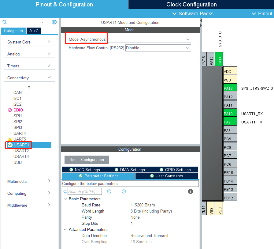
The mode of serial port 1 is modified to Asynchronous synchronous communication, baud rate is 115200, data width: 8 bits, check: None, stop bit: 1 bit.
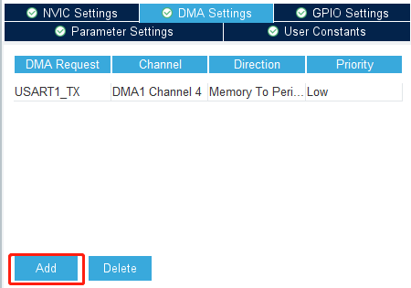
- Add a DMA send channel
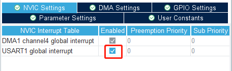
- Open the serial port 1 Interrupt Settings.
5.3. Analysis of experimental flow chart
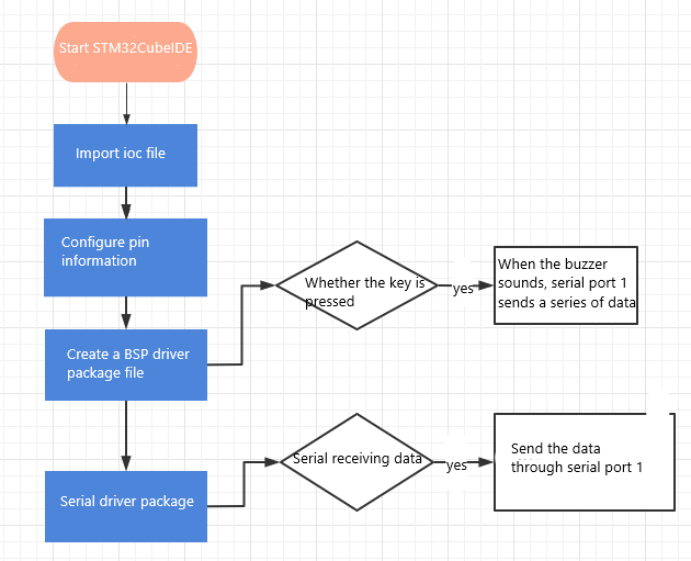
5.4. Core code interpretation
- Create the buzzer driver library bsp_uart.h and bsp_uart.c files in the BSP. Add the following to bsp_uart.h:

- Add the following content to bsp_uart.c:
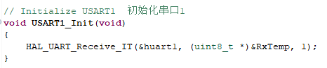
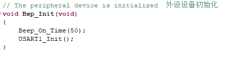
USART1_Init(): initializes content related to the serial port and enables the serial port to receive one data.
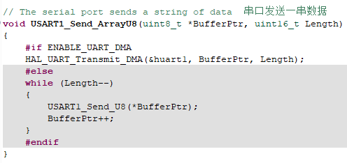
USART1_Send_U8(ch): serial port 1 sends one byte.

USART1_Send_ArrayU8(BufferPtr,Length): Serial port 1 sends a string of data. BufferPtr is the first address of the data, and Length is the length of the data.ENABLE_UART_DMA is a switch for serial 1 DMA.
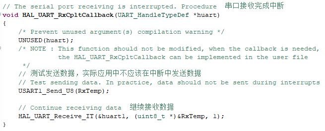
- Since the serial port 1 receive interrupt is performed only once, it needs to call receive data again after receiving data. In this case, to facilitate the test, the serial port is interrupted to send data. In actual applications, data should not be sent in the interrupt. Sending data through the serial port takes time, which may cause packet loss or even an error in the serial port.
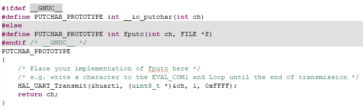
- Redefine printf to send data using serial port 1.
- In BSP initialization, call USART1_Init() and request to receive data.
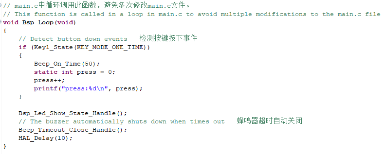
- After the key is pressed, add the printf() function to print information through serial port 1.
5.5. Hardware connection
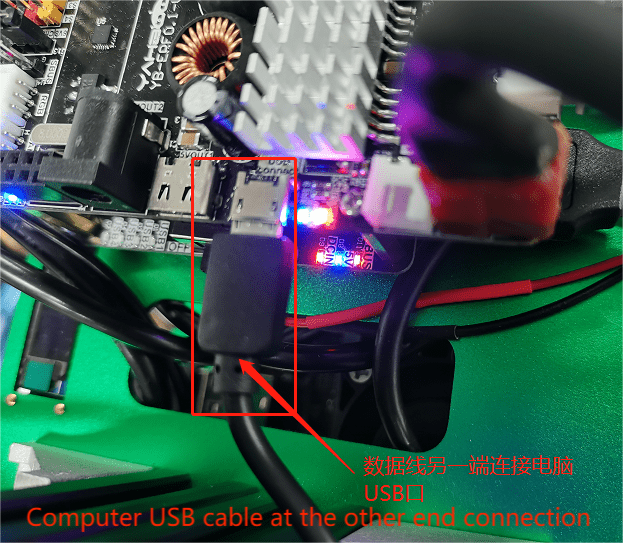
The expansion board needs to be connected to the USB port of the computer using a micro-USB cable. The connection diagram is as follows:
5.6. Experimental effect
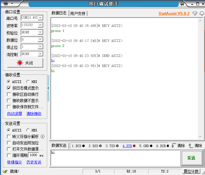
After the program is burned, the LED light flashes every 200 milliseconds, connect the expansion board to the computer through the micro-USB data cable, and open the serial assistant (specific parameters are shown in the figure below). Every time you press the button, the buzzer will ring for 50 milliseconds, you can see that the serial assistant will display press:xx, and every time you press the button xx will automatically add 1. The serial assistant sends character a, and the expansion board automatically returns character a. Since the above is used to send data in an interrupt, you cannot send too many characters at once, otherwise you will lose characters or even serial port errors.