yahboom
HomeLearn
Solution
Blog
Online Store
About Us
EN/中文
ROSMASTER R2📖
1.Preparation and First Trial
  • 1.1 Accessories introduction
  • 1.2 Precautions for battery
  • 1.3 First Trial
2.Assembly steps
  • Installaction Video
3.ROS1-Remote control course
  • 3.1 APP remote control
  • 3.2 Model aircraft remote control
  • 3.3 Handle remote control
4.ROS1-Hardware course
  • 4.1 About expansion board_V3.0
  • 4.1 About expansion board_V1.0
  • 4.2 STM32 Development environment
  • 4.3 Button to control the buzzer to whistle
  • 4.4 FreeRTOS application
  • 4.5 Serial communication
  • 4.6 SBUS model aircraft remote control
  • 4.7 CAN bus communication
  • 4.8 RGB colorful light bar
  • 4.9 Timer interrupt to control PWM servo
  • 4.10 Control serial port servos
  • 4.11 Nine-axis attitude sensor to obtain data
  • 4.12 Control motor
  • 4.13 Timer captures the encoder data
  • 4.14.1 Kinematic Analysis of Mecanum Wheel
  • 4.14.2 Kinematics Analysis of Ackermann Car
  • 4.15 PID control robot movement
5.ROS1-Basic course
  • 5.1 Update the firmware
  • 5.2 Turn off the self-starting process at startup
  • 5.3 Install the Rosmaster driver library
  • 5.4 Buzzer whistle
  • 5.5 Control PWM servo
  • 5.6 RGB colorful light bar special effects display
  • 5.7 Control motor
  • 5.8 Control robot movement
  • 5.9 Control Serial Servo
6.ROS1-Linux operating system
  • 6.1 Virtual machine installation and use
  • 6.2 Linux basics
  • 6.3 Remote control
  • 6.4 Multi-machine communication configuration
  • 6.5 Static IP and hotspot mode
  • 6.6 Bind the device ID
  • 6.7 Web page real-time monitoring
  • 6.8 Expansion tutorial
  • 6.9.1 Jetson Nano write sytem
  • 6.9.2 Jetson Xavier NX write system
  • 6.9.3 Jetson TX2 NX write system
  • 6.9.4 Raspberry Pi write system
7.ROS1-Docker-pi5
  • 1、Docker overview and docker installation
  • 2、Common commands for docker image containers
  • 3、Docker images deeply understand and publish images
  • 4、Docker hardware interaction and data processing
  • 5、Enter the bot's docker container
  • 6、Robot development environment construction in Docker
  • 7、How customers can update docker images in the future
8.ROS1-ROS basic course
  • 1.ROS introduction
  • 2.ROS installation
  • 3.ROS common command tools
  • 4.ROS workspace
  • 5.ROS function package
  • 6.ROS node
  • 7.ROS topic publisher
  • 8.ROS topic subscribers
  • 9.ROS service client
  • 10.ROS service server
  • 11.ROS action client
  • 12.ROS action server
  • 13.ROS custom message reception
  • 14.ROS-launch file
  • 15.ROS-TF transformation
  • 16.ROS parameter service
  • 17.ROS-rviz use
  • 18.ROS-rqt tool usage
  • 19.Topic message recording and playback
  • 20.urdf model introduction
  • 21.gazebo introduction
  • 22.ROS distributed communication
9.ROS1-OpenCV courses
  • 9.1 Getting started with Open Source CV
  • 9.2 Geometric transformation
  • 9.3 Image processing and drawing text line segments
  • 9.4 Image beautification
  • 9.5 Opencv application
  • 9.6 AR vision
  • 9.7 AR QR code
  • 9.8 ROS+Opencv foundation
  • 9.9 ROS+Opencv application
  • 9.10 Data transformation and point cloud
  • 9.11 MediaPipe development
10.ROS1-Robot control course
  • 10.1 PID algorithm theory
  • 10.2 Robot PID debugging
  • 10.3 Robot information release
  • 10.4 Robot keyboard control
  • 10.5 Robot handle control
  • 10.6 Robot state estimation
  • 10.7 Robot calibration
  • 10.8 Robot URDF model
11.ROS1-Depth camera course
  • 11.1 How to use the Astra camera
  • 11.2 Astra camera calibration
  • 11.3 Astra Color Tracking
  • 11.4 Astra Object Tracking
  • 11.5 Visual tracking autopilot
  • 11.6 Pure visual 2D mapping and navigation
  • 11.7 RTAB-Map 3D mapping navigation
  • 11.8 ORB_SLAM2 basics
  • 11.9 ORB_SLAM2_Octomap
12.ROS1-Lidar course
  • 11.1 Lidar basic-SLAM
  • 11.1 Lidar basic-EAI
  • 11.2 Lidar avoiding
  • 11.3 Lidar guard
  • 11.4 Lidar follow
  • 11.5 Patrol game
  • 11.6 gmapping mapping
  • 11.7 hector mapping
  • 11.8 karto mapping
  • 11.9 cartographer mapping
  • 11.10 rrt_exploration mappin
  • 11.11 AMCL
  • 11.12 Navigation and avoiding
  • 11.13 APP mapping and navigation
  • 11.14 TEB path planning algorithm
13.ROS1-Multi-robot control course
  • 13.1 Multi-machine handle control
  • 13.2 Multi-machine navigation
  • 13.3 Multi-machine formation
  • 13.4 Multi-machine surround
14.ROS1-Deep learning courses
  • 14.1 KNN recognizes handwritten digits
  • 14.2 Basic use of TensorFlow
  • 14.3 Basic use of PyTorch(jetson)
  • 14.4 yolov5 model training(jetson)
  • 14.5 yolov5+tensorrt acceleration(jetson)
  • 14.6 yolov4-tiny
15.ROS1-Voice control courses
  • 15.0 How to use old voice module in new image
  • 15.1 Introduction of voice control module-NEW
  • 15.2 Voice control module port binding-NEW
  • 15.1 Introduction of voice control module-Old
  • 15.2 Voice control module port binding-Old
  • 15.3 Voice control car movement
  • 15.4 Voice control Autopilot
  • 14.5 Voice control color recognition
  • 15.6 Voice control color tracking
  • 15.7 Voice control multi-point navigation
16.ROS1-Model training Autopilot
  • 16.0 ReadMe
  • 16.1 yolov5 to train traffic signs
  • 16.2 TensorRt acceleration identification mark
  • 16.3 Road sign indication function description
  • 16.4 Collect data
  • 16.5 Training model
  • 16.6 Model transformation and application
  • 16.7 AI Autopilot
17. ROS2-Remote control course
  • 1. APP remote control
  • 2. Model aircraft remote control
  • 3. Handle remote control
18.ROS2-Hardware course
  • 1. Expansion board introduction_V3.0
  • 1. Expansion board introduction_V1.0
  • 2. STM32 development environment build
  • 3. Key control buzzer sounding
  • 4. FreeRTOS applications
  • 5. Serial communication
  • 6. SBUS model airplane remote control
  • 7. CAN bus communication
  • 8. RGB colorful light bar
  • 9. Timer interrupt control PWM servos
  • 10. Control serial servos
  • 11. Nine-axis attitude sensor acquires data
  • 12. Control motor forward and reverse
  • 13. Timer Capture Encoder Data
  • 14. Theory of Robot Kinematics Analysis
  • 14.1.Mecanum wheel
  • 14.2.Ackerman
  • 14.3.4WD
  • 15. PID control of robot motion
19. ROS2-Basic course
  • 1. Update the firmware of the expansion board
  • 2.Close the large self-starting program at boot
  • 3. Install Rosmaster driver library
  • 4. Buzzer sounding
  • 5. Control PWM servo
  • 6. RGB colorful light bar special effects show
  • 7. Control motor forward and reverse
  • 8. Controlling robot motion
  • 9. Control serial servos
20. ROS2-Linux operating systemnew
  • 01. Virtual Machines
  • 02. Linux Basics
  • 03. Remote control
  • 04. Multi-computer communication configuration
  • 05. Static ip and hotspot mode
  • 06. Bind device ID
  • 07.Webpage real-time monitoring
  • 08. Expansion Tutorial
  • 09-1.Jetson Nano write system file
  • 09-2. Raspberry Pi write system file
  • 09-3.Orin write system
  • 10.Jetpack old system upgraded to SUPER systemnew
21.ROS2 -Docker(Nano Pi)
  • 1. docker overview and docker installation
  • 2. docker image container common command
  • 3. docker image in-depth understanding and publishing images
  • 4. docker hardware interaction and data processing
  • 5. Enter the docker container of the robot
  • 6. docker in the robot development environment build
  • 7. Customer's method of updating docker images in the future
22.ROS2- ROS2 Basic Tutorial
  • 1.Introduction to ROS2
  • 2.ROS2 install Humble
  • 3.ROS2 development environment
  • 4.ROS2 workspace
  • 5.ROS2 function package
  • 6.ROS2 node
  • 7.ROS2 topic communication
  • 8.ROS2 service communication
  • 9.ROS2 action communication
  • 10.ROS2 custom interface message
  • 11.ROS2 parameter service case
  • 12.ROS2 meta-function package
  • 13.ROS2 distributed communication
  • 14.ROS2 DDS
  • 15.ROS2 time related API
  • 16.ROS2 common command tools
  • 17.ROS2 rviz2 use
  • 18.ROS2 Rqt Toolbox
  • 19.ROS2 Launch startup file configuration
  • 20.ROS2 recording and playback tool
  • 21.ROS2 URDF model
  • 22.ROS2 Gazebo simulation platform
  • 23.ROS2 TF2 coordinate transformation
23. ROS2-Robot control course
  • 1. PID algorithm theory
  • 2. Robot information release
  • 3. Robot control
  • 4. Robot state estimation
  • 5. Robot calibration
  • 6. URDF model
24. ROS2-Lidar course
  • 1-1. Introduction and use of SLAM lidar
  • 1-2. Introduction and use of 4ROS lidar
  • 2. Lidar obstacle avoidance fun gameplay
  • 3. Lidar tracking fun gameplay
  • 4. Patrol function play
  • 5. gmapping map building algorithm
  • 6. cartographer building algorithm
  • 7. Navigation and obstacle avoidance
  • 8. Rosmaster_R2 using the app to build maps
  • 9. Rosmaster_R2 navigating with the app
25. ROS2-OpenCV courses
  • 1. opencv basic course
  • 2. ROS+opencv application
  • 3. QR code creation and recognition
  • 4. AR Vision
  • 5. mediapipe fun gameplay
  • 6. Patrol line autopilot
26. ROS2-Depth camera courses
  • 1. Depth camera use
  • 2. Camera calibration
  • 3. Color tracking
  • 4. KCF object tracking
  • 5. ORB_SLAM2 Basics
  • 6. ORB_SLAM2 PCL mapping
  • 7. ORB_SLAM2 Octomap mapping
  • 8. RTAB-Map 3D mapping navigation
27.ROS2- Voice control courses
  • 0. How to use old voice module in new image
  • 1.1 Introduction to the module-New
  • 1.2 Voice Control Module Port Binding-New
  • 1.3 Introduction to the module-Old
  • 2. Voice control car movement
  • 3. Voice control autopilot
  • 4. Voice control color recognition
  • 5. Voice control color tracking
  • 6. Voice control multi-point navigation
28.Deep learning courses(SUPER)
  • 1.KNN recognizes handwritten digitsnew
  • 2.Basic use of TensorFlownew
  • 3.Basic use of PyTorch(jetson)new
  • 4.YOLOv11Model conversion(SUPER)new
  • 5.YOLOv11Dataset annotation(SUPER)new
  • 6.YOLOv11Model conversion + tensorrt acceleration(SUPER)new
  • 7.YOLOv11Object recognition(SUPER)new
29. ROS2-Multi-robot control
  • 1. Multi-robot control
  • 2. Multi-robot navigation
LLM tutorial
1.Development environment
  • 0. Model usage instructions
  • 1.Environments deployment
  • 2.Dialogue platform installation
2.Jetson Nano B01
  • 1.Qwen2 model
  • 2.TinyLlama model
  • 3.Phi-3 model
  • 4.Gemma model
  • 5.Orca Mini model
  • 6.StarCoder2 model
  • 7.DeepSeek-R1 model
  • 8.Expand LLaVA-Phi3
3.Jetson Orin NXNANO
  • 1.Llama3 model
  • 2.Qwen2 model
  • 3.Phi-3 model
  • 4.Gemma model
  • 5.WizardLM2 model
  • 6.Codellama model
  • 7.DeepSeek-R1 model
  • 8.Orca Mini model
  • 9.StarCoder2 model
  • 10.TinyLlama model
  • 11.Expand LLaVA
  • 12.Expand LLaVA-Phi3
4.Raspberry Pi 5B
  • 1.Meta AI Llama3 model
  • 2.Qwen2 model
  • 3.Phi-3 model
  • 4.Gemma model
  • 5.WizardLM2 model
  • 6.Meta AI Codellama model
  • 7.DeepSeek-R1 model
  • 8.Expand LLaVA
FAQ
  • 1.Using your own Jetson board, car cannot start normally
Download
  • RemoteCtrl_APP(iOS/Android)
  • Mapping_APP(iOS_Android)
  • Instruction Manual
  • SystemFile_ROS1
  • SystemFile_ROS2
  • SystemFile_ROS2_OrinNANOSUPER
  • SystemFile_ROS2_OrinNXSUPER
  • VM software
  • Code
  • Jetson_Boot_USB.tar.gz
  • Autopilot Annex
  • Other_Annex_File
  • LLM_SystemFile
  • ROS2_Basic_VM
Download ZIP

Welcome to ROSMASTER R2 repository

4.5 Serial communication

5. Serial communication

5. Serial communication 5.1. Purpose of the experiment 5.2. Configuration pin information 5.3. Analysis of the experimental flow chart 5.4. core code explanation 5.5. Hardware connection 5.6. Experimental effect

5.1. Purpose of the experiment

Use the serial port communication of STM32, receive the data of the serial port assistant, and return the received data to the serial port, redefine the printf function.

5.2. Configuration pin information

Since each new project needs configuration information, it is more troublesome. Fortunately, STM32CubeIDE provides the function of importing .ioc files, which can help us save time.

1.Import the ioc file from the BEEP project and name it Serial.

Change the mode of serial port 1 to Asynchronous synchronous communication, the baud rate is 115200, the data width: 8 bits, the test: None, and the stop bit: 1 bit.
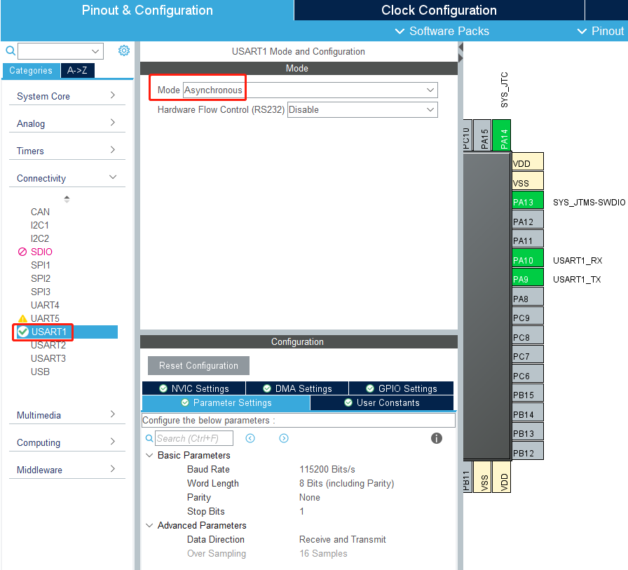
image-20220309173020409

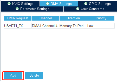
2.Add DMA sending channel

image-20220309174341557

  1. Open serial port 1 interrupt settings.
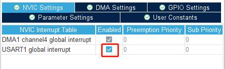
image-20220309174427994

5.3. Analysis of the experimental flow chart
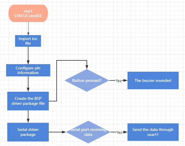
image-20220519095253727

5.4. core code explanation

  1. Create new buzzer driver library bsp_uart.h and bsp_uart.c files in BSP. Add the following to bsp_uart.h:

image-20220309181653775

  1. Add the following in bsp_uart.c:

USART1_Init(): Initialize the related content of the serial port, open the serial port to receive 1 data.
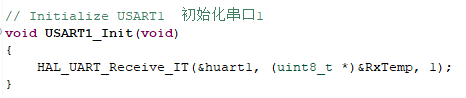
image-20220309183608315

USART1_Send_U8(ch): Serial port 1 sends a byte.

image-20220309183632327

USART1_Send_ArrayU8(BufferPtr,Length): Serial port 1 sends a string of data, BufferPtr is the first address of the data, and Length is the length of the data. ENABLE_UART_DMA is the switch of serial port 1 DMA.
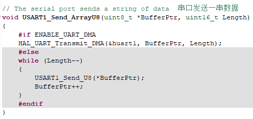
image-20220309183656718

  1. Since the serial port 1 receive interrupt is only performed once, it is necessary to call the receive data again after receiving the data. In order to facilitate the test, the serial port is called in an interrupt to send data. In practical applications, data should not be sent in an interrupt. It is time-consuming to send data through the serial port, which may cause problems such as packet loss or even serial port errors.
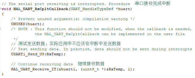
image-20220309183851258

  1. Redefine printf to use serial port 1 to send data.
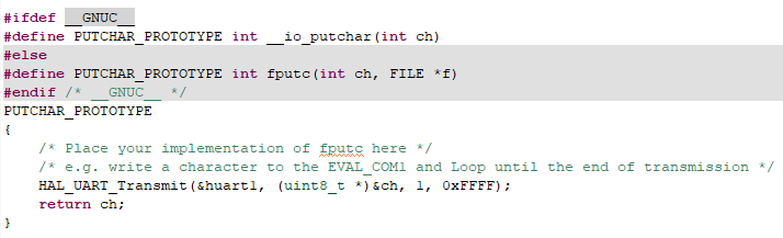
image-20220309184205569

  1. In BSP initialization, call USART1_Init() function to request to receive data.
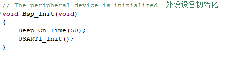
image-20220310092311388

  1. After the button is pressed, add the printf() function to print information through serial port 1.
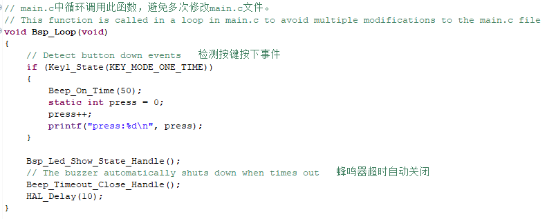
image-20220310092529061

5.5. Hardware connection

The expansion board needs to be connected to the USB port of the computer using a micro-USB data cable. The connection diagram is as follows:
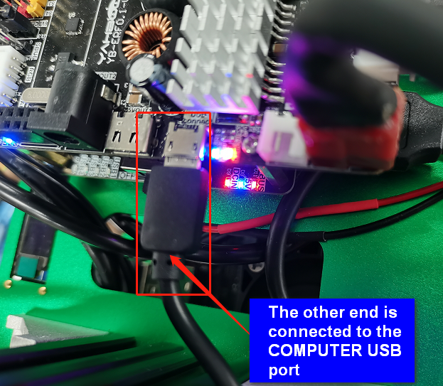
image-20220519095456695

5.6. Experimental effect

After programming the program, the LED light flashes once every 200 milliseconds. Connect the expansion board to the computer through the micro-USB data cable and open the serial port assistant (the specific parameters are shown in the figure below). The buzzer will sound every time the button is pressed. After 50 milliseconds, you can see that the serial port assistant will display press:xx, and each time you press the button xx will automatically increase by 1. The serial port assistant sends the character a, and the expansion board will automatically return the character a. Since the above uses to send data in an interrupt, you cannot send too many characters at a time, otherwise characters will be lost or even serial port errors will occur.
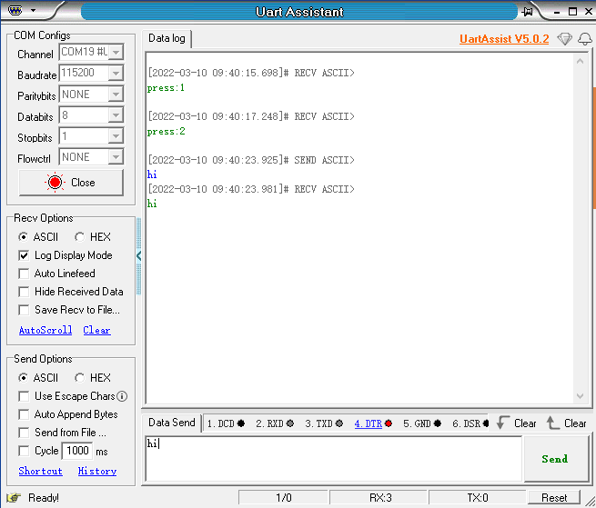
image-20220519095723451

FreeRTOS application
SBUS model aircraft remote control

COMPANY

  • About us
  • Team Style
  • Blog

LEARNING & EXPLORATION

  • Tutorials
  • Edge AI hardware
  • Educational robots
  • Embedded intelligent hardware

WHERE TO BUY

  • Yahboom Online Store
  • Amazon
  • Alibaba
  • AliExpress
  • Mercado

TECHNOLOGY SUPPORT

  • Email: support@yahboom.com

BE A DISTRIBUTOR

  • Email: sales@yahboom.com
QR Code
QR Code

Copyright © 2017-2026 Yahboom. All Rights Reserved.

EN/中文