Welcome to ROSMASTER R2 repository
11.10 rrt_exploration mappin
10. rrt_exploration mapping algorithm
10. rrt_exploration mapping algorithm10.1. Introduction10.2. Use10.2.1. Start10.2.2. Mapping10.2.3. Map saving10.2.4. Node View10.2.5. View tf tree10.3, global_rrt_frontier_detector10.3.1. Introduction10.3.2, Topics and Services10.3.3. Configuration parameters10.4, local_rrt_frontier_detector10.4.1. Introduction10.4.2, Topics and Services10.4.3. Configuration parameters10.5, frontier_opencv_detector10.5.1. Introduction10.5.2, Topics and Services10.5.3. Configuration parameters10.6, filter10.6.1. Introduction10.6.2, Topics and Services10.6.3. Configuration parameters10.7、Assigner10.7.1. Introduction10.7.2, Topics and Services10.7.3. Configuration parameters
rrt_exploration: http://wiki.ros.org/rrt_exploration
rrt_exploration/Tutorials: http://wiki.ros.org/rrt_exploration/Tutorials
map_server: https://wiki.ros.org/map_server
10.1. Introduction
RRT exploration is a search algorithm implemented based on the RRT path planning algorithm. The reason why the RRT algorithm is used is that RRT has a strong tendency for unknown areas. In RRT exploration, RRT is mainly used to generate boundary points, which is very beneficial for exploring boundary points. The so-called boundary point is the intersection point between the explored and unknown areas. Here is a definition: for all areas, if they have been explored, the area without obstacles is recorded as 0, and the area with obstacles is recorded as 1. , the unknown area is recorded as -1, and at the beginning, the entire area is recorded as -1.
The framework of the Rapid Exploration Random Tree (RRT) algorithm is as follows:
Global RRT frontier point detector node.
Local RRT frontier point detector node.
OpenCV-based frontier detector node.
Filter node.
Assigner node.
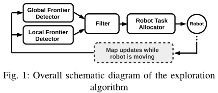
There are 3 types of nodes: nodes for detecting boundary points in the occupied raster map, nodes for filtering detected points, and nodes for assigning points to robots.
10.2. Use
Note: When building a map, the slower the speed, the better the effect (note that the rotation speed should be slower). If the speed is too fast, the effect will be poor.
According to different models, you only need to set the purchased model in [.bashrc], X1 (normal four-wheel drive) X3 (Mailun) Take X3 as an example
#Raspberry Pi 5 master needs to enter docker first, please perform this step#If running the script into docker fails, please refer to ROS/07, Docker tutorial~/run_docker.shOpen the [.bashrc] file
xxxxxxxxxxsudo vim .bashrc
Find the [ROBOT_TYPE] parameters and modify the corresponding car model
xxxxxxxxxxexport ROBOT_TYPE=X3 # ROBOT_TYPE: X1 X3 X3plus R2 X710.2.1. Start
Start the command (robot side). For the convenience of operation, this section takes [mono + laser + yahboomcar] as an example.
xxxxxxxxxxroslaunch yahboomcar_nav laser_bringup.launch # laser + yahboomcarroslaunch yahboomcar_nav laser_usb_bringup.launch # mono + laser + yahboomcarroslaunch yahboomcar_nav laser_astrapro_bringup.launch # Astra + laser + yahboomcarMapping command (robot side)
<PI5 needs to open another terminal to enter the same docker container
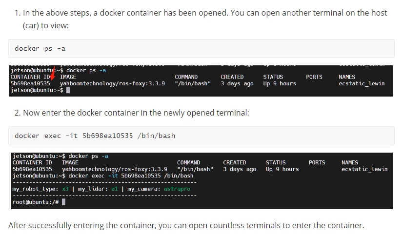
xxxxxxxxxxroslaunch yahboomcar_nav rrt_exploration.launch use_rviz:=false[use_rviz] parameter: whether to enable rviz visualization.
Turn on the visual interface (virtual machine side)
xxxxxxxxxxroslaunch yahboomcar_nav view_rrt_map.launch
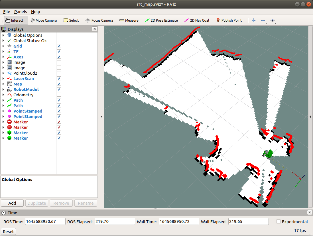
The gap at the back of the robot is due to the obstruction caused by the installation position of the display screen, so a certain range of radar data is blocked. The shielding range can be adjusted, or it can not be blocked according to the actual situation. For specific operations, see [01. Radar Basic Course].
10.2.2. Mapping
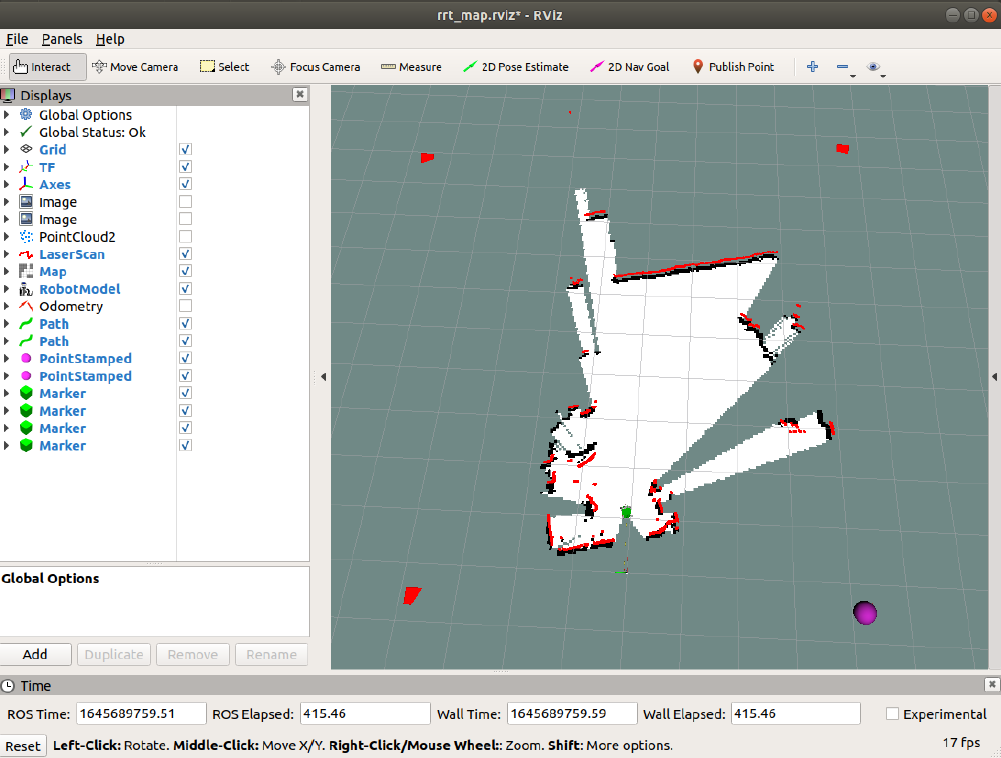
Click [Publish Point] on the [rviz] interface, and then click on the map. Every time before clicking a point on the map, you must first select [Publish Point]. Click four points clockwise or counterclockwise. The last point is near the car. After selecting five points as required, the robot begins to explore and build the map.
10.2.3. Map saving
After the map construction is completed, the map will be automatically saved and returned to zero point. The map is saved to the ~/yahboomcar_ws/src/yahboomcar_nav/maps folder, the name is rrt_map, and can be modified in the [simple.launch] file.
rrt_map.yaml
xxxxxxxxxximage: map.pgmresolution: 0.05origin: [-15.4,-12.2,0.0]Negate: 0occupied_thresh: 0.65free_thresh: 0.196Parameter analysis:
image: The path of the map file, which can be an absolute path or a relative path.
resolution: resolution of the map, meters/pixel
Origin: 2D pose (x, y, yaw) in the lower left corner of the map. The yaw here is rotated counterclockwise (yaw=0 means no rotation). Many parts of the current system ignore the yaw value.
negate: whether to reverse the meaning of white/black and free/occupied (the interpretation of the threshold is not affected)
occupied_thresh: Pixels with an occupation probability greater than this threshold will be considered fully occupied.
free_thresh: Pixels with occupancy probability less than this threshold will be considered completely free.
10.2.4. Node View
xxxxxxxxxxrqt_graph
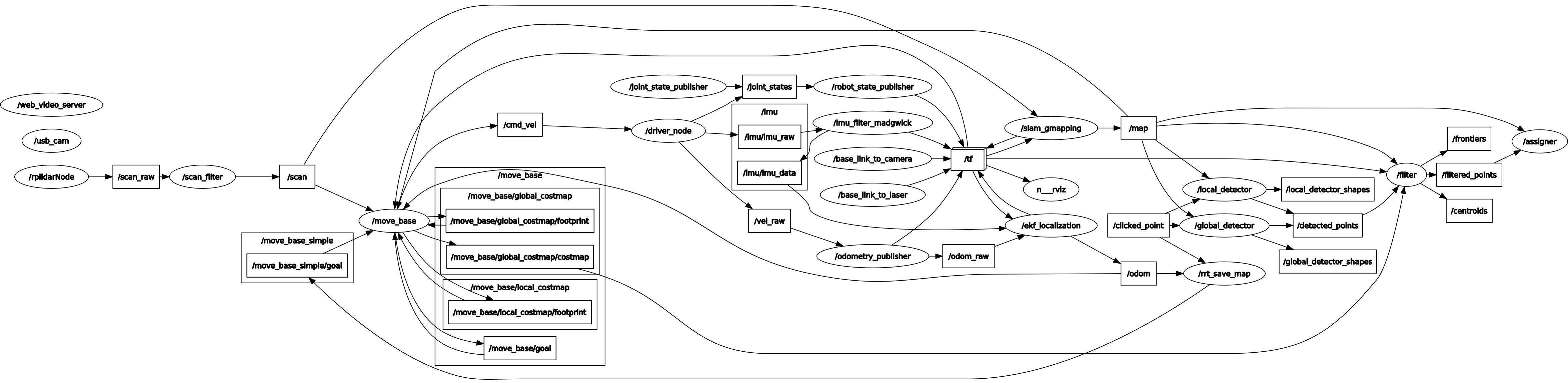
10.2.5. View tf tree
xxxxxxxxxxrosrun rqt_tf_tree rqt_tf_tree
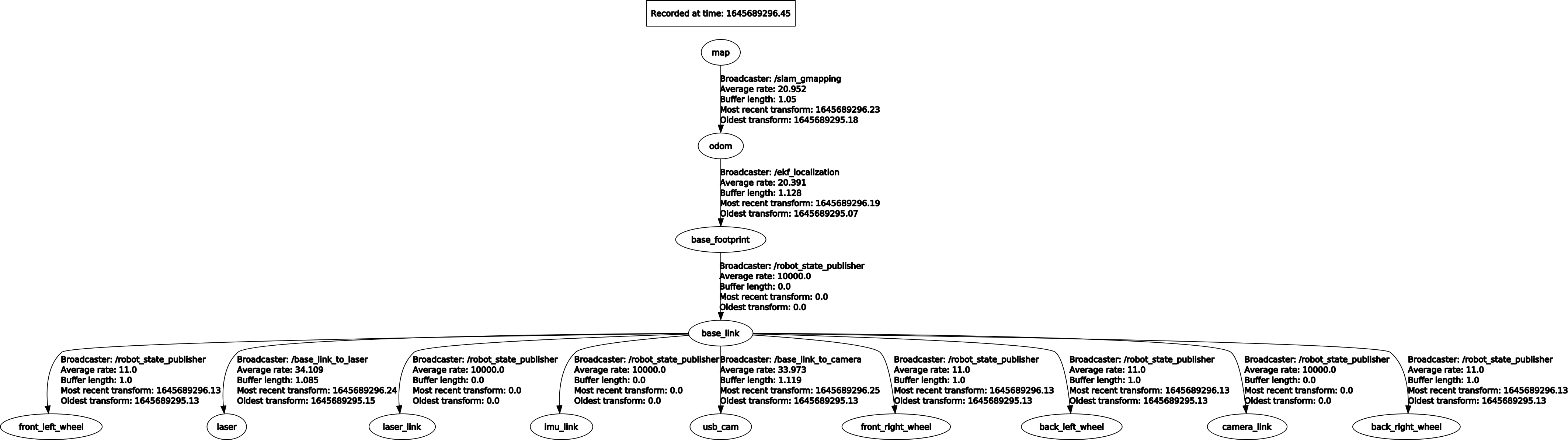
10.3, global_rrt_frontier_detector
10.3.1. Introduction
The global_rrt_frontier_detector node takes the occupancy grid and finds boundary points (i.e. exploration targets) in it. It publishes detected points so that filter nodes can process them. In a multi-bot configuration, only one instance of this node is run. If needed, running additional instances of the global boundary detector can increase the speed of boundary point detection.
10.3.2, Topics and Services
| Subscription topic | Type | Description |
|---|---|---|
| map | nav_msgs/OccupancyGrid | The topic name is defined by the ~map_Topic parameter. It is the topic name that this node receives. |
| clicked_point | geometry_msgs/PointStamped | global_rrt_frontier_detector The area to be detected by the node. This topic is where nodes receive five points that define an area. The first four points are the four points that define the square area to be explored, and the last point is the starting point of the tree. After announcing these five points, RRT will start detecting border points. |
| Post Topic | Type | Description |
| detected_points | geometry_msgs/PointStamped | Topic for publishing detected boundary points. |
| shapes | visualization_msgs/Marker | Publish RRT imaginary line shapes for viewing with Rviz. |
10.3.3. Configuration parameters
| Parameters | Type | Default value | Description |
|---|---|---|---|
| ~map_topic | string | "/robot_1/map" | This node receives the map topic mapping name |
| ~eta | float | 5.0 | This parameter controls the growth rate of the RRT used to detect boundary points, in meters. This parameter should be set according to the map size, very large values will cause the tree to grow faster and thus detect boundary points faster, but a large growth rate will also mean that the tree will lose small corner points in the map |
10.4, local_rrt_frontier_detector
10.4.1. Introduction
This node is similar to global_rrt_frontier_detector. However, it works differently because the tree here is constantly reset every time a boundary point is detected. This node will run along the global boundary detector node, which is responsible for quickly detecting boundary points located near the robot.
In a multi-robot configuration, each robot runs a local detector instance. So, for a team of 3 robots, there will be 4 nodes for detecting boundary points; 3 local detectors and 1 global detector. If needed, running additional instances of the local boundary detector can increase the speed of boundary point detection. All detectors will publish detected boundary points ("/detected_points") on the same topic.
10.4.2, Topics and Services
| Subscription topic | Type | Description |
|---|---|---|
| map | nav_msgs/OccupancyGrid | The name of the map topic subscribed to by this node. |
| clicked_point | geometry_msgs/PointStamped | Similar to the global_rrt_frontier_detector node |
| Post Topic | Type | Description |
| detected_points | geometry_msgs/PointStamped | Release detectionto the topic of boundary points. |
| shapes | visualization_msgs/Marker | Publish RRT imaginary line shapes for viewing with Rviz. |
10.4.3. Configuration parameters
| Parameters | Type | Default value | Description |
|---|---|---|---|
| ~/robot_1/base_link | string | "/robot_1/base_link" | The frame to connect to the robot. Each time the RRT tree is reset, it will start from the current robot position obtained in this coordinate system. |
| ~map_topic | string | "/robot_1/map" | This node receives the map topic mapping name |
| ~eta | float | 5.0 | This parameter controls the growth rate of the RRT used to detect boundary points, in meters. This parameter should be set according to the map size, very large values will cause the tree to grow faster and thus detect boundary points faster, but a large growth rate will also mean that the tree will lose small corner points in the map |
10.5, frontier_opencv_detector
10.5.1. Introduction
This node is another boundary detector, but it is not based on RRT. This node uses OpenCV tools to detect boundary points. It is designed to run standalone, and in a multi-bot configuration, only one instance should be run (running additional instances of this node will not make any difference).
Initially, this node was implemented for comparison with RRT-based boundary detectors. Running this node along RRT detectors (local and global) improves the speed of boundary point detection.
Note: You can run any type and number of detectors, all detectors will be published on the same topic to which the filter node (explained in the next section) is subscribed. The filter, on the other hand, passes the filtered boundary points to the allocator in order to command the robot to explore these points.
10.5.2, Topics and Services
| Subscription topic | Type | Description |
|---|---|---|
| map | nav_msgs/OccupancyGrid | The name of the map topic subscribed to by this node. |
| Post Topic | Type | Description |
| detected_points | geometry_msgs/PointStamped | Topic for publishing detected boundary points. |
| shapes | visualization_msgs/Marker | Publish RRT imaginary line shapes for viewing with Rviz. |
10.5.3. Configuration parameters
| Parameters | Type | Default value | Description |
|---|---|---|---|
| ~map_topic | string | "/robot_1/map" | This node receives the map topic mapping name |
10.6, filter
10.6.1. Introduction
This Node node receives detected boundary points from all detectors, filters these points, and passes them to the distribution node to command the robot. Filtering includes deleting old and invalid points, as well as deleting redundant points.
10.6.2, Topics and Services
| Subscription topic | Type | Description |
| -------------------------------------------------- -- | -------------------------- | -------------------- ---------------------------------------- |
| map | nav_msgs/OccupancyGrid | The topic name is defined by the ~map_Topic parameter. It is the topic name that this node receives. |
| robot_x/move_base_node
/global_costmap/costmap | nav_msgs/OccupancyGrid | x is the number of the robot. This node subscribes to the topic of all costmaps for all robots and therefore requires a costmap. Normally, the cost map should be published by navigation (after turning navigation on the robot, each robot will have a cost map). For example, if n_robots=2, the nodes will subscribe to: robot_1/move_base_node/global_costmap/costmap and robot_2/move_base_node/global_costmap/costmap. The cost map is used to remove invalid points.
Note: The namespace of all nodes corresponding to robots should start with robot_x. |
| detected_points | geometry_msgs/PointStamped | Topic name defined by ~goals_topic. It is the topic where the filter node receives the boundary detection point. |
| Post Topic | Type | Description |
| frontiers | visualization_msgs/Marker | The filter node publishes only the topics of filtered boundary points. |
| centroids | visualization_msgs/Marker | The filter node publishes the topic of the received boundary points. |
| filtered_points | MsgLink(msg/type) | All filtered points are sent to the assigner node of this topic as a point array. |
10.6.3. Configuration parameters
| Parameters | Type | Default value | Description |
|---|---|---|---|
| ~map_topic | string | "/robot_1/map" | This node receives the map topic mapping name |
| ~costmap_clearing_threshold | float | 70.0 | Costmap clearing threshold |
| ~info_radius | float | 1.0 | The information radius used to calculate the information gain of boundary points. |
| ~goals_topic | string | /detected_points | Defines the topic for nodes to receive detected boundary points |
| ~n_robots | float | 1.0 | Number of robots |
| ~namespace | string | namespace | |
| ~namespace_init_count | float | 1.0 | Namespace index |
| ~rate | float | 100.0 | Node cycle rate in Hz. |
10.7、Assigner
10.7.1. Introduction
This node receives target detection targets, i.e. filtered boundary points published by the filtering node, and commands the robot accordingly. The evaluator node commands the robot through move_base_node. This is why navigation is enabled on the robot.
10.7.2, Topics and Services
| Subscription topic | Type | Description |
|---|---|---|
| map | nav_msgs/OccupancyGrid | The topic name is defined by the ~map_Topic parameter. It is the topic name that this node receives. |
| frontiers_topic | nav_msgs/OccupancyGrid | The topic name is defined by the ~frontiers_topic parameter |
10.7.3. Configuration parameters
| Parameters | Type | Default value | Description |
|---|---|---|---|
| ~map_topic | string | "/robot_1/map" | This node receives the map topic mapping name |
| ~info_radius | float | 1.0 | The information radius used to calculate the information gain of boundary points. |
| ~info_multiplier | float | 3.0 | Units are meters. This parameter is used to emphasize the importance of the information gain of a boundary point relative to the cost (expected travel distance to the boundary point). |
| ~hysteresis_radius | float | 3.0 | Units are meters. This parameter defines the hysteresis radius. |
| ~hysteresis_gain | float | 2.0 | Units are meters. This parameter defines the hysteresis gain. |
| ~frontiers_topic | string | /filtered_points | This node receives the topic of the frontier points. |
| ~n_robots | float | 1.0 | Number of robots |
| ~namespace | string | namespace | |
| ~namespace_init_count | float | 1.0 | Starting indexing of robot names. |
| ~delay_after_assignement | float | 0.5 | The unit is seconds. It defines the amount of delay after each robot allocation. |
| ~global_frame | string | "/map" | For global coordinate system. In a single robot, it is the same as the "map_topic" parameter. In the case of multiple robots, the coordinate system name corresponds to the global coordinate system name. |