Welcome to ROSMASTER R2 repository
7. CAN bus communication
7. CAN bus communication
7. CAN bus communication7.1. Purpose of the experiment7.2 Configuring Pin Information7.3. Experimental flow chart analysis7.4. Core Code Explanation7.5. Hardware connection7.6 Experimental effect
7.1. Purpose of the experiment
Use the CAN communication of STM32, using loopback mode, key control to send CAN data, interrupt to receive CAN data and print it out through serial assistant.
7.2 Configuring Pin Information
As we need to configure the information every time we create a new project, it is quite troublesome, good thing STM32CubeIDE provides the function of importing .ioc file, which can help us save time.
- Import the ioc file from Serial's project and name it CAN.
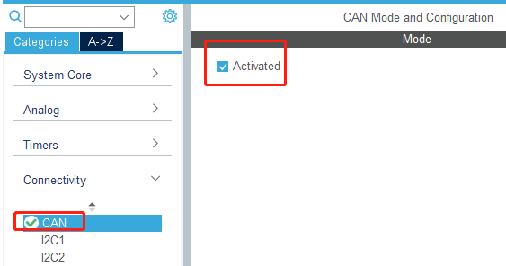
Find CAN in Connectivity and check Activated to enable CAN peripheral.
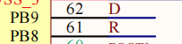
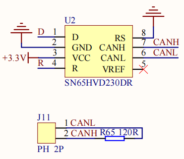
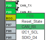
- According to the schematic diagram, it can be seen that the pins connected to the CAN bus are PB8 and PB9, while the default CAN bus pins are PA11 and PA12, so you need to manually modify the CAN bus pins to PB8 and PB9.
- Set the parameters of the CAN peripheral, here we set the baud rate to 1000kbps and the mode to Loopback.
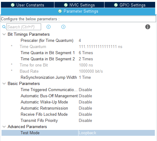
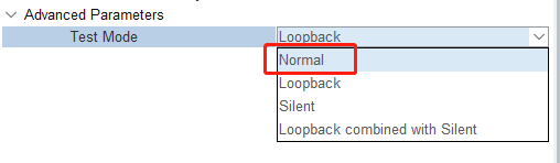
Since it is only used to test the communication here, Loopback mode (self-sending and self-collecting data) is selected; if you need to connect a third-party CAN device, please select the Normal mode (data receiving/transmitting independently).
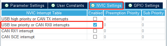
- Turn on the CAN RX0 interrupt in the interrupt setting. If the interrupt is not turned on, the data cannot be received.
7.3. Experimental flow chart analysis
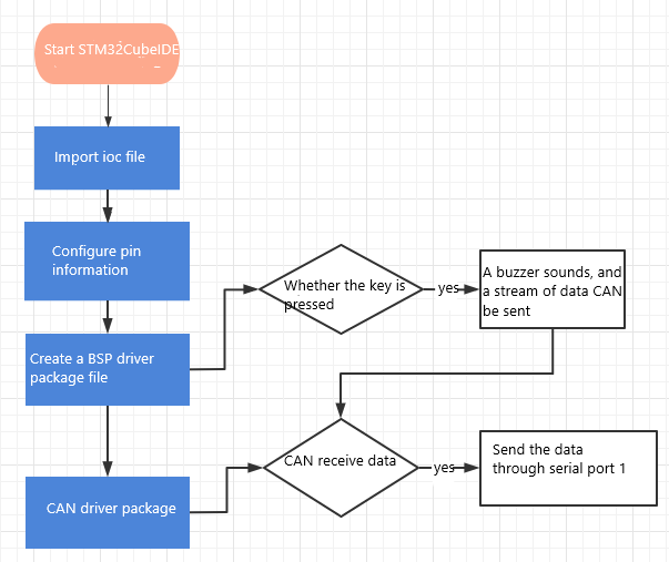
7.4. Core Code Explanation
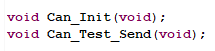
- Create a new buzzer driver library bsp_can.h and bsp_can.c file in BSP. Add the following to bsp_can.h:
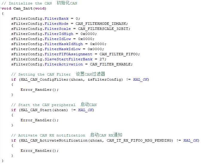
- Add the following contents in bsp_can.c:
Can_Init():Initialize CAN peripheral related contents, set CAN receive filter, and open CAN bus communication.
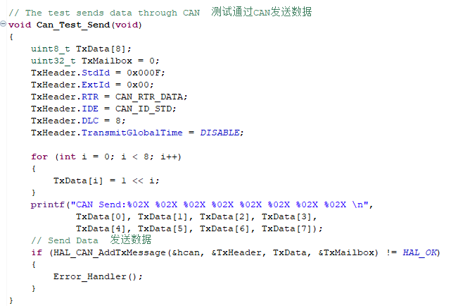
- In order to test the sent data, create a new Can_Test_Send() function to send the data out via CAN and print it to the serial port assistant. If you need to modify the sent data, just modify the TxData array before sending.
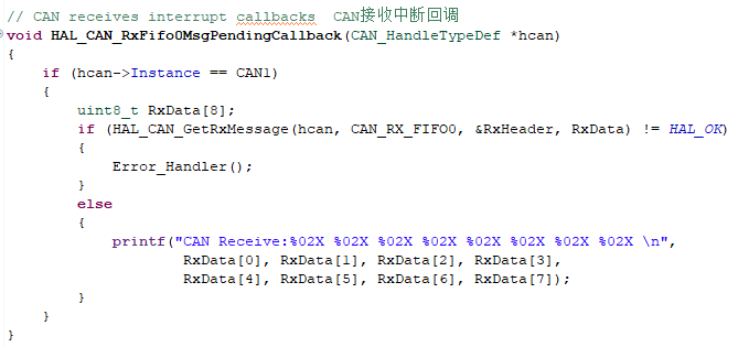
- CAN receive interrupt callback function, will receive CAN data through the serial port print out. The name of this function can not be changed, otherwise this function can not be called.
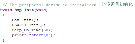
- In BSP initialization, call the Can_Init() function to initialize the CAN peripheral.
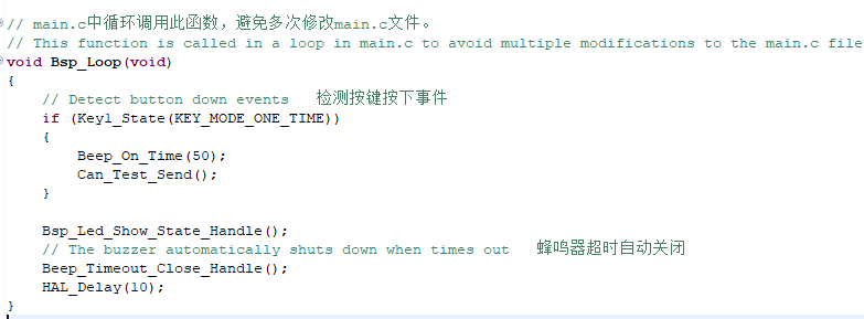
- Add the function of sending CAN data after a key is pressed.
7.5. Hardware connection
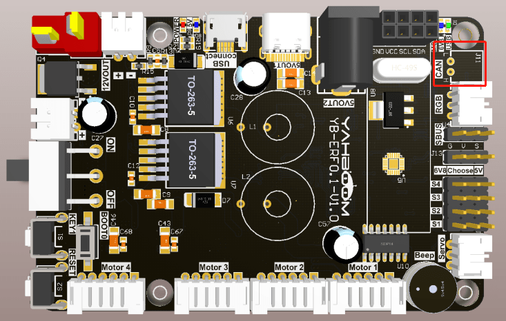
Since the loopback mode is used, the CAN interface can be used without connecting an external device.
7.6 Experimental effect
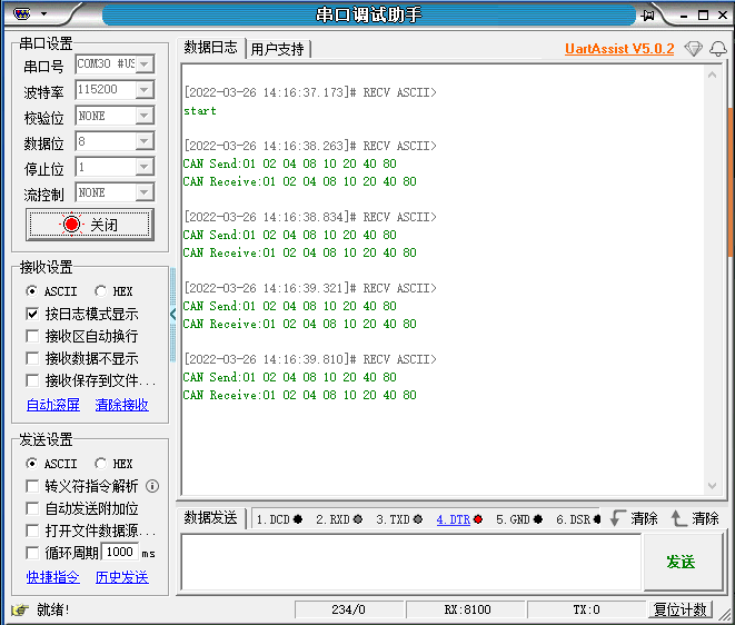
After burning the program, the LED flashes every 200 milliseconds, connect the expansion board to the computer through the micro-USB cable and open the serial port assistant (the specific parameters are shown in the following figure), every time you press the key, the buzzer will sound for 50 milliseconds, and you can see that the serial port assistant displays the data sent by the CAN as well as the data received by the CAN.