yahboom
HomeLearn
Solution
Blog
Online Store
About Us
EN/中文
ROSMASTER R2📖
1.Preparation and First Trial
  • 1.1 Accessories introduction
  • 1.2 Precautions for battery
  • 1.3 First Trial
2.Assembly steps
  • Installaction Video
3.ROS1-Remote control course
  • 3.1 APP remote control
  • 3.2 Model aircraft remote control
  • 3.3 Handle remote control
4.ROS1-Hardware course
  • 4.1 About expansion board_V3.0
  • 4.1 About expansion board_V1.0
  • 4.2 STM32 Development environment
  • 4.3 Button to control the buzzer to whistle
  • 4.4 FreeRTOS application
  • 4.5 Serial communication
  • 4.6 SBUS model aircraft remote control
  • 4.7 CAN bus communication
  • 4.8 RGB colorful light bar
  • 4.9 Timer interrupt to control PWM servo
  • 4.10 Control serial port servos
  • 4.11 Nine-axis attitude sensor to obtain data
  • 4.12 Control motor
  • 4.13 Timer captures the encoder data
  • 4.14.1 Kinematic Analysis of Mecanum Wheel
  • 4.14.2 Kinematics Analysis of Ackermann Car
  • 4.15 PID control robot movement
5.ROS1-Basic course
  • 5.1 Update the firmware
  • 5.2 Turn off the self-starting process at startup
  • 5.3 Install the Rosmaster driver library
  • 5.4 Buzzer whistle
  • 5.5 Control PWM servo
  • 5.6 RGB colorful light bar special effects display
  • 5.7 Control motor
  • 5.8 Control robot movement
  • 5.9 Control Serial Servo
6.ROS1-Linux operating system
  • 6.1 Virtual machine installation and use
  • 6.2 Linux basics
  • 6.3 Remote control
  • 6.4 Multi-machine communication configuration
  • 6.5 Static IP and hotspot mode
  • 6.6 Bind the device ID
  • 6.7 Web page real-time monitoring
  • 6.8 Expansion tutorial
  • 6.9.1 Jetson Nano write sytem
  • 6.9.2 Jetson Xavier NX write system
  • 6.9.3 Jetson TX2 NX write system
  • 6.9.4 Raspberry Pi write system
7.ROS1-Docker-pi5
  • 1、Docker overview and docker installation
  • 2、Common commands for docker image containers
  • 3、Docker images deeply understand and publish images
  • 4、Docker hardware interaction and data processing
  • 5、Enter the bot's docker container
  • 6、Robot development environment construction in Docker
  • 7、How customers can update docker images in the future
8.ROS1-ROS basic course
  • 1.ROS introduction
  • 2.ROS installation
  • 3.ROS common command tools
  • 4.ROS workspace
  • 5.ROS function package
  • 6.ROS node
  • 7.ROS topic publisher
  • 8.ROS topic subscribers
  • 9.ROS service client
  • 10.ROS service server
  • 11.ROS action client
  • 12.ROS action server
  • 13.ROS custom message reception
  • 14.ROS-launch file
  • 15.ROS-TF transformation
  • 16.ROS parameter service
  • 17.ROS-rviz use
  • 18.ROS-rqt tool usage
  • 19.Topic message recording and playback
  • 20.urdf model introduction
  • 21.gazebo introduction
  • 22.ROS distributed communication
9.ROS1-OpenCV courses
  • 9.1 Getting started with Open Source CV
  • 9.2 Geometric transformation
  • 9.3 Image processing and drawing text line segments
  • 9.4 Image beautification
  • 9.5 Opencv application
  • 9.6 AR vision
  • 9.7 AR QR code
  • 9.8 ROS+Opencv foundation
  • 9.9 ROS+Opencv application
  • 9.10 Data transformation and point cloud
  • 9.11 MediaPipe development
10.ROS1-Robot control course
  • 10.1 PID algorithm theory
  • 10.2 Robot PID debugging
  • 10.3 Robot information release
  • 10.4 Robot keyboard control
  • 10.5 Robot handle control
  • 10.6 Robot state estimation
  • 10.7 Robot calibration
  • 10.8 Robot URDF model
11.ROS1-Depth camera course
  • 11.1 How to use the Astra camera
  • 11.2 Astra camera calibration
  • 11.3 Astra Color Tracking
  • 11.4 Astra Object Tracking
  • 11.5 Visual tracking autopilot
  • 11.6 Pure visual 2D mapping and navigation
  • 11.7 RTAB-Map 3D mapping navigation
  • 11.8 ORB_SLAM2 basics
  • 11.9 ORB_SLAM2_Octomap
12.ROS1-Lidar course
  • 11.1 Lidar basic-SLAM
  • 11.1 Lidar basic-EAI
  • 11.2 Lidar avoiding
  • 11.3 Lidar guard
  • 11.4 Lidar follow
  • 11.5 Patrol game
  • 11.6 gmapping mapping
  • 11.7 hector mapping
  • 11.8 karto mapping
  • 11.9 cartographer mapping
  • 11.10 rrt_exploration mappin
  • 11.11 AMCL
  • 11.12 Navigation and avoiding
  • 11.13 APP mapping and navigation
  • 11.14 TEB path planning algorithm
13.ROS1-Multi-robot control course
  • 13.1 Multi-machine handle control
  • 13.2 Multi-machine navigation
  • 13.3 Multi-machine formation
  • 13.4 Multi-machine surround
14.ROS1-Deep learning courses
  • 14.1 KNN recognizes handwritten digits
  • 14.2 Basic use of TensorFlow
  • 14.3 Basic use of PyTorch(jetson)
  • 14.4 yolov5 model training(jetson)
  • 14.5 yolov5+tensorrt acceleration(jetson)
  • 14.6 yolov4-tiny
15.ROS1-Voice control courses
  • 15.0 How to use old voice module in new image
  • 15.1 Introduction of voice control module-NEW
  • 15.2 Voice control module port binding-NEW
  • 15.1 Introduction of voice control module-Old
  • 15.2 Voice control module port binding-Old
  • 15.3 Voice control car movement
  • 15.4 Voice control Autopilot
  • 14.5 Voice control color recognition
  • 15.6 Voice control color tracking
  • 15.7 Voice control multi-point navigation
16.ROS1-Model training Autopilot
  • 16.0 ReadMe
  • 16.1 yolov5 to train traffic signs
  • 16.2 TensorRt acceleration identification mark
  • 16.3 Road sign indication function description
  • 16.4 Collect data
  • 16.5 Training model
  • 16.6 Model transformation and application
  • 16.7 AI Autopilot
17. ROS2-Remote control course
  • 1. APP remote control
  • 2. Model aircraft remote control
  • 3. Handle remote control
18.ROS2-Hardware course
  • 1. Expansion board introduction_V3.0
  • 1. Expansion board introduction_V1.0
  • 2. STM32 development environment build
  • 3. Key control buzzer sounding
  • 4. FreeRTOS applications
  • 5. Serial communication
  • 6. SBUS model airplane remote control
  • 7. CAN bus communication
  • 8. RGB colorful light bar
  • 9. Timer interrupt control PWM servos
  • 10. Control serial servos
  • 11. Nine-axis attitude sensor acquires data
  • 12. Control motor forward and reverse
  • 13. Timer Capture Encoder Data
  • 14. Theory of Robot Kinematics Analysis
  • 14.1.Mecanum wheel
  • 14.2.Ackerman
  • 14.3.4WD
  • 15. PID control of robot motion
19. ROS2-Basic course
  • 1. Update the firmware of the expansion board
  • 2.Close the large self-starting program at boot
  • 3. Install Rosmaster driver library
  • 4. Buzzer sounding
  • 5. Control PWM servo
  • 6. RGB colorful light bar special effects show
  • 7. Control motor forward and reverse
  • 8. Controlling robot motion
  • 9. Control serial servos
20. ROS2-Linux operating systemnew
  • 01. Virtual Machines
  • 02. Linux Basics
  • 03. Remote control
  • 04. Multi-computer communication configuration
  • 05. Static ip and hotspot mode
  • 06. Bind device ID
  • 07.Webpage real-time monitoring
  • 08. Expansion Tutorial
  • 09-1.Jetson Nano write system file
  • 09-2. Raspberry Pi write system file
  • 09-3.Orin write system
  • 10.Jetpack old system upgraded to SUPER systemnew
21.ROS2 -Docker(Nano Pi)
  • 1. docker overview and docker installation
  • 2. docker image container common command
  • 3. docker image in-depth understanding and publishing images
  • 4. docker hardware interaction and data processing
  • 5. Enter the docker container of the robot
  • 6. docker in the robot development environment build
  • 7. Customer's method of updating docker images in the future
22.ROS2- ROS2 Basic Tutorial
  • 1.Introduction to ROS2
  • 2.ROS2 install Humble
  • 3.ROS2 development environment
  • 4.ROS2 workspace
  • 5.ROS2 function package
  • 6.ROS2 node
  • 7.ROS2 topic communication
  • 8.ROS2 service communication
  • 9.ROS2 action communication
  • 10.ROS2 custom interface message
  • 11.ROS2 parameter service case
  • 12.ROS2 meta-function package
  • 13.ROS2 distributed communication
  • 14.ROS2 DDS
  • 15.ROS2 time related API
  • 16.ROS2 common command tools
  • 17.ROS2 rviz2 use
  • 18.ROS2 Rqt Toolbox
  • 19.ROS2 Launch startup file configuration
  • 20.ROS2 recording and playback tool
  • 21.ROS2 URDF model
  • 22.ROS2 Gazebo simulation platform
  • 23.ROS2 TF2 coordinate transformation
23. ROS2-Robot control course
  • 1. PID algorithm theory
  • 2. Robot information release
  • 3. Robot control
  • 4. Robot state estimation
  • 5. Robot calibration
  • 6. URDF model
24. ROS2-Lidar course
  • 1-1. Introduction and use of SLAM lidar
  • 1-2. Introduction and use of 4ROS lidar
  • 2. Lidar obstacle avoidance fun gameplay
  • 3. Lidar tracking fun gameplay
  • 4. Patrol function play
  • 5. gmapping map building algorithm
  • 6. cartographer building algorithm
  • 7. Navigation and obstacle avoidance
  • 8. Rosmaster_R2 using the app to build maps
  • 9. Rosmaster_R2 navigating with the app
25. ROS2-OpenCV courses
  • 1. opencv basic course
  • 2. ROS+opencv application
  • 3. QR code creation and recognition
  • 4. AR Vision
  • 5. mediapipe fun gameplay
  • 6. Patrol line autopilot
26. ROS2-Depth camera courses
  • 1. Depth camera use
  • 2. Camera calibration
  • 3. Color tracking
  • 4. KCF object tracking
  • 5. ORB_SLAM2 Basics
  • 6. ORB_SLAM2 PCL mapping
  • 7. ORB_SLAM2 Octomap mapping
  • 8. RTAB-Map 3D mapping navigation
27.ROS2- Voice control courses
  • 0. How to use old voice module in new image
  • 1.1 Introduction to the module-New
  • 1.2 Voice Control Module Port Binding-New
  • 1.3 Introduction to the module-Old
  • 2. Voice control car movement
  • 3. Voice control autopilot
  • 4. Voice control color recognition
  • 5. Voice control color tracking
  • 6. Voice control multi-point navigation
28.Deep learning courses(SUPER)
  • 1.KNN recognizes handwritten digitsnew
  • 2.Basic use of TensorFlownew
  • 3.Basic use of PyTorch(jetson)new
  • 4.YOLOv11Model conversion(SUPER)new
  • 5.YOLOv11Dataset annotation(SUPER)new
  • 6.YOLOv11Model conversion + tensorrt acceleration(SUPER)new
  • 7.YOLOv11Object recognition(SUPER)new
29. ROS2-Multi-robot control
  • 1. Multi-robot control
  • 2. Multi-robot navigation
LLM tutorial
1.Development environment
  • 0. Model usage instructions
  • 1.Environments deployment
  • 2.Dialogue platform installation
2.Jetson Nano B01
  • 1.Qwen2 model
  • 2.TinyLlama model
  • 3.Phi-3 model
  • 4.Gemma model
  • 5.Orca Mini model
  • 6.StarCoder2 model
  • 7.DeepSeek-R1 model
  • 8.Expand LLaVA-Phi3
3.Jetson Orin NXNANO
  • 1.Llama3 model
  • 2.Qwen2 model
  • 3.Phi-3 model
  • 4.Gemma model
  • 5.WizardLM2 model
  • 6.Codellama model
  • 7.DeepSeek-R1 model
  • 8.Orca Mini model
  • 9.StarCoder2 model
  • 10.TinyLlama model
  • 11.Expand LLaVA
  • 12.Expand LLaVA-Phi3
4.Raspberry Pi 5B
  • 1.Meta AI Llama3 model
  • 2.Qwen2 model
  • 3.Phi-3 model
  • 4.Gemma model
  • 5.WizardLM2 model
  • 6.Meta AI Codellama model
  • 7.DeepSeek-R1 model
  • 8.Expand LLaVA
FAQ
  • 1.Using your own Jetson board, car cannot start normally
Download
  • RemoteCtrl_APP(iOS/Android)
  • Mapping_APP(iOS_Android)
  • Instruction Manual
  • SystemFile_ROS1
  • SystemFile_ROS2
  • SystemFile_ROS2_OrinNANOSUPER
  • SystemFile_ROS2_OrinNXSUPER
  • VM software
  • Code
  • Jetson_Boot_USB.tar.gz
  • Autopilot Annex
  • Other_Annex_File
  • LLM_SystemFile
  • ROS2_Basic_VM
Download ZIP

Welcome to ROSMASTER R2 repository

14.1. Mecanum wheel


14.1. Kinematic analysis of the McNamee wheel

14.1. Kinematic analysis of the McNamee wheel14.1.1 McNamee Wheel Introduction14.1.2. McNamee Wheel Motion Analysis and Direction Determination14.1.3. McNamee Wheel Arrangement Combination and Motion Analysis14.1.4. McNamee Wheel Mounting Positions14.1.5 Final installation method

14.1.1 McNamee Wheel Introduction

In the era of industrial manufacturing, people have felt that the steering of traditional vehicles is very inconvenient to use in some specific environments, for example, in the aerospace field of component assembly, the use of traditional vehicles to carry assembly will consume a lot of manpower, material resources and time. In the case of precision to a few millimeters, if the alignment is not correct, it can only be recalibrated. For highly sophisticated large-scale equipment, high efficiency means being able to outperform the competition by a few blocks. If you can find a vehicle without turning the body can be any angle of translation, rotation, can be a perfect solution to this problem.

Until 1973, the Swedish company McNamee developed a more practical program has been widely adopted, which is the McNamee wheel we will introduce today.

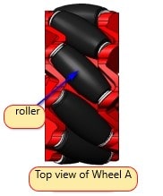
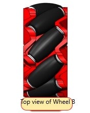
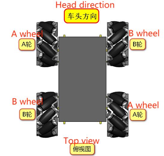
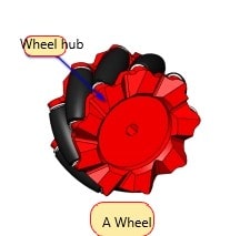
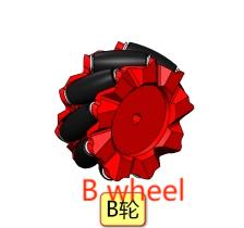
McNamee wheel (hereinafter referred to as McWheel) is composed of the hub and the rollers around the hub, the rollers are a kind of unpowered slave small rollers, McNamee wheel roller axis and hub axis angle is 45 degrees, and there are two kinds of mirror image of each other's A and B wheels, or it will be known as the left-handed wheel and right-handed wheel. This will generally be labeled A and B, L and R on the top of the hub.
imgimg

img img

14.1.2. McNamee Wheel Motion Analysis and Direction Determination

It was mentioned earlier that the McNamee wheel is divided into two kinds of AB, if the A wheel moves forward while moving to the right, i.e., moving diagonally to the right front, then on the contrary, the A wheel moves backward while moving to the left, i.e., moving diagonally to the left rear; accordingly, the B wheel can move diagonally to the left front and the right rear.

Taking the front of the cart as the positive direction, it is agreed that the direction when the wheel is moving forward is the forward rotation of the motor, and the direction when the wheel is moving backward is the reverse rotation of the motor. (All of the following lessons are illustrated in this direction)
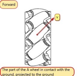
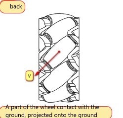
imgimg

Take the A wheel, the roller moving direction due to rolling and thus can not provide forward force, and in the direction of the roller axis roller can not roll and friction with the ground to produce the roller axis upward friction, that is, diagonal to the right before or after the direction of the left, and thus A wheel of the direction of the speed of the diagonal to the right before or after the left; Similarly, can analyze the B wheel.
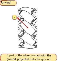
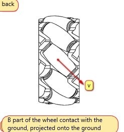
imgimg

From the physics we learned in high school, we know that velocity can be decomposed orthogonally, determining that the motion of the car depends on the direction of the combined velocity of the four wheels.

Then wheel A can be decomposed into velocity components that are axially to the right and vertically axially forward, or axially to the left and vertically axially backward.
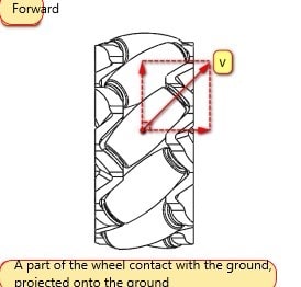
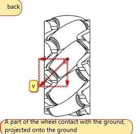
imgimg

In this way, the velocity components of the B wheel and the A wheel are now in a mirror image relationship with each other.
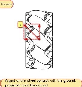
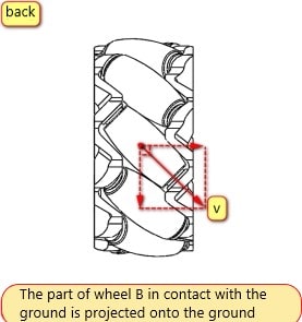
imgimg

14.1.3. McNamee Wheel Arrangement Combination and Motion Analysis

After knowing the velocity components of the AB wheels, we can arrange and combine the McNamee wheel chassis of the four wheels: AAAA, BBBB, AABB ......

Are all combinations capable of full range of motion? Not really.

Below we will give just one of the wrong examples and one of the right ones, and the rest can be reasoned out on their own (there are actually too many).

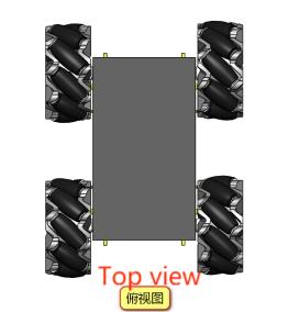
Analyzing the wrong example [AAAA]
imgimg

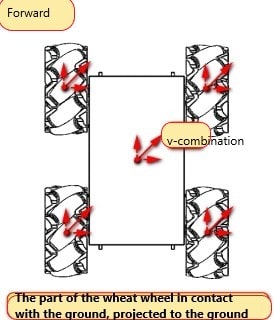
This one doesn't make sense at first glance, but let's analyze it anyway because as an example of a mistake, it's very easy to analyze what exactly is wrong with it. Earlier we talked about how the velocity components of the A wheels are either forward plus right or back plus left.

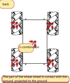
When all four wheels turn forward at the same time, each wheel will have a speed component to the left, which will lead to the whole chassis forward will necessarily move to the left at the same time; similarly, backward will necessarily move to the right, so there is no way to use it, this thing is uncontrolled to run around, which is not the omnidirectional movement we want.
imgimg

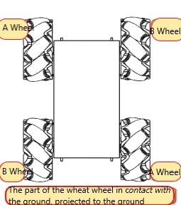
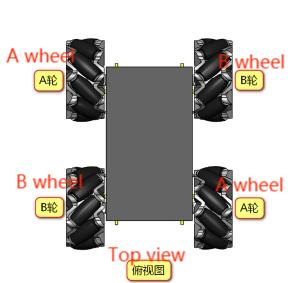
The correct distribution of wheat whorls should be [ABBA]
imgimg

When all four wheels are turned forward, the AB wheels can cancel each other's axial speed, leaving only the forward speed, so that the chassis is straight ahead and will not run away, and the same for backward;
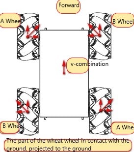
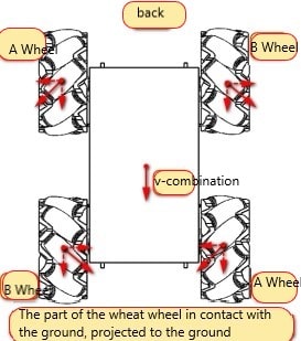
imgimg

If the forward and backward velocities cancel out when wheel A is spinning forward and wheel B is spinning backward, leaving only the velocity to the right, then the chassis will translate to the right;
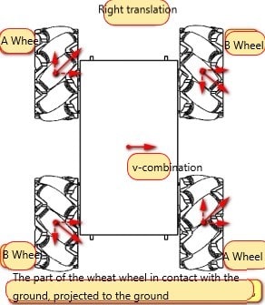
img

Conversely, if wheel A is reversed and wheel B is forward, it will pan to the left;
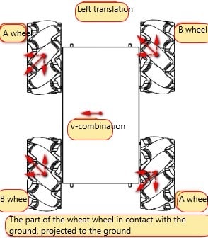
img

Finally the chassis will rotate to the right by turning the left wheel forward and the right wheel in reverse; conversely, the chassis will rotate to the left.
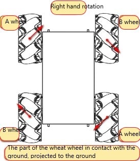
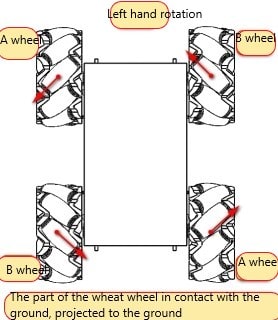
imgimg

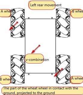
Also, when the A wheel is turned positively and the B wheel is not moving, the chassis moves to the right front;

The chassis moves to the left rear when the A wheel is reversed and the B wheel is not moving.
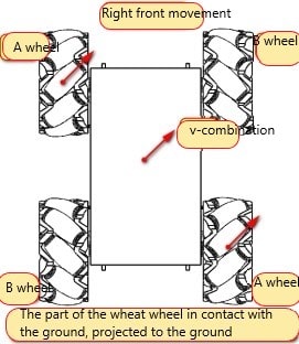
imgimg

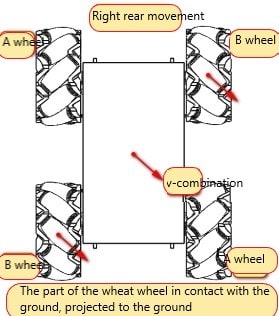
Accordingly, the chassis moves to the left front with the A wheel not moving and the B wheel rotating positively;

If the A wheel is not moving and the B wheel is reversed, the chassis moves to the right rear.
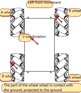
imgimg


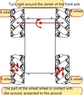
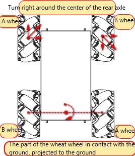
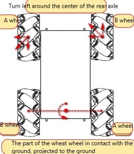
There are also four other ways to move around the midpoint of the axis.
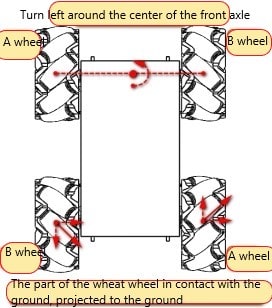
imgimg

imgimg

[Think] Aren't the above four cases very similar to translations, when the two wheels that are not moving move like a translation, but at a speed less than that of the other two wheels, how will the McNamee chassis move?

14.1.4. McNamee Wheel Mounting Positions

After we finished explaining the McNamee wheel mounting combinations earlier, there is more to be said about where to mount the four McNamee wheels.

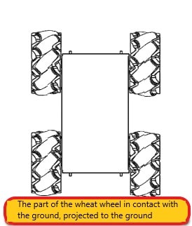
The shapes enclosed by the contact points of the four wheels with the ground are mainly squares and rectangles. Oddball shapes are not excluded, but only squares and rectangles will be analyzed here.

Square: The four wheels are located at the four vertices of a square, and there are no problems with translation and rotation. Due to the shape and size of the robot's chassis, this type of mounting is ideal but unattainable.
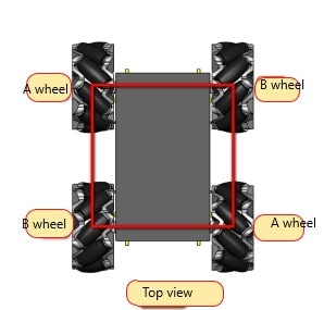
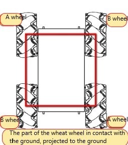
imgimg

The chassis we use with the addition of the Wheat Wheel is a carefully designed square, making it the ideal Wheat Wheel chassis.


Rectangular: Wheel rotation produces a Yaw axis torque, and the force arm of the torque is longer. It is the most common type of mounting.
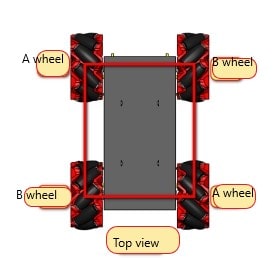

imgimg

By comparing the traditional vehicles, we can find that the wheels of ordinary vehicles are turning in one direction when moving, while the car using wheat wheels is doing omni-directional movement, as analyzed above, the direction of movement of each wheat wheel is different, so the wheat wheels want to do a real omni-directional movement, each wheat wheel needs a separate motor to drive, in this way, a set of control system is also needed to grasp the Each wheel's steering and rotation speed.

To realize omni-directional movement generally use omni-directional wheels and mcnemonic wheels, above we mainly introduced the mcwheel movement and installation combinations. Omni-directional wheels and McNamee wheels have differences in structure, mechanical properties, and kinematic properties, which is essentially due to the difference in the angle between the wheel hub axis and the roller rotating axis. After analyzing, the difference between the kinematic and mechanical characteristics of the two can be reflected by the following table.
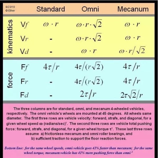
img

The calculations are shown below for reference only:
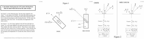
img

14.1.5 Final installation method

img


Theory of Robot Kinematics Analysis
Ackerman

COMPANY

  • About us
  • Team Style
  • Blog

LEARNING & EXPLORATION

  • Tutorials
  • Edge AI hardware
  • Educational robots
  • Embedded intelligent hardware

WHERE TO BUY

  • Yahboom Online Store
  • Amazon
  • Alibaba
  • AliExpress
  • Mercado

TECHNOLOGY SUPPORT

  • Email: support@yahboom.com

BE A DISTRIBUTOR

  • Email: sales@yahboom.com
QR Code
QR Code

Copyright © 2017-2026 Yahboom. All Rights Reserved.

EN/中文