yahboom
HomeLearn
Solution
Blog
Online Store
About Us
EN/中文
ROSMASTER R2📖
1.Preparation and First Trial
  • 1.1 Accessories introduction
  • 1.2 Precautions for battery
  • 1.3 First Trial
2.Assembly steps
  • Installaction Video
3.ROS1-Remote control course
  • 3.1 APP remote control
  • 3.2 Model aircraft remote control
  • 3.3 Handle remote control
4.ROS1-Hardware course
  • 4.1 About expansion board_V3.0
  • 4.1 About expansion board_V1.0
  • 4.2 STM32 Development environment
  • 4.3 Button to control the buzzer to whistle
  • 4.4 FreeRTOS application
  • 4.5 Serial communication
  • 4.6 SBUS model aircraft remote control
  • 4.7 CAN bus communication
  • 4.8 RGB colorful light bar
  • 4.9 Timer interrupt to control PWM servo
  • 4.10 Control serial port servos
  • 4.11 Nine-axis attitude sensor to obtain data
  • 4.12 Control motor
  • 4.13 Timer captures the encoder data
  • 4.14.1 Kinematic Analysis of Mecanum Wheel
  • 4.14.2 Kinematics Analysis of Ackermann Car
  • 4.15 PID control robot movement
5.ROS1-Basic course
  • 5.1 Update the firmware
  • 5.2 Turn off the self-starting process at startup
  • 5.3 Install the Rosmaster driver library
  • 5.4 Buzzer whistle
  • 5.5 Control PWM servo
  • 5.6 RGB colorful light bar special effects display
  • 5.7 Control motor
  • 5.8 Control robot movement
  • 5.9 Control Serial Servo
6.ROS1-Linux operating system
  • 6.1 Virtual machine installation and use
  • 6.2 Linux basics
  • 6.3 Remote control
  • 6.4 Multi-machine communication configuration
  • 6.5 Static IP and hotspot mode
  • 6.6 Bind the device ID
  • 6.7 Web page real-time monitoring
  • 6.8 Expansion tutorial
  • 6.9.1 Jetson Nano write sytem
  • 6.9.2 Jetson Xavier NX write system
  • 6.9.3 Jetson TX2 NX write system
  • 6.9.4 Raspberry Pi write system
7.ROS1-Docker-pi5
  • 1、Docker overview and docker installation
  • 2、Common commands for docker image containers
  • 3、Docker images deeply understand and publish images
  • 4、Docker hardware interaction and data processing
  • 5、Enter the bot's docker container
  • 6、Robot development environment construction in Docker
  • 7、How customers can update docker images in the future
8.ROS1-ROS basic course
  • 1.ROS introduction
  • 2.ROS installation
  • 3.ROS common command tools
  • 4.ROS workspace
  • 5.ROS function package
  • 6.ROS node
  • 7.ROS topic publisher
  • 8.ROS topic subscribers
  • 9.ROS service client
  • 10.ROS service server
  • 11.ROS action client
  • 12.ROS action server
  • 13.ROS custom message reception
  • 14.ROS-launch file
  • 15.ROS-TF transformation
  • 16.ROS parameter service
  • 17.ROS-rviz use
  • 18.ROS-rqt tool usage
  • 19.Topic message recording and playback
  • 20.urdf model introduction
  • 21.gazebo introduction
  • 22.ROS distributed communication
9.ROS1-OpenCV courses
  • 9.1 Getting started with Open Source CV
  • 9.2 Geometric transformation
  • 9.3 Image processing and drawing text line segments
  • 9.4 Image beautification
  • 9.5 Opencv application
  • 9.6 AR vision
  • 9.7 AR QR code
  • 9.8 ROS+Opencv foundation
  • 9.9 ROS+Opencv application
  • 9.10 Data transformation and point cloud
  • 9.11 MediaPipe development
10.ROS1-Robot control course
  • 10.1 PID algorithm theory
  • 10.2 Robot PID debugging
  • 10.3 Robot information release
  • 10.4 Robot keyboard control
  • 10.5 Robot handle control
  • 10.6 Robot state estimation
  • 10.7 Robot calibration
  • 10.8 Robot URDF model
11.ROS1-Depth camera course
  • 11.1 How to use the Astra camera
  • 11.2 Astra camera calibration
  • 11.3 Astra Color Tracking
  • 11.4 Astra Object Tracking
  • 11.5 Visual tracking autopilot
  • 11.6 Pure visual 2D mapping and navigation
  • 11.7 RTAB-Map 3D mapping navigation
  • 11.8 ORB_SLAM2 basics
  • 11.9 ORB_SLAM2_Octomap
12.ROS1-Lidar course
  • 11.1 Lidar basic-SLAM
  • 11.1 Lidar basic-EAI
  • 11.2 Lidar avoiding
  • 11.3 Lidar guard
  • 11.4 Lidar follow
  • 11.5 Patrol game
  • 11.6 gmapping mapping
  • 11.7 hector mapping
  • 11.8 karto mapping
  • 11.9 cartographer mapping
  • 11.10 rrt_exploration mappin
  • 11.11 AMCL
  • 11.12 Navigation and avoiding
  • 11.13 APP mapping and navigation
  • 11.14 TEB path planning algorithm
13.ROS1-Multi-robot control course
  • 13.1 Multi-machine handle control
  • 13.2 Multi-machine navigation
  • 13.3 Multi-machine formation
  • 13.4 Multi-machine surround
14.ROS1-Deep learning courses
  • 14.1 KNN recognizes handwritten digits
  • 14.2 Basic use of TensorFlow
  • 14.3 Basic use of PyTorch(jetson)
  • 14.4 yolov5 model training(jetson)
  • 14.5 yolov5+tensorrt acceleration(jetson)
  • 14.6 yolov4-tiny
15.ROS1-Voice control courses
  • 15.0 How to use old voice module in new image
  • 15.1 Introduction of voice control module-NEW
  • 15.2 Voice control module port binding-NEW
  • 15.1 Introduction of voice control module-Old
  • 15.2 Voice control module port binding-Old
  • 15.3 Voice control car movement
  • 15.4 Voice control Autopilot
  • 14.5 Voice control color recognition
  • 15.6 Voice control color tracking
  • 15.7 Voice control multi-point navigation
16.ROS1-Model training Autopilot
  • 16.0 ReadMe
  • 16.1 yolov5 to train traffic signs
  • 16.2 TensorRt acceleration identification mark
  • 16.3 Road sign indication function description
  • 16.4 Collect data
  • 16.5 Training model
  • 16.6 Model transformation and application
  • 16.7 AI Autopilot
17. ROS2-Remote control course
  • 1. APP remote control
  • 2. Model aircraft remote control
  • 3. Handle remote control
18.ROS2-Hardware course
  • 1. Expansion board introduction_V3.0
  • 1. Expansion board introduction_V1.0
  • 2. STM32 development environment build
  • 3. Key control buzzer sounding
  • 4. FreeRTOS applications
  • 5. Serial communication
  • 6. SBUS model airplane remote control
  • 7. CAN bus communication
  • 8. RGB colorful light bar
  • 9. Timer interrupt control PWM servos
  • 10. Control serial servos
  • 11. Nine-axis attitude sensor acquires data
  • 12. Control motor forward and reverse
  • 13. Timer Capture Encoder Data
  • 14. Theory of Robot Kinematics Analysis
  • 14.1.Mecanum wheel
  • 14.2.Ackerman
  • 14.3.4WD
  • 15. PID control of robot motion
19. ROS2-Basic course
  • 1. Update the firmware of the expansion board
  • 2.Close the large self-starting program at boot
  • 3. Install Rosmaster driver library
  • 4. Buzzer sounding
  • 5. Control PWM servo
  • 6. RGB colorful light bar special effects show
  • 7. Control motor forward and reverse
  • 8. Controlling robot motion
  • 9. Control serial servos
20. ROS2-Linux operating systemnew
  • 01. Virtual Machines
  • 02. Linux Basics
  • 03. Remote control
  • 04. Multi-computer communication configuration
  • 05. Static ip and hotspot mode
  • 06. Bind device ID
  • 07.Webpage real-time monitoring
  • 08. Expansion Tutorial
  • 09-1.Jetson Nano write system file
  • 09-2. Raspberry Pi write system file
  • 09-3.Orin write system
  • 10.Jetpack old system upgraded to SUPER systemnew
21.ROS2 -Docker(Nano Pi)
  • 1. docker overview and docker installation
  • 2. docker image container common command
  • 3. docker image in-depth understanding and publishing images
  • 4. docker hardware interaction and data processing
  • 5. Enter the docker container of the robot
  • 6. docker in the robot development environment build
  • 7. Customer's method of updating docker images in the future
22.ROS2- ROS2 Basic Tutorial
  • 1.Introduction to ROS2
  • 2.ROS2 install Humble
  • 3.ROS2 development environment
  • 4.ROS2 workspace
  • 5.ROS2 function package
  • 6.ROS2 node
  • 7.ROS2 topic communication
  • 8.ROS2 service communication
  • 9.ROS2 action communication
  • 10.ROS2 custom interface message
  • 11.ROS2 parameter service case
  • 12.ROS2 meta-function package
  • 13.ROS2 distributed communication
  • 14.ROS2 DDS
  • 15.ROS2 time related API
  • 16.ROS2 common command tools
  • 17.ROS2 rviz2 use
  • 18.ROS2 Rqt Toolbox
  • 19.ROS2 Launch startup file configuration
  • 20.ROS2 recording and playback tool
  • 21.ROS2 URDF model
  • 22.ROS2 Gazebo simulation platform
  • 23.ROS2 TF2 coordinate transformation
23. ROS2-Robot control course
  • 1. PID algorithm theory
  • 2. Robot information release
  • 3. Robot control
  • 4. Robot state estimation
  • 5. Robot calibration
  • 6. URDF model
24. ROS2-Lidar course
  • 1-1. Introduction and use of SLAM lidar
  • 1-2. Introduction and use of 4ROS lidar
  • 2. Lidar obstacle avoidance fun gameplay
  • 3. Lidar tracking fun gameplay
  • 4. Patrol function play
  • 5. gmapping map building algorithm
  • 6. cartographer building algorithm
  • 7. Navigation and obstacle avoidance
  • 8. Rosmaster_R2 using the app to build maps
  • 9. Rosmaster_R2 navigating with the app
25. ROS2-OpenCV courses
  • 1. opencv basic course
  • 2. ROS+opencv application
  • 3. QR code creation and recognition
  • 4. AR Vision
  • 5. mediapipe fun gameplay
  • 6. Patrol line autopilot
26. ROS2-Depth camera courses
  • 1. Depth camera use
  • 2. Camera calibration
  • 3. Color tracking
  • 4. KCF object tracking
  • 5. ORB_SLAM2 Basics
  • 6. ORB_SLAM2 PCL mapping
  • 7. ORB_SLAM2 Octomap mapping
  • 8. RTAB-Map 3D mapping navigation
27.ROS2- Voice control courses
  • 0. How to use old voice module in new image
  • 1.1 Introduction to the module-New
  • 1.2 Voice Control Module Port Binding-New
  • 1.3 Introduction to the module-Old
  • 2. Voice control car movement
  • 3. Voice control autopilot
  • 4. Voice control color recognition
  • 5. Voice control color tracking
  • 6. Voice control multi-point navigation
28.Deep learning courses(SUPER)
  • 1.KNN recognizes handwritten digitsnew
  • 2.Basic use of TensorFlownew
  • 3.Basic use of PyTorch(jetson)new
  • 4.YOLOv11Model conversion(SUPER)new
  • 5.YOLOv11Dataset annotation(SUPER)new
  • 6.YOLOv11Model conversion + tensorrt acceleration(SUPER)new
  • 7.YOLOv11Object recognition(SUPER)new
29. ROS2-Multi-robot control
  • 1. Multi-robot control
  • 2. Multi-robot navigation
LLM tutorial
1.Development environment
  • 0. Model usage instructions
  • 1.Environments deployment
  • 2.Dialogue platform installation
2.Jetson Nano B01
  • 1.Qwen2 model
  • 2.TinyLlama model
  • 3.Phi-3 model
  • 4.Gemma model
  • 5.Orca Mini model
  • 6.StarCoder2 model
  • 7.DeepSeek-R1 model
  • 8.Expand LLaVA-Phi3
3.Jetson Orin NXNANO
  • 1.Llama3 model
  • 2.Qwen2 model
  • 3.Phi-3 model
  • 4.Gemma model
  • 5.WizardLM2 model
  • 6.Codellama model
  • 7.DeepSeek-R1 model
  • 8.Orca Mini model
  • 9.StarCoder2 model
  • 10.TinyLlama model
  • 11.Expand LLaVA
  • 12.Expand LLaVA-Phi3
4.Raspberry Pi 5B
  • 1.Meta AI Llama3 model
  • 2.Qwen2 model
  • 3.Phi-3 model
  • 4.Gemma model
  • 5.WizardLM2 model
  • 6.Meta AI Codellama model
  • 7.DeepSeek-R1 model
  • 8.Expand LLaVA
FAQ
  • 1.Using your own Jetson board, car cannot start normally
Download
  • RemoteCtrl_APP(iOS/Android)
  • Mapping_APP(iOS_Android)
  • Instruction Manual
  • SystemFile_ROS1
  • SystemFile_ROS2
  • SystemFile_ROS2_OrinNANOSUPER
  • SystemFile_ROS2_OrinNXSUPER
  • VM software
  • Code
  • Jetson_Boot_USB.tar.gz
  • Autopilot Annex
  • Other_Annex_File
  • LLM_SystemFile
  • ROS2_Basic_VM
Download ZIP

Welcome to ROSMASTER R2 repository

2. STM32 development environment build

2. STM32 development environment build

2. STM32 development environment build2.1 Introduction to STM32CubeIDE2.2 Download the installation package2.3 Starting Installation2. 4. New project2.5 Pin configuration2.6. Writing the code2. 7 Compile the program2.8. Burning program2.9. Program Phenomena

2.1 Introduction to STM32CubeIDE

STM32CubeIDE is an all-in-one multi-operating system development tool, an advanced C/C++ development platform with peripheral configuration, code generation, code compilation and debugging for STM32 microcontrollers and microprocessors. It is based on the Eclipse®/CDT™ framework and the GCC tool chain for development, as well as GDB for debugging. It can select an STM32 microprocessor and then create a project and generate the initialization code to support graphical configuration of STM32 clocks and pins and other content, support for the mainstream platforms of Windows, Linux, Mac, very powerful and practical features.


2.2 Download the installation package

Open the following link with your computer browser:

https://www.st.com/zh/development-tools/stm32cubeide.html

Download according to the computer system, here to Win10 system to install version 1.9.0 as an example, select the latest version to download.
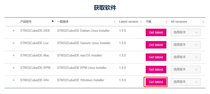
image-20220309095106970

If you have an account on my.st.com, you can log in and download the software directly. If you don't want to log in now, just provide your name and email address in the form below to download the software.

Unzip the downloaded file, and unzip the path without Chinese.

image-20220309100601767

2.3 Starting Installation

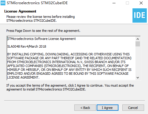
Double click to open the installation package. Then just follow the tutorial.
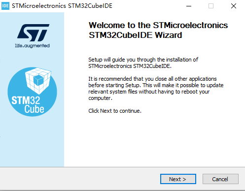
image-20220309100702670

image-20220309100727187

Installation path can be modified according to the actual self, pay attention to do not have Chinese.
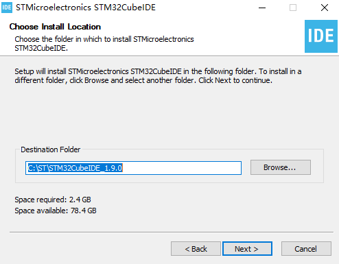
image-20220309100759937

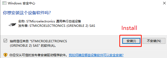
Check the driver and then click Install to install it.
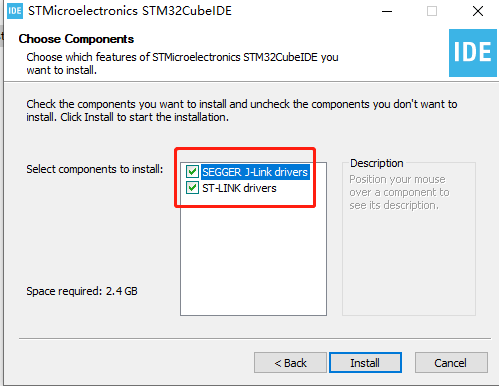
image-20220309100939458

image-20220309101103308

Next just wait for the installation to complete.
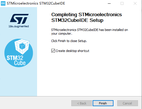
image-20220309101409033

2. 4. New project

  1. Double-click the desktop shortcut to open STM32CubeIDE, you need to select the workspace, save the path can be based on the actual choice of other paths (do not bring Chinese).

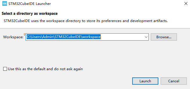
 

image-20220309101938781

image-20220309103807055

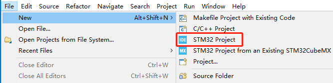
  1. Click File->New->STM32 Project.

image-20220309103950961

  1. Search and select the chip STM32F103RCT6, then click Next in the lower right corner to go to the next step.
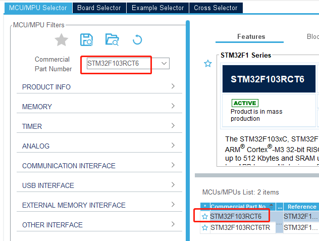
image-20220309104523552

  1. Enter the name of the project, here to LED as an example, other parameters can be default.
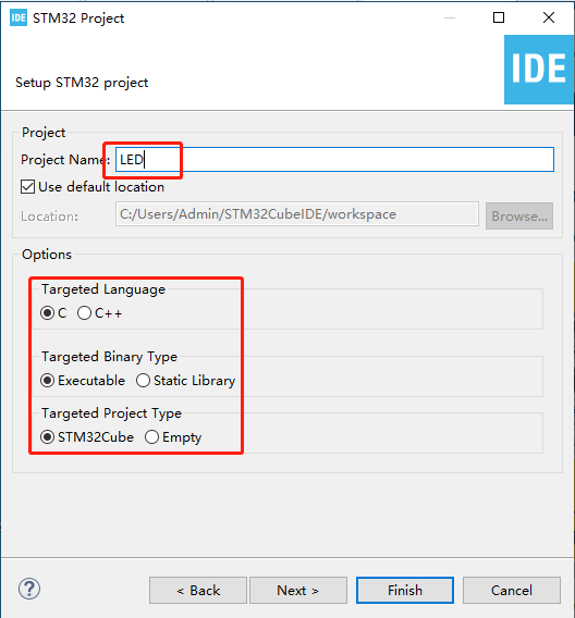
image-20220309104753828

  1. Click Yes and the graphical content will be loaded at this point.
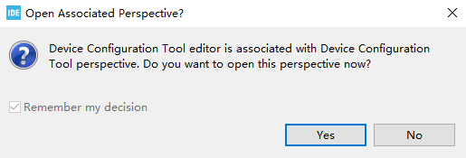
image-20220309104926020

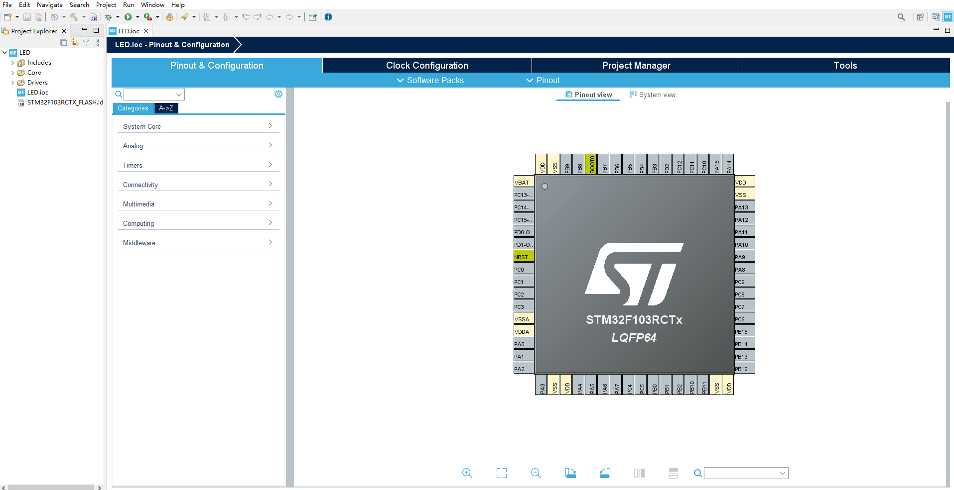
When completed, it is shown below:

image-20220309105514825

2.5 Pin configuration

  1. First of all, you need Debug information, under Pinout&Configuration, click SYS->Debug to select Serial Wire.
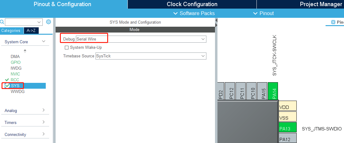
image-20220309111832426

  1. Modify the system clock of STM32, according to the schematic diagram, we can see that the external crystal is 8M frequency.
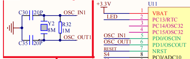
image-20220309110118096

In Pinout&Configuration select RCC->HSE select Crystal/Ceramic Resonator where HSE is the external clock and LSE is the internal clock, using the external clock can be more stable and efficient than the internal clock.
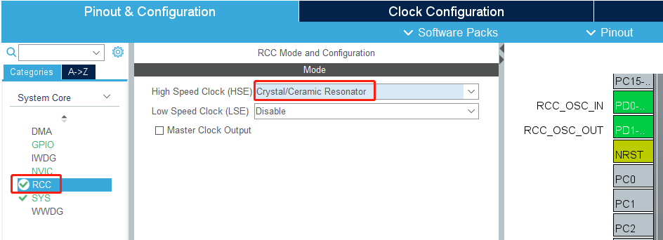
image-20220309110240836

Switch to Clock Configuration to modify the frequency of HCLK to 72 and press Enter to confirm.
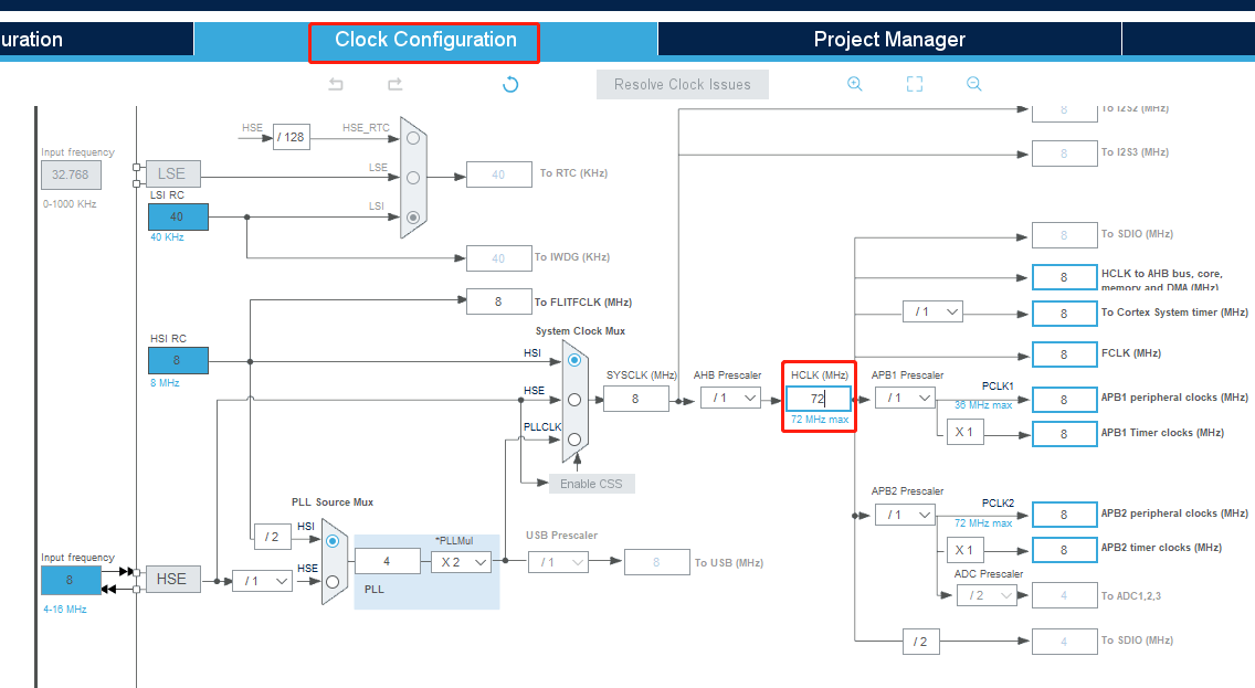
image-20220309110757303

image-20220309110728487

  1. Increase the LED pin configuration, from the schematic diagram it can be seen that the LED is connected to the PC13 pin.
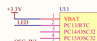
image-20220309112325122

Set the PC13 pin to GPIO_Output, and for convenience here change the Label to LED.
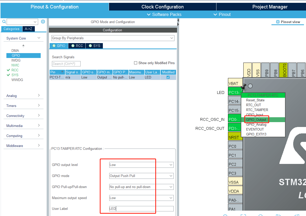
image-20220309112613410

Then press Ctrl+S to save, check Remember my decision, and click Yes. This will automatically generate the code every time you save.
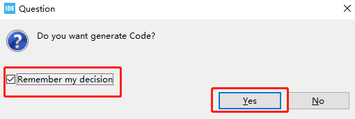
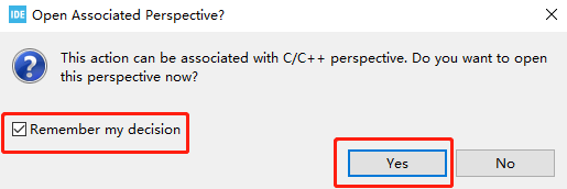
image-20220309112812784

image-20220309112931421

2.6. Writing the code

  1. Since the previous step of graphical configuration has generated the initialization code of the system, we only need to add the functions to be implemented.

Find the main function in the main.c file and add the control LED under while (1). The function is to flash the LED every two hundred milliseconds. Press Ctrl+S to save the code.
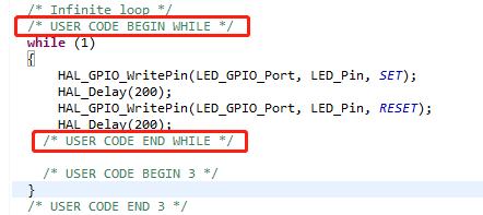
image-20220309114143099

Note: The code content should be added between USER CODE BEGIN and USER CODE END. Otherwise, the code content will be overwritten next time when you generate the code through the graphical tool, but it will not be overwritten if you add it between USER CODE BEGIN and USER CODE END. Don't write Chinese comments in it, it may be messy.

2. 7 Compile the program

  1. Add the function of generating HEX files.

Click Project->Properties->C/C++ Build->Settings->MCU Post build outputs in order, and then tick the box in front of Convert to Intel Hex file(-O ihex), as shown below.
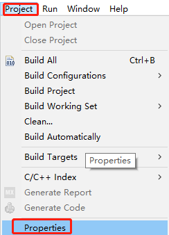
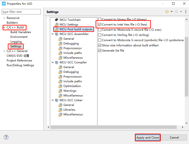
image-20220401105445775

image-20220401105123327

  1. Click the hammer in the toolbar to start compiling the project.

image-20220401105951706

STM32CubeIDE will pop up the Console console, see compile 0 error, 0 warning means compile successfully. As shown in the figure below, the project generates a file named LED.hex, and this file is saved in the Debug folder of the project directory.
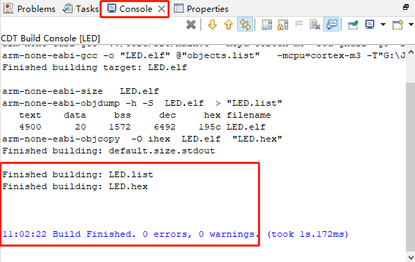
image-20220401110314069

2.8. Burning program

1.Install CH340 driver

As the USB communication of Rosmaster expansion board uses CH340 chip, so you need to install the driver of CH340 chip, if your computer has already installed CH340 driver, you don't need to repeat the installation.

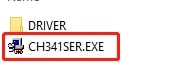
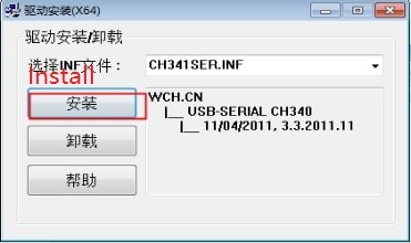
Unzip this course material in the [Uart drive (CH340).zip], double-click to open the CH341SER.EXE program
img

Click Install and the installation will be prompted as successful when it is complete.
img

  1. Download burning software

This burning Rosmaster expansion board MCU firmware need to use mcuisp (or flymcu) burning software, please go to http://www.mcuisp.com download mcuisp (or flymcu) burning software; you can also directly use the information provided in the mcuisp software.

mcuisp software is a green version of the software, do not need to install, double-click to open to use.

3.Connecting the device

Before connecting the Rosmaster to your computer, unplug the micro USB cable and power cable that connects the expansion board to the Jetson Nano.

Plug one end of the USB cable into the USB port of your computer and the other end into the Micro USB port of the Rosmaster expansion board.
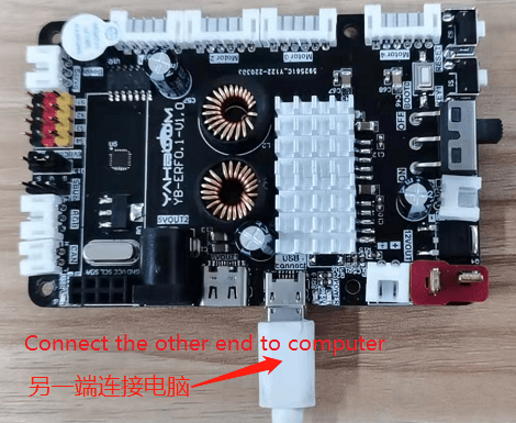
image-20220401112853890

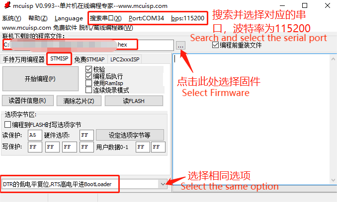
  1. Configure the burning software

image-20220325110607466

When searching serial ports, if there are more than one serial port number, and you can't confirm which one is Rosmaster's. Solution 1: Unplug the other USB port and search again; Solution 2: Unplug the USB cable of Rosmaster first, click Search Serial Port, write down the serial port number searched, plug in the USB cable of Rosmaster, search the serial port again, and compare before and after two times, the newly added serial port number is the serial port number of Rosmaster.

To select the firmware, you need to select the LED.hex file in the Debug folder of the project directory.

Finally, the bottom of the configuration selection, be sure to select [DTR's low level reset, RTS high level into the BootLoader] option, otherwise it may lead to download failure.

  1. Burning Program

Please first put the microcontroller on the expansion board into the burn mode:

First press and hold the BOOT0 key on the expansion board, then press the RESET key, and finally release the BOOT0 key.
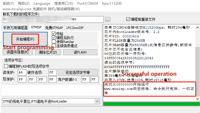
image-20220325111504124

Click [Start Programming], the mcuisp burning software will burn the firmware we chose in the previous step to the microcontroller on Rosmaster's expansion board. When the prompt [Successfully run www.mcuisp.com Reporting to you. from 08000000, the command is executed, everything is normal] appears on the right side, it means the download is successful.

Note:

① Before you start burning, please make sure that the serial port number of Rosmaster is accessible, that is, no serial assistant occupies it.

② Rosmaster into the burning mode of operation, first press and hold the BOOT0 key on the expansion board, then press the RESET key, and finally release the BOOT0 key.

2.9. Program Phenomena

The LED on the expansion board flashes every 200 milliseconds.

Expansion board introduction_V1.0
Key control buzzer sounding

COMPANY

  • About us
  • Team Style
  • Blog

LEARNING & EXPLORATION

  • Tutorials
  • Edge AI hardware
  • Educational robots
  • Embedded intelligent hardware

WHERE TO BUY

  • Yahboom Online Store
  • Amazon
  • Alibaba
  • AliExpress
  • Mercado

TECHNOLOGY SUPPORT

  • Email: support@yahboom.com

BE A DISTRIBUTOR

  • Email: sales@yahboom.com
QR Code
QR Code

Copyright © 2017-2026 Yahboom. All Rights Reserved.

EN/中文