Welcome to ROSMASTER R2 repository
11.14 TEB path planning algorithm
14. TEB path planning algorithm
14.1. Introduction
The full English name of ted is Time Elastic Band. It performs subsequent modification on the initial trajectory generated by the global path planner to optimize the motion trajectory of the robot, which belongs to local path planning. During the trajectory optimization process, the algorithm has various optimization objectives, including but not limited to: overall path length, trajectory running time, distance to obstacles, passing through intermediate path points and robot dynamics, kinematics and compliance with geometric constraints.
The popular explanation is that the local trajectory generated by TEB is composed of a series of discrete poses with time information. The goal of g2o algorithm optimization is these discrete poses,So that the final trajectory composed of these discrete poses can achieve the goals of the shortest time, the shortest distance, and away from obstacles, etc.,At the same time, the speed and acceleration are limited so that the trajectory meets the kinematics of the robot.It should be pointed out that the results of g2o optimization do not necessarily meet the constraints, that is, they are actually soft constraints. If the parameter settings are unreasonable or the environment is too harsh, teb may fail and plan a very strange trajectory.Therefore, the conflict detection part is included in the teb algorithm. After the trajectory is generated, it is judged point by point whether the points on the trajectory conflict with the obstacle. This process takes the actual outline of the robot into consideration.
14.2. Comparison of teb algorithm and dwa algorithm
The DWA algorithm is commonly used, and the target robot model is a differential robot, or an omnidirectional robot, which can at least rotate in situ. However, R2 is a car model belonging to the Ackerman model, so the dwa algorithm does not apply to R2. The DWA algorithm has a contradictory point, that is, due to the mismatch of the target model, it is impossible to set the very important parameter of the steering radius.
teb will adjust its own posture orientation during the movement process. When it reaches the target point, usually the orientation of the robot is also the target facing without needing to rotate; dwa is reaches the target coordinate point first , then rotate in place to the target facing. This is where there is a clear difference between the two. For a two-wheel differential chassis, teb adjusting the orientation in motion will make the motion path unsmooth**, and there will be unnecessary backing when starting and when it will reach the target point. This is not allowed in some application scenarios.
14.3. teb parameter adjustment
It can be seen from the above that if you want the path planned by teb to travel more smoothly, you need to adjust the parameters. There are still quite a few parameters for teb path planning. Here is the meaning of each parameter.
14.3.1. The parameters in the Trajectory section are used to adjust the trajectory
# Trajectory teb_autosizeTrue dt_ref0.3 dt_hysteresis0.1 max_samples500 global_plan_overwrite_orientationTrue allow_init_with_backwards_motionTrue max_global_plan_lookahead_dist6 global_plan_viapoint_sep-1 global_plan_prune_distance1 exact_arc_lengthFalse feasibility_check_no_poses2 publish_feedbackFalse| Parameter | Meaning |
|---|---|
| dt_ref | Desired trajectory time resolution |
| dt_hysteresis | Automatically resize the phenomenon of hysteresis based on current time resolution |
| global_plan_overwrite_orientation | Overrides the orientation of local subgoals provided by the global planner |
| max_samples | Maximum number of samples |
| max_global_plan_lookahead_dist | Specifies the maximum length of a subset of global plans to consider for optimization |
| allow_init_with_backwards_motion | Whether to initialize before planning the path Including reversing action |
| global_plan_viapoint_sep | Minimum interval between every two consecutive passing points selected from the global path |
| publish_feedback | Publish planner feedback with full trajectory and active obstacle list |
| global_plan_prune_distance | This parameter determines to start cropping from a certain distance behind the current position of the robot |
| exact_arc_length | If true, the planner uses the exact arc length [increased CPU time] in velocity, acceleration and turn rate calculations, otherwise uses the Euclidean approximation. |
| feasibility_check_no_poses | It is used when judging whether the generated trajectory collides, and it is set to 3 at this time, that is, the 3 points on the trajectory are checked one by one from the starting point of the trajectory. If none of the three points collide, the trajectory is considered valid. If less than 0 all waypoints are checked. |
14.3.2. The parameters of the Robot part set the structure parameters and speed parameters of the robot
xxxxxxxxxx # Robot max_vel_x0.4 max_vel_x_backwards0.4 max_vel_y0.0 max_vel_theta1.0 # the angular velocity is also bounded by min_turning_radius in case of a carlike robot (r = v / omega) acc_lim_x0.5 acc_lim_theta0.5 # ********************** Carlike robot parameters ******************** min_turning_radius0.768 # Min turning radius of the carlike robot (compute value using a model or adjust with rqt_reconfigure manually) wheelbase0.25 # Wheelbase of our robot cmd_angle_instead_rotvelFalse # stage simulator takes the angle instead of the rotvel as input (twist message) # ********************************************************************| Parameter | Meaning |
|---|---|
| max_vel_x | Maximum speed in the x-axis direction |
| max_vel_x_backwards | Maximum reversing speed in the x-axis direction |
| acc_lim_x | Acceleration limited in the x-axis direction |
| max_vel_theta | Maximum turning speed |
| acc_lim_theta | Turning acceleration limit |
| min_turning_radius | Minimum turning radius (experience value is 2.4* car length) |
| wheelbase | Wheelbase |
14.3.3. GoalTolerance part of the parameter setting target error
xxxxxxxxxx # GoalTolerance xy_goal_tolerance0.2 yaw_goal_tolerance0.2 free_goal_velFalse| Parameter | Meaning |
|---|---|
| xy_goal_tolerance | Allowable distance error of target position |
| yaw_goal_tolerance | Allowable angular error of target position |
| free_goal_vel | Whether to remove the constraint of target speed |
14.3.4. The parameter setting of the Obstacles part of the obstacle processing
xxxxxxxxxx # Obstacles min_obstacle_dist0.2 # This value must also include our robot's expansion, since footprint_model is set to "line". inflation_dist0.5 include_costmap_obstaclesTrue costmap_obstacles_behind_robot_dist1.0 obstacle_poses_affected20 dynamic_obstacle_inflation_dist0.6 include_dynamic_obstaclesTrue costmap_converter_plugin"" costmap_converter_spin_threadTrue costmap_converter_rate8| Parameter | Meaning |
|---|---|
| min_obstacle_dist | Minimum expected distance to obstacles |
| inflation_dist | Buffer zone around obstacles |
| include_costmap_obstacles | Whether to take into account the obstacles of the local costmap |
| costmap_obstacles_behind_robot_dist | Consider obstacles within n meters behind |
| costmap_converter_spin_thread | If true, the costmap converter will call its callback queue in a different thread, |
| costmap_converter_rate | The frequency with which the costmap_converter plugin processes the current costmap |
| obstacle_poses_affected | Obstacle attitude affected degree 0-30 |
| dynamic_obstacle_inflation_dist | Expansion range of dynamic obstacles |
| include_dynamic_obstacles | Whether to predict dynamic obstacles as a speed model |
14.3.5.Optimization part of the parameters set the weight size in the path planning
xxxxxxxxxx # Optimization no_inner_iterations5 no_outer_iterations4 optimization_activateTrue optimization_verboseFalse penalty_epsilon0.1 obstacle_cost_exponent4 weight_max_vel_x2 weight_max_vel_theta1 weight_acc_lim_x1 weight_acc_lim_theta1 weight_kinematics_nh1000 weight_kinematics_forward_drive1 weight_kinematics_turning_radius1 weight_optimaltime1 # must be > 0 weight_shortest_path0 weight_obstacle100 weight_inflation0.2 weight_dynamic_obstacle10 # not in use yet weight_dynamic_obstacle_inflation0.2 weight_viapoint1 weight_adapt_factor2| Parameter | Meaning |
|---|---|
| no_inner_iterations | Number of times the inner loop performs optimization after being called by the outer loop |
| no_outer_iterations | The number of optimizations of the outer loop executed The number of optimizations of the outer loop executed |
| optimization_activate | whether to activate the optimization |
| optimization_verbose | Whether to print the optimization process details |
| penalty_epsilon | For hard-constrained approximations, add a safety margin to the penalty function |
| weight_max_vel_x | Maximum x speed weight 0~2 |
| weight_max_vel_theta | Maximum angular speed weight 0~1 |
| weight_acc_lim_x | Maximum x acceleration weight 0~1 |
| weight_acc_lim_theta | Maximum angular speed weight 0~1 |
| weight_kinematics_nh | Optimal weights to satisfy non-holographic kinematics |
| weight_kinematics_forward_drive | In the optimization process, the robot is forced to choose only the forward direction, and the differential wheel is suitable |
| weight_kinematics_turning_radius | During the optimization process, the weight of the minimum turning radius of the model robot |
| weight_optimaltime | Trajectory-based temporal weights during optimization |
| weight_obstacle | During the optimization process, the weight of the minimum distance from the obstacle is 0~50 |
| weight_inflation | During the optimization process, the weight of the inflated region |
| weight_dynamic_obstacle | During the optimization process, the weight of the minimum distance from the dynamic obstacle |
| weight_dynamic_obstacle_inflation | During the optimization process, the weight of the dynamic obstacle expansion area is 0~50. |
| weight_viapoint | During the optimization process, the weight of the distance from the global path sampling point |
14.3.6, Homotopy Class Planner some parameters
xxxxxxxxxx enable_homotopy_class_planningTrue enable_multithreadingTrue roadmap_graph_no_samples15 roadmap_graph_area_width5 h_signature_prescaler0.5 h_signature_threshold0.1 obstacle_heading_threshold0.45 switching_blocking_period0.0 visualize_hc_graphFalse visualize_with_time_as_z_axis_scaleFalse| Parameter | Meaning |
|---|---|
| enable_homotopy_class_planning | Whether to activate parallel planning |
| enable_multithreading | Whether to allow multi-threaded parallel processing |
| roadmap_graph_no_samples | Specify the number of samples to generate for roadmap creation |
| roadmap_graph_area_width | Specifies the width of the area |
| h_signature_prescaler | Scaling the internal parameters used to differentiate homotopy classes |
| h_signature_threshold | Two h signatures are assumed to be equal if the difference between the real and complex parts are both below a specified threshold |
| obstacle_heading_threshold | Specifies the value of the scalar product between the obstacle heading and the target heading to explore taking the obstacle into account |
| switching_blocking_period | Duration that needs to be terminated before switching to a new equivalent class is allowed |
| visualize_hc_graph | Whether to visualize created graphs for exploring different trajectories |
| visualize_with_time_as_z_axis_scale | Whether you can see the optimized graph in rviz |
14.4. Use the parameter adjuster to debug teb parameters
After the navigation is turned on, if we are not satisfied with the effect of the navigation, we can use the parameter adjuster to dynamically debug the parameters, input the terminal,
xxxxxxxxxxrosrun rqt_reconfigure rqt_reconfigure
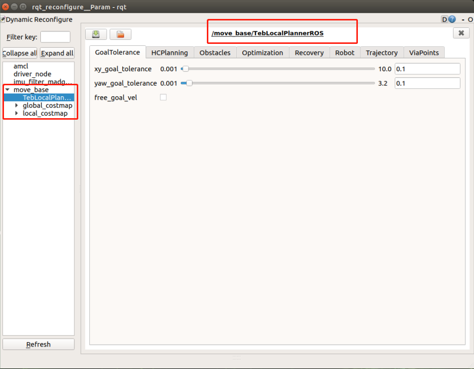
Generally speaking, the minimum turning radius of min_turning_radius is 2.4 times the length of the vehicle;The wheelbase parameter needs to be actually calibrated, the distance between the drive shaft and the rotating shaft.Other parameters are debugged according to the actual situation.The parameters in this part of Optimization are aimed at optimizing the navigation effect,Among them, the weight value of weight_kinematics_forward_drive is to force the car to move forward without reversing.Experience tells us that when this value is adjusted to the maximum, there is no way to completely prohibit the effect of reversing.Whether the car can move forward is determined by combining other parameters.
For more explanation of parameters, you can refer to the official documentation reference: