Welcome to ROSMASTER R2 repository
6. SBUS model airplane remote control
6. SBUS model airplane remote control
6. SBUS model airplane remote control6.1. Purpose of the experiment6.2 Configuring Pin Information6.3. Experimental flow chart analysis6.4. Core code explanation6.5 Hardware Connection6.6 Experimental effect
6.1. Purpose of the experiment
Use the serial communication of STM32 to parse the SBUS protocol data transmitted by the air model RC transmitter and print the values of each channel.
6.2 Configuring Pin Information
- Import the ioc file from Serial's project and name it SBUS.
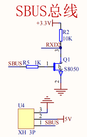
According to the schematic diagram, SBUS is connected to the RX pin of serial port 2, which only receives but does not transmit.

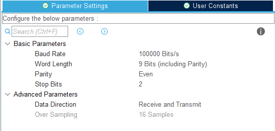
- Modify the mode of serial port 2 to Asynchronous synchronous communication, baud rate is 100000, data width: 9 bits, check: Even, stop bit: 2 bits. Serial port 2 is only used for receiving function, so Data Direction can choose Receive and Transmit or Receive Only.
- Open the serial port 2 interrupt setting.

6.3. Experimental flow chart analysis
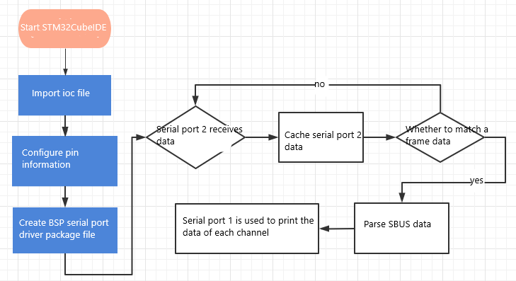
6.4. Core code explanation
- Add the following contents in bsp_uart.c:
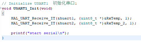
USART1_Init():Initialize serial port related contents, turn on serial port 1 and serial port 2 to receive 1 data.
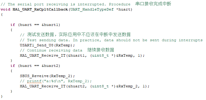
- In the serial port interrupt callback to determine whether the serial port 2 data received, while distinguishing between serial port 1 or serial port 2 which received data.
- New bsp_sbus.h and bsp_sbus.c files to manage the content of the sbus data parsing. In bsp_sbus.h create the following new content:
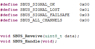
SBUS_ALL_CHANNELS controls the number of channels to be parsed. By default, only eight channels are displayed, and if you need to display all the channels, then change it to 1.
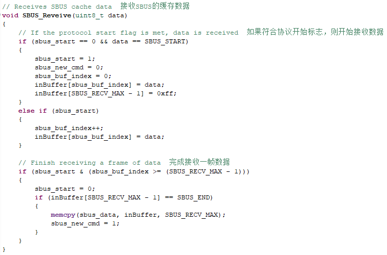
- SBUS_Reveive(data) receives the data from the serial port as a cache, and if it conforms to the communication protocol of SBUS, it updates a frame of data to the sbus_data array.
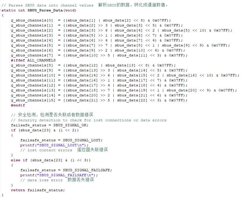
- Parse the data in sbus_data according to the SBUS communication protocol.
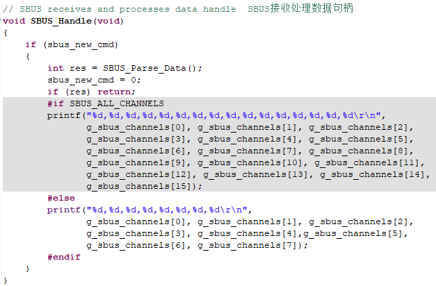
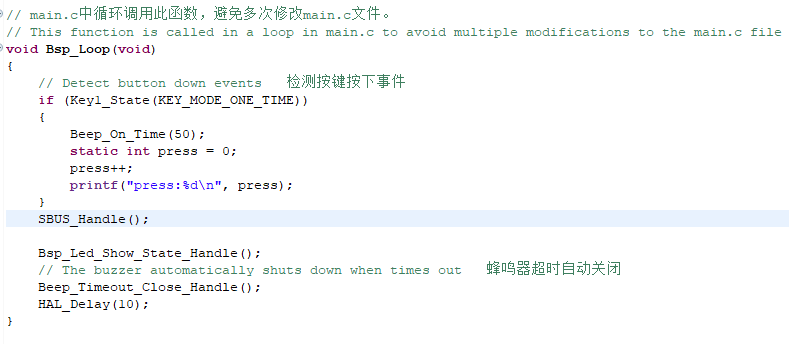
- The SBUS_Handle() function is called cyclically in Bsp_Loop() to print out the parsed data of each channel through serial port 1.
6.5 Hardware Connection
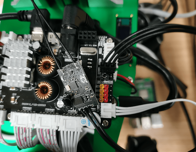
Since SBUS communication needs to connect the SBUS receiver to the SBUS interface on the expansion board, S connects to signal, V connects to power positive, and G connects to ground. So you need to prepare your own modeling remote control and SBUS receiver, pair them in advance and turn on the power switch.
6.6 Experimental effect
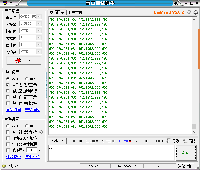
After burning the program, the LED light flashes every 200 milliseconds, connect the expansion board to the computer via micro-USB cable and open the serial assistant (specific parameters are shown in the following figure), you can see that the serial assistant has been printing the data of the various channels of the air model remote control, and when we manually toggle the rocker or buttons of the air model remote control, the data will follow the changes.