Welcome to Transbot SE repository
3.1About expansion board and update firmware
About expansion board and update firmware
About expansion board and update firmware1、Transbot SE expansion board1.1、Schematic diagram of component distribution1.2、FAQ
1、Transbot SE expansion board
1.1、Schematic diagram of component distribution
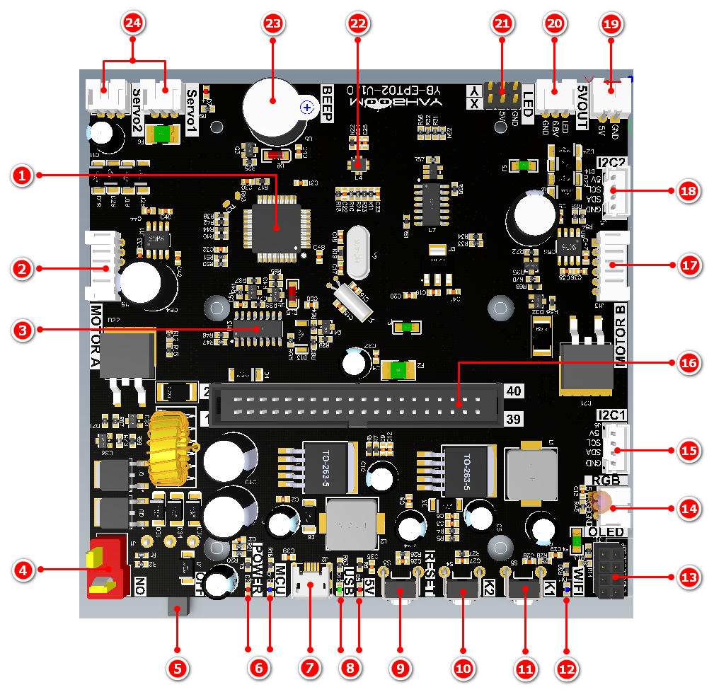
① On-board single-chip microcomputer: In order to simplify the development steps, the Transbot SE expansion board integrates a which mainly manages the component drivers on the expansion board. The driving content includes: robotic arm, active buzzer, six-axis attitude sensor, PWM servo pan/tilt , motor, button K2. The single-chip microcomputer and Jetson Nano board communicate through the serial port。When the single-chip microcomputer will respond to the serial port information. The specific communication protocol can be viewed in [Transbot SE baseboard and main control board communication protocol].
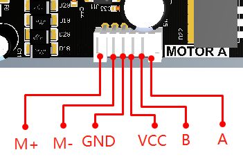
② Motor interface A: Connect to the Transbot SE motor of left wheel. The interface line sequence is shown in the figure:
③ Serial communication chip: onboard CH340C serial chip.
④ DC 12V power supply T-type interface: be used to connect battery pack.
⑤Power switch: ON/OFF.
⑥Indicator light: MCU indicator light indicates whether the MCU on the expansion board is working normally. Normally working status: fast flashing twice every 3 seconds, abnormally working status: always on or off. Power indicator indicates whether the expansion board is normally powered.
⑦Micro USB interface: connect to the computer USB port, it cab be used update the firmware of the expansion board.
⑧Indicator light: When the 5V indicator light is on, it means that the 5V voltage supply of the board is normal. If the USB indicator flashes, it means there is data coming in from the Micro USB port.
⑨RESET button:It can restart the MCU on the expansion board.
⑩K2 key: The buzzer will sound once every time the K2 key is pressed, and the special effect of the RGB colorful light bar will be switched. K2 key is only connected to the MCU in the expansion board. The function of this button has been fixed and cannot be customized by yourself.
⑪K1 key: By default, after the Transbot SE system and APP control process is started, long press the button K1 to enter the network distribution mode, and the robot car can connect to the network by scanning the QR code.When the APP control process is closed, the function of this button can be customized by yourself. K1 is connected to the physical pin 11 of Jetson NANO(BCM number is 17).
⑫WiFi indicator: By default, after the Transbot SE system and APP control process is started, when robot car connect WiFi, this light will keep on.
When the APP control process is closed, the function of this light can be customized by yourself. It is connected to the physical pin 12 of Jetson NANO(BCM number is 18).
⑬OLED interface: IIC communication, I2C interface 1 and interface 2 are connected in parallel. It is connected to the physical pin 3, 5 of Jetson NANO.
⑭Colorful light bar interface: Transbot SE didn't support that.
⑮IIC interface1: It is connected to the physical pin 3, 5 of Jetson NANO.
⑯Flat cable socket: The expansion board is connected with the main control board through the flat cable, communicates with the main control board and supplies power to it.
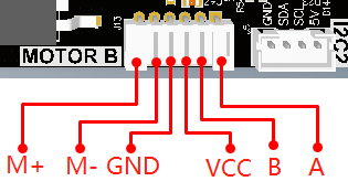
⑰Motor interface B: Connect to the Transbot motor of right wheel. The interface line sequence is shown below.
⑱IIC interface2: It is connected to the physical pin 3, 5 of Jetson NANO.
⑲DC 5V power output: 5V DC voltage can be output, rated current: 0.5 A.
⑳OLED searchlight interface: Transbot SE didn't support that.
㉑PWM servo interface: Two PWM servos can be connected, the yellow is the signal line, the red is 5V, and the black line is GND.
㉒Six-axis attitude sensor: Provides the current pose information of Transbot SE to Jetson NANO.
㉓Active buzzer: When receiving a high-level signal, the whistle will sound.
㉔Robotic arm interface: Servo1 and Servo2 are connected in parallel, robotic arm can be connected to any one of them, rated current: 2.6 A.
1.2、FAQ
1: How does main control board communicate with the expansion board?
A: Main control board sends data through the serial port, and then transmits the data to the MCU on the expansion board through the 40 Pin cable. The MCU automatically receives and parses the serial data.
2: When using the Transbot SE, does the main control board need additional power supply?
A: Transbot SE kit include a battery pack insert the battery pack into the DC 12V power T-type interface of the expansion board. Open the power switch, the expansion board integrates a voltage conversion chip will provides DC 5V power, and transmits it to main control board through a 40 Pin cable. So main control board does not need an additional separate power supply.
3: Which functions on the Transbot SE are managed by the MCU on expansion board? Which functions are directly managed by main control board?
A: The parts managed by main control board: K1, WiFi indicator, l2C interface, OLED interface.
The part managed by MCU on the expansion board: robotic arm, active buzzer, six-axis attitude sensor, PWM servo, K2, RESET button, etc.
4: Why does the buzzer whistle once every second when Transbot SE hits the wall and causes the motor to stall?
A: The above situation means that the motor still outputs torque when the speed is 0 rpm.
At this time, a large current will be generated on the expansion board. If there is no protection circuit, it may cause the motor to burn out.
Therefore, we have designed a motor protection circuit on the Transbot SE expansion board. When the motor stall current is too large, the protection circuit will sound a whistle and automatically disconnect the power supply of the motor. When the power supply is restored after 1 second, the system will again determine whether the current motor status is normal, if motor still stall, it will automatically disconnect for another 1s.
5: Insert a USB data cable into the Transbot SE expansion board, use a serial port assistant to open the serial port of the Transbot SE, and press the RESET reset button on the expansion board. Why is the microcontroller not working?
A: The expansion board is equipped with an automatic download circuit for the microcontroller. If the expansion board is connected through a serial assistant and the reset button is pressed,the microcontroller will first enter the writing mode instead of the normal working mode. At this point, you need to do is turn off the serial assistant or unplug the USB data cable, press the reset button, and then connect again.
6: How to update the microcontroller firmware for an expansion board? Why do I need to update the firmware? A: The microcontroller integrated with the Transbot SE expansion board has already written the firmware before leaving the factory. If not necessary, please do not need to update the firmware. If you need to update the firmware, please refer to updating firmware tutorials or d nical support.
7.What is the username and password for the factory image ofTransbot SE?
A: Jetson Nano version:
User name is Jetson, password is yahboom.
Raspberry Pi 4B version:
User name is pi, password is yahroom
Log in password for JupyterLab is yahboom