Welcome to Transbot SE repository
4.MoveIt kinematics design
4. MoveIt kinematics design
4. MoveIt kinematics design4.1. Pose description of 3D space4.2. Start4.3. Reverse solution key code4.3.1.python code4.3.2.C++code4.4. Positive solution key code4.4.1.python code4.4.2.C++code4.5. MoveIT kinematics plugin
This lesson takes the MoveIT simulation as an example. If you need to set the synchronization between the real machine and the simulation, please refer to the lesson [02, MoveIt Precautions and Controlling the Real Machine]. ! ! ! be careful! ! !
The effect demonstration is a virtual machine, and other masters are running (related to the performance of the master, depending on the actual situation).
4.1. Pose description of 3D space
First, a coordinate system is specified, relative to the coordinate system, the position of the point can be represented by a 3-dimensional column vector; the orientation of the rigid body can be represented by a 3×3 rotation matrix. The 4×4 homogeneous transformation matrix can unify the description of the rigid body position and attitude (pose), which has the following advantages:
(1) It can describe the pose of the rigid body and the relative pose (description) of the coordinate system.
(2) It can represent the transformation (mapping) of a point from the description of one coordinate system to the description of another coordinate system.
(3) It can represent the transformation (operator) of the pose description before and after the rigid body motion.
- Location description - Location vector
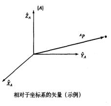
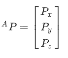
A coordinate system {A} is represented by three mutually orthogonal unit vectors with arrows. Then the representation of the spatial position of point p in the coordinate system {A} is:
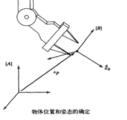
- Description of the orientation - rotation matrix
The commonly used rotation transformation matrix is to rotate an angle around the X axis, around the Y axis or around the Z axis. they are respectively:

- Inhomogeneous representation
After the vector a has undergone a rotation R and a translation t,get $a' : a'=R*a+t$
- Homogeneous representation

The universal rotation matrix R is:
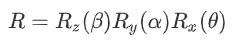
The rotation matrix rotation process here is to rotate the angle θ around the X axis first, then rotate the angle α around the Y axis, and finally rotate the angle β around the Z axis.
- Right-hand rule
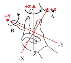
The thumb points to X, the index finger to Y, and the middle finger to Z.
- RPY and Euler Angles
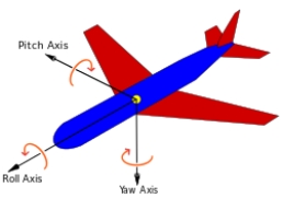
According to the rotation order of its own coordinate system, it is Z-->Y-->X, which is called eulerYPR (Yaw Pitch Roll);
According to the rotation order of the external coordinate system (reference coordinate system) is x-->y-->z,which is called RPY (Roll Pitch Yaw);
When describing the same pose, the above two representations are equivalent, that is, the angle value of the Yaw Pitch Roll is the same.
Definition: Yaw yaw angle ϒ ; Pitch angle β ; Roll angle α
- Quaternion method
The approximate definition is that a vector is represented by a scalar and three imaginary axes, called a quaternion. [x, y, z, w] The range of each data is [-1,1].
4.2. Start
Positive solution: In a robotic arm,knowing each joint angle, solve for the end pose.
Inverse solution: In a robotic arm,knowing the pose of the end (except the gripper), find the angle of each joint.
Start the MoveIT
roslaunch transbot_se_moveit_config demo.launch Start the inverse solution node (choose one of two)
xxxxxxxxxxrosrun transbot_se_moveit_config 02_set_pose_plan # C++rosrun transbot_se_moveit_config 02_set_pose_plan.py # pythonStart the positive solution node (choose one of two)
xxxxxxxxxxrosrun transbot_se_moveit_config 03_set_joint_plan # C++rosrun transbot_se_moveit_config 03_set_joint_plan.py # python4.3. Reverse solution key code
Note: Due to the limited range of the robotic arm, it may not be able to reach the specified target pose. This is a normal situation, and multiple executions of the cycle can only slightly increase the planning success rate. Not only the position, but also the posture of the end must be considered. We can view the poses of each link through rviz, as shown below,
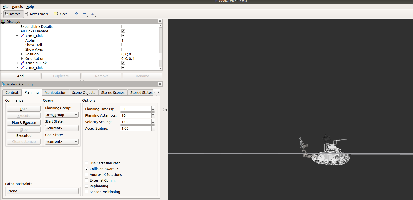
The [Position] and [Orientation] in [arm1_link] in the above figure are the end poses. When using the inverse solution, you can also directly set the position and attitude quaternion of the target point.
4.3.1.python code
Set target pose
xxxxxxxxxx # Create the pose instance pos = PoseStamped() # Set location pos.pose.position.x = 0.00054 pos.pose.position.y = 0.13143 pos.pose.position.z = 0.04868 # Set pose pos.pose.orientation.x = 0.44672 pos.pose.orientation.y = -0.44672 pos.pose.orientation.z = 0.54812 pos.pose.orientation.w = 0.54812Set target point
xxxxxxxxxx # Set target point transbot.set_pose_target(pos)Loop execution path planning
xxxxxxxxxx # Execute multiple times to improve the success rate for i in range(5): # Exercise planning plan = transbot.plan() if len(plan.joint_trajectory.points) != 0: print ("plan success") # Run after planning is successful transbot.execute(plan) break else: print ("plan error")4.3.2.C++code
Set target pose
xxxxxxxxxx //Set specific location geometry_msgs::Pose pose; pose.position.x = 0.000549; pose.position.y = 0.161208; pose.position.z = 0.038591; //Set target pose pose.orientation.x =0.449019; pose.orientation.y =-0.449019; pose.orientation.z =0.5462434; pose.orientation.w =0.5462434; transbot.setPoseTarget(pose);Loop execution path planning
xxxxxxxxxx int index = 0; // Execute multiple times to improve the success rate while (index <= 10) { moveit::planning_interface::MoveGroupInterface::Plan plan; // Exercise planning const moveit::planning_interface::MoveItErrorCode &code = transbot.plan(plan); if (code == code.SUCCESS) { ROS_INFO_STREAM("plan success"); yahboomcar.execute(plan); break; } else { ROS_INFO_STREAM("plan error"); } index++; }4.4. Positive solution key code
4.4.1.python code
Set target point
xxxxxxxxxxjoints = [0.49, 0.93]transbot.set_joint_value_target(joints)Loop execution path planning
xxxxxxxxxx #Execute multiple times to improve the success rate for i in range(5): #Exercise planning plan = transbot.plan() if len(plan.joint_trajectory.points) != 0: print ("plan success") #Run after planning is successful transbot.execute(plan) break else: print ("plan error")4.4.2.C++code
Set target point
xxxxxxxxxx //Set specific location vector<double> pose{0.79, 3.14}; transbot.setJointValueTarget(pose);Loop execution path planning
xxxxxxxxxx moveit::planning_interface::MoveGroupInterface::Plan plan; const moveit::planning_interface::MoveItErrorCode &code = transbot.plan(plan); if (code == code.SUCCESS) { ROS_INFO_STREAM("plan success"); //Show track string frame = transbot.getPlanningFrame(); moveit_visual_tools::MoveItVisualTools tool(frame); tool.deleteAllMarkers(); tool.publishTrajectoryLine(plan.trajectory_, transbot.getCurrentState()->getJointModelGroup("arm_group")); tool.trigger(); transbot.execute(plan); } else { ROS_INFO_STREAM("plan error"); }4.5. MoveIT kinematics plugin
The MoveIT kinematics plugin is the file [kinematics.yaml]
If you need to replace or modify, you can directly modify the file[kinematics.yaml]
xxxxxxxxxxroscd transbot_se_moveit_config/config/sudo vim kinematics.yaml
- kdl
xxxxxxxxxxarm_group:kinematics_solver: kdl_kinematics_plugin/KDLKinematicsPluginkinematics_solver_search_resolution: 0.005kinematics_solver_timeout: 0.005
- trac_ik
xxxxxxxxxxarm_group:kinematics_solver: trac_ik_kinematics_plugin/TRAC_IKKinematicsPluginkinematics_solver_search_resolution: 0.005kinematics_solver_timeout: 0.005