Welcome to ROSMASTER M3 repository
04.Robot state estimation
Robot State Estimation
Robot State Estimation1. Course Content2. Preparations2.1 Content Description2.2 Start the Agent3. Run the Example3.1 Start the Program3.2 View Fused Odometry Data4. Source Code Explanation5. Fused Odometry Parameters
1. Course Content
Basic: After the program runs, it combines the IMU data read from the ROS expansion board for multi-sensor fusion to obtain fused odometry data.
Advanced: Understand the meaning of robot_localization parameters and the principle of odometry fusion.
2. Preparations
2.1 Content Description
This lesson uses the Jetson Orin NX as an example. For Raspberry Pi boards, you need to open a terminal on the host machine, enter the command to get into the Docker container, and then input the commands mentioned in this lesson in the terminal within the Docker container. A tutorial on how to enter the Docker container from the host can be found in this product's guide [00.Configuration and Operation Guide]-[3.Enter the Docker (For RPI5)]. For ORIN and RDK boards, you can directly open a terminal and enter the commands mentioned in this lesson.
2.2 Start the Agent
Note: If it is already running, you do not need to start it again.
Enter the command in the vehicle's terminal:
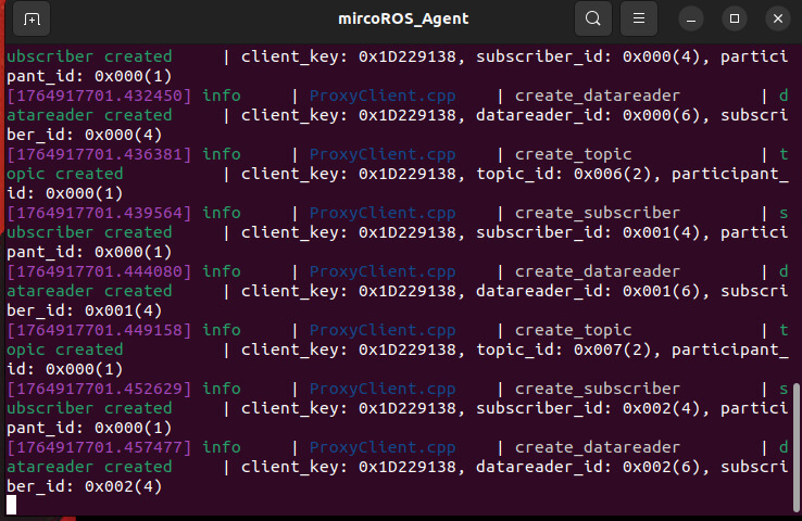
start_agentThe terminal will print the following information, indicating a successful connection:
3. Run the Example
3.1 Start the Program
For Raspberry Pi 5 users, if the ROS container is not started, you need to start it first,
xxxxxxxxxxbringup_m3
Open a terminal inside the container,
xxxxxxxxxxexec_m3
Enter the command,
xxxxxxxxxxros2 launch m3_bringup car_base.launch.py
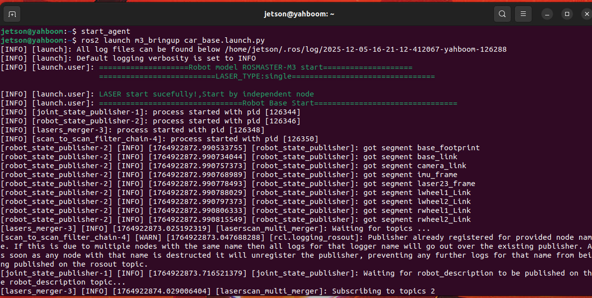
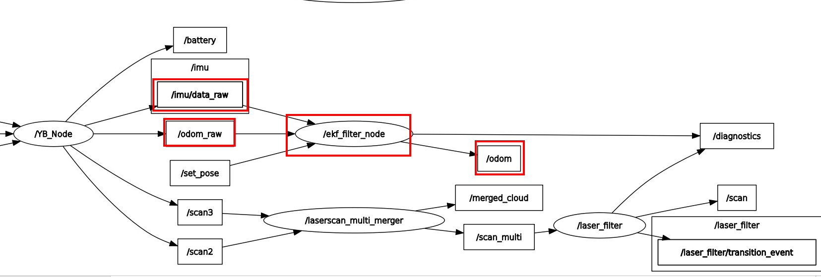
- There is no visual display here, you can check the relationship between nodes and the published topics in rqt_graph.
xxxxxxxxxxros2 run rqt_graph rqt_graph
The
ekf_filter_nodenode receivesodom_rawdata andimu/data_rawdata for fusion, and finally outputs and publishesodomodometry data, where:/odom_rawis the wheel odometry data calculated by the chassis's STM32, which collects encoder data from each wheel motor and computes it using the forward kinematics of the Mecanum wheel chassis./imu/data_rawis the data published by the chassis's STM32 after collecting IMU data.- The
ekf_filter_nodenode is one of the nodes in therobot_localizationpackage and can fuse an arbitrary number of sensors. The node has no limit on the number of input sources.
[!TIP]
- In robotics, odometry is also known as local positioning. Common types of odometry include wheel, laser, visual, and inertial odometry. The ROSMASTER-M3 chassis uses wheel odometry.
3.2 View Fused Odometry Data
- Enter the command in the terminal:
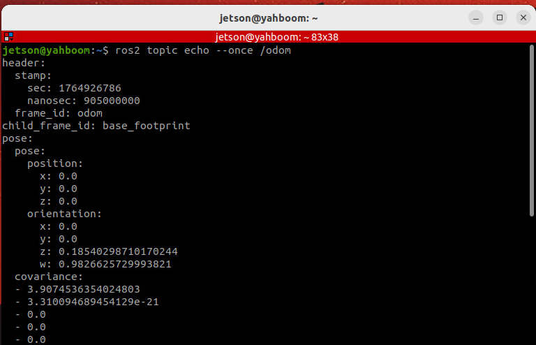
xxxxxxxxxxros2 topic echo --once /odom
header: Describes the data frame information.pose: Describes the robot's pose information, consisting of position and orientation information.covariance: Describes the covariance matrix of the data.
4. Source Code Explanation
car_base.launch.pypath: Starts the laser fusion and fused odometry localization node.
xxxxxxxxxx~/yahboomM3_ws/user_ws/src/m3_bringup/launch/common/car_base.launch.py
- This launch file mainly starts the laser fusion node and the fused odometry node, and prints the startup log.
xdef generate_launch_description(): # Laser radar fusion and filtering startup file bringup_laser_launch=IncludeLaunchDescription(PathJoinSubstitution([FindPackageShare('m3_bringup'),'launch','common', 'bringup_laser.launch.py'])) # Multi-odometry fusion positioning startup file merge_odom_launch=IncludeLaunchDescription(PathJoinSubstitution([FindPackageShare('m3_bringup'),'launch', 'common','merge_odom.launch.py'])) return LaunchDescription([ bringup_laser_launch, # Laser radar fusion and filtering startup file TimerAction( period=2.0, actions=[ merge_odom_launch, ] ), LogInfo(msg=[Fore.GREEN+'================================Robot Base Start================================',Fore.RESET]), ])
merge_odom.launch.pypath: Starts the fused odometry localization node.
xxxxxxxxxx~/yahboomM3_ws/user_ws/src/m3_bringup/launch/common/merge_odom.launch.py
- This launch file starts the
ekf_filter_nodefrom therobot_localizationpackage for multi-sensor fusion localization and finally prints the startup log.
xxxxxxxxxxdef generate_launch_description()->LaunchDescription: localization_config_file=os.path.join(get_package_share_directory('m3_bringup'), 'config', 'robot_localization.yaml') # Declare arguments declared_arguments = [] declared_arguments.append( DeclareLaunchArgument( "namespace", default_value="", description="Add namespace", ) ) # Initialize Arguments namespace=LaunchConfiguration("namespace") return LaunchDescription([ *declared_arguments, LogInfo( msg=[Fore.GREEN+'====================Merge_Odom Localization Start====================\n',Fore.RESET]), Node( package='robot_localization', executable='ekf_node', name='ekf_filter_node', namespace=namespace, output='screen', parameters=[localization_config_file], remappings=[('/odometry/filtered','/odom')] ),])
5. Fused Odometry Parameters
Parameter file path:
xxxxxxxxxx~/yahboomM3_ws/user_ws/src/m3_bringup/config/robot_localization.yaml
- Here, the sensor fusion uses the wheel odometry and IMU angular velocity for fusion. See the comments for the specific meaning of the parameters.
xxxxxxxxxx### ekf config file# ###ekf_filter_node ros__parameters use_sim_timefalse frequency25.0 # Fused odometry output frequency sensor_timeout0.3 # Sensor timeout, the minimum frequency at which the filter generates new output, determined by the sensor frequency two_d_modetrue # 2D position state estimation, false enables 3D state estimation transform_time_offset0.0 # Time offset provided by the ekf_localization_node for generated transforms transform_timeout0.0 # Specifies the TF listener timeout print_diagnosticsfalse # Output debugging information debugfalse # Output debugging information to a file print_diagnosticsfalse # Output log to diagnostics topic, only enable for debugging debug_out_file/path/to/debug/file.txt # Debug file output path, only effective when debug is true publish_tftrue # Whether to publish TF transforms permit_corrected_publicationfalse # Whether to allow old sensor data to trigger a state update and then republish the result publish_accelerationfalse # Whether to publish the acceleration state (accel field in nav_msgs/Odometry) map_framemap # Defaults to "map" if unspecified odom_frameodom # Defaults to "odom" if unspecified base_link_framebase_footprint # Robot's base coordinate frame (fixed to the robot) world_frameodom # The filter's world coordinate frame, used to define the reference frame for state estimation # Wheel odometry (provided by the chassis wheel motor encoders), frequency is about 11hz odom0odom_raw # Test 1 odom0_configfalse false false false false false true true false false false true false false false odom0_queue_size5 # Queue size for subscribing to the odom0 topic odom0_nodelayfalse odom0_differentialfalse # Whether to convert absolute pose data to relative velocity (via differential calculation) for fusion. odom0_relativetrue # Whether to use the sensor's first data as the "zero point", with subsequent data participating in fusion as relative values. odom0_pose_use_child_framefalse # Whether to use the initial pose of the child_frame_id in the sensor message as the origin, suitable for scenarios where the sensor has a fixed offset from base_link # odom0_pose_rejection_threshold: 20.0 # Mahalanobis distance threshold for pose data, values exceeding this are considered outliers and ignored. # odom0_twist_rejection_threshold: 1.5 # Mahalanobis distance threshold for twist (velocity) data. # IMU data, raw data provided by the chassis ROS control board, filtered data is published, frequency is about 25hz imu0imu/data_raw # Test 1 (works well, yaw angle is stable during continuous rotation, will try to debug and calibrate IMU separately later) imu0_configfalse false false false false false false false false false false true false false false imu0_nodelayfalse imu0_differentialfalse imu0_relativefalse imu0_queue_size5 # imu0_pose_rejection_threshold: 20.0 # Note the difference in parameter names # 0.8 # imu0_twist_rejection_threshold: 1.542 # 0.8 # imu0_linear_acceleration_rejection_threshold: 10.0 # imu0_remove_gravitational_accelerationtrue # Whether to remove the gravitational component from the IMU's acceleration data. Enable if the IMU does not automatically remove gravity. # Predict based on control commands use_controlfalse # Whether to use control input (e.g., cmd_vel) in the prediction phase to generate an acceleration term to assist state prediction. stamped_controlfalse # Specifies the message type of the control input. true for geometry_msgs/TwistStamped (with timestamp), false for geometry_msgs/Twist (without timestamp). control_timeout0.2 # Timeout for control commands (in seconds). If no new command is received within this duration, the filter will stop using control input for prediction. control_configtrue false false false false true # Specifies which velocity dimensions use control input, in the order: [vx, vy, vz, vroll, vpitch, vyaw]. true enables control input for that dimension. acceleration_limits1.5 0.0 0.0 0.0 0.0 3.4 # Maximum acceleration limits for each velocity dimension (in units of velocity/second, e.g., m/s² or rad/s²). deceleration_limits1.5 0.0 0.0 0.0 0.0 4.5 # Maximum deceleration limits for each velocity dimension (maximum rate of change opposite to the direction of acceleration). deceleration_gains0.9 0.9 0.0 0.0 0.0 1.0 # Smoothing factor for acceleration/deceleration (between 0 and 1), used to simulate the robot's inability to instantly reach maximum acceleration/deceleration (e.g., due to inertia). # The closer the value is to 1, the closer the acceleration/deceleration is to the set limit. The closer the value is to 0, the smoother the change (and the greater the delay).#==========================================================================================================================================================# Sensor covariance. It is recommended to use the default values without professional measurement equipment for calibration.##========================================================================================================================================================== # Defines the process noise covariance matrix (15x15) for the filter's prediction model. The larger the value, the lower the filter's confidence in the prediction, and the more it relies on sensor data. process_noise_covariance # The covariance matrix for the initial state estimate (15x15). The larger the value, the lower the confidence in the initial state. initial_estimate_covariance