yahboom
HomeLearn
Solution
Blog
Online Store
About Us
EN/中文
ROSMASTER M3📖
00.Configuration and Operation Guide
  • 1.Quick start handle to control the car
  • 2.Log in to the car and view the code
  • 3.Enter the Docker (For RPI5)
  • 4.Camera and Radar Configuration (Must Read)
  • 5.Assembly video
  • 6.Modify Control Board Firmware Parameters
01.Chassis Control Course
  • 01.ROS control
  • 02.Handle control
  • 03.Keyboard control
  • 04.Robot state estimation
  • 05.Data remote visualization
  • 06.Line velocity calibration
  • 07.Angular velocity calibration
  • 08.Robot URDF model
  • 09.Line patrol automatic driving
  • 10.Patrol
02.Lidar Course
  • 01.Lidar introduction and use
  • 02.Lidar point cloud fusion and filtering
  • 03.Lidar obstacle avoidance
  • 04.Lidar tracking
  • 05.Lidar guard
  • 06.Gmapping-SLAM mapping
  • 07.Cartographer-SLAM mapping
  • 08.slam_toolbox mapping
  • 09.Lifelong mapping
  • 10.Navigation2 single-point navigation avoid
  • 11.Navigation2 multi-point navigation avoid
  • 12.Cartographer relocalization navigation
  • 13.slam_toolbox localization and navigation
  • 14.Synchronous mapping and navigation
  • 15.RTAB-Map mapping
  • 16.RTAB-Map navigation
  • 17.APP mapping and navigation
03.AI Model Basics
  • 1.AI large model types and principles
  • 2.RAG retrieval enhancement and model training samples
  • 3.Embodied intelligent robot system architecture
  • 4.Embodied intelligent functions core source code
04.AI Model Development
  • 01.Register a model service provider account
  • 02.Configuring API-KEY
  • 03.Introduction to Dify
  • 04.Basic Dify Features
  • 05.AI Large Model Development - chatbot
  • 06.Deploy the RAG knowledge base
  • 07.RAG knowledge base + chatbot
  • 08.AI agent workflow
  • 09.Custom wake-up response
  • 10.Core module testing tools
05.AI Model - Voice Version
  • 1.Semantic understand and command follow
  • 2.Multimodal visual understanding
  • 3.Multimodal visual understanding+SLAM navigation
  • 4.Intention estimation
06.AI Model - Text Version
  • 1.Semantic understand and command follow
  • 2.Multimodal visual understanding
  • 3.Multimodal visual understanding+SLAM navigation
  • 4.Intention estimation
07.Road Network Planning and Navigation
  • 1.Introduction and Quick Start
  • 2.Constructing a Pose Map
  • 3.Road Network Labelling
  • 4.Inter-Road Network Planning and Navigation
  • 5.Free-Pose Road Network Navigation
  • 6.Path Replanning
08.Autonomous Driving expand(Need purchase track map)
  • 01.Environment Setup & Precautions
  • 02.YOLO Environment Configuration
  • 03.Data Collection
  • 04.Data Annotation
  • 05.YOLOv11 Model Training
  • 06.Model Format Conversion
  • 07.Vehicle Centerline Calibration
  • 08.Lane Detection
  • 09.Lane-Keeping Autonomous Driving
  • 10.Traffic Sign Recognition
  • 11.Comprehensive Autonomous Driving Applications
  • 12.Autonomous Driving Debugging Module
  • 13.Road Network Planning with Track Map
  • 14.Road Network Planning with Traffic Sign Recognition
  • 15.AI Model with Road Network Planning
  • 16.AI Model with Track Map and SLAM Navigation
  • 17.AI Model with Road Network Planning and Autonomous Driving
09.Depth Camera Course
  • 01.Dabai_DCW2 Camera Introduction
  • 02.Nuwa-HP60C Camera Introduction
  • 03.Depth Pseudo-Color Image
  • 04.Depth Camera Distance Measurement
  • 05.Wood Block Volume Measurement
  • 06.Edge Detection
  • 07.YOLOv11 Object Detection
  • 08.YOLOv11 Object Tracking
  • 09.Color Following
  • 10.Face Following
  • 11.QR Code Following
  • 12.Machine Code Following
  • 13.KCF Object Tracking
  • 14.QR Code Motion Control
  • 15.AR Vision
10.Mediapipe Visual Course
  • 01.Hand Detection
  • 02.Posture Detection
  • 03.Overall Detection
  • 04.Facial Landmark Detection
  • 05.3D Object Recognition
  • 06.Face Detection
  • 07.Gesture Recognition
  • 08.Face Special Effects
  • 09.Brush
  • 10.Finger Control
  • 11.Palm Target Positioning
  • 12.Fingertip Trajectory Recognition
  • 13.Gesture Following
  • 14.Posture Following
  • 15.Gesture Motion Control
11.Multi-vehicle Course
  • 1.Multi-vehicle Control
  • 2.Multi-vehicle Navigation
  • 3.Multi-vehicle Platoon
12.AI Large Model Basic Course
Offline large model (Text Interaction)
  • 0. AI Large Model Mirroring Explanation
  • 1. Deployment of large-scale AI models
  • 2. Installation of the large model dialogue platform
  • 3. Meta AI Llama 3.2 model
  • 4. Alibaba Cloud Qwen3 Model
  • 5. DeepSeek DeepSeek-R1 model
  • 6. Microsoft Phi-4 mini model
  • 7. Alibaba Cloud Qwen2.5vl Visual Multimodal Large Model
  • 8. Google Gemma3 Visual Multimodal Large Model
  • 9. Llava Visual Multimodal Large Model
  • 10. Multimodal Visual Understanding Applications
  • 11.MiniCPM-V Visual Multimodal Large Model
  • 12. Multimodal Text-Based Image Application
  • 13. Multimodal Video Analysis Application
  • 14. Multimodal table scanning application
  • 15. Multimodal visual positioning applications
  • 16. Multimodal Autonomous Agent Application
Offline large model (Voice Interaction)
  • 0. Voice Interaction Hardware Connection (Must Read)
  • 1. Offline speech-to-text (ASR)
  • 2. Offline Text-to-Speech (TTS)
  • 3. AI large model voice interaction
  • 4. Multimodal visual understanding and voice interaction
  • 5. Multimodal Text-Based Image Application
  • 6. Multimodal Video Analysis Application
  • 7. Multimodal visual positioning applications
  • 8. Multimodal table scanning application
  • 9. Multimodal Autonomous Agent Applications
  • 10. AI large model offline voice assistant
Online large model (Text Interaction)
  • 1. OpenRouter Large Model API Aggregation Platform
  • 2. Multimodal visual understanding applications
  • 3. Multimodal visual positioning applications
  • 4. Multimodal table scanning application
  • 5. Multimodal Autonomous Agent Applications
Online large model (Voice Interaction)
  • 0. Voice Interaction Hardware Connection (Must Read)
  • 1. Online speech-to-text (ASR)
  • 2. Online Text-to-Speech (TTS)
  • 3. AI large model voice interaction
  • 4. Multimodal visual and voice interaction
  • 5. Multimodal visual positioning applications
  • 6. Multimodal table scanning application
  • 7. Multimodal Autonomous Agent Applications
  • 8. AI large model online voice assistant
13.Control Board Course
1.Development environment setup
  • 1.Introduction to the Control Board
  • 2.Set up the STM32CUBEIDE development environment
  • 3.Burning STM32 firmware using SWD
  • 4.Burning STM32 firmware using serial port
  • 5.Compile the microros driver library
  • 6.Install and start the microros agent
  • 7.Import Project
2.Control board STM32 basic routine
  • 1.Turn on the LED light
  • 2.Button functions
  • 3.Drive the buzzer
  • 4.Serial communication
  • 5.Battery voltage detection
  • 6.Driving PWM Servo
  • 7.Drive motor
  • 8.Read motor encoder data
  • 9.PID control of motor speed
  • 10.Robot kinematics analysis theory
  • 11.Read IMU data
  • 12.Read Lidar data
  • 13.Flash access data
  • 14.Driving OLED Displays
  • 15.Driving RGB light strip
  • 16.SBUS model aircraft remote control
  • 17.USB controller remote control
  • 18.CAN bus communication
3.Control board micro_ros basic routine
  • 1.Post a topic
  • 2.Subscribe to a topic
  • 3.Multi-topic subscription and publishing
  • 4.Subscribe to the buzzer topic
  • 5.Subscribe to the bus servo topic
  • 6.Subscribe to the rate control topic
  • 7.Release Speed Topic
  • 8.Publish IMU data topic
  • 9.Publish radar data topic
14.Main Control Course
Jetson Orin Nano_NX
  • 1.Jetson Orin board introduction
  • 2.Restore the factory image system
  • 3.Backup SSD system
  • 4.SSD expansion
  • 5.Network configuration
  • 6.SSH remote login
  • 7.VNC remote control
  • 8.Remote file transfer
  • 9.Jtop tool
  • 10.Exchange space expansion
Raspberry Pi
  • 1. Introduction to Raspberry PI 5
  • 2. Raspberry PI system installation and backup
  • 3. Powering the Raspberry PI 5
  • 4. Startup of Raspberry PI 5
  • 5. Update and upgrade operating system
  • 6. Introduction to raspi-config tool
  • 7. config.txt file description
  • 8. Network Configuration
  • 9. remote access
  • 10. Transfer files remotely
  • 11. Set display resolution and rotation
  • 12. Set screen to sleep
  • 13. Play audio and video
  • 14. Using USB camera
  • 15. Using MIPI camera
  • 16. Get real-time temperature of Raspberry Pi
RDKX5
  • 1.Introduction to RDK X5 board
  • 2.Write system file
  • 3.Hardware interface description
  • 4.Install case and other accessories
  • 5.Network configuration
  • 6.Remote login
  • 7.Update system
  • 8.srpi-config user guide
  • 9.config. txt configuration file
  • 10.Self-startup setting
  • 11.RDK exclusive command usage
  • 12.Linux command usage
  • 13.GPIO readwrite operation
  • 14.Image classification algorithm
  • 15.Use USB camera
  • 16.Use MIPI camera
  • 17.Binocular camera depth algorithm
15.YOLOv11 Development (ORIN)
  • 1.YOLO environment construction
  • 2.CLI use
  • 3.Object detection
  • 4.Instance segmentation
  • 5.Pose estimation
  • 6.Image classification
  • 7.Oriented object detection
  • 8.Model conversion
  • 9.Dataset annotation
  • 10.Model Training_Conversion
  • 11.Model prediction
16.YOLOv11 Development(RDKX5)
  • 1.YOLO environment construction
  • 2.CLI use
  • 3.Object detection
  • 4.Instance segmentation
  • 5.Pose estimation
  • 6.Image classification
  • 7.Oriented object detection
  • 8.Model prediction
  • 9.Model Quantization
17.YOLOv11 Development (RPI)
  • 1.YOLO environment construction
  • 2.CLI use
  • 3.Object detection
  • 4.Instance segmentation
  • 5.Pose estimation
  • 6.Image classification
  • 7.Oriented object detection
  • 8.Model conversion
  • 9.Model prediction
18.Linux Operating System
  • 1.Introduction to Linux system
  • 2.Ubuntu file system
  • 3.Ubuntu common commands
  • 4.Ubuntu common editors
  • 5.Ubuntu software operation commands
  • 6.Virtual machine installation
  • 7.SSH remote control
  • 8.VNC remote control
  • 9.Transfer files remotely
  • 10.Driver library and communication
  • 11.Static IP and hotspot mode
  • 12.Bind device ID
  • 13.Capacity expansion and resource allocation
  • 14.Update system software sources
  • 15.Set root user password
  • 16.sudo free password
  • 17.Connect to WiFi network
  • 18.View system version
  • 19.Customized service management
  • 20.Back up system image
19.ROS2 Basic Course
  • 1.Introduction to ROS2
  • 2.ROS2 install Humble
  • 3.ROS2 development environment
  • 4.ROS2 workspace
  • 5.ROS2 function package
  • 6.ROS2 node
  • 7.ROS2 topic communication
  • 8.ROS2 service communication
  • 9.ROS2 action communication
  • 10.ROS2 custom interface message
  • 11.ROS2 parameter service case
  • 12.ROS2 meta-function package
  • 13.ROS2 distributed communication
  • 14.ROS2 DDS
  • 15.ROS2 time related API
  • 16.ROS2 common command tools
  • 17.ROS2 rviz2 use
  • 18.ROS2 rqt toolbox
  • 19.ROS2 Launch startup file configuration
  • 20.ROS2 recording and playback tool
  • 21.ROS2 URDF model
  • 22.ROS2 Gazebo simulation platform
  • 23.ROS2 TF2 coordinate transformation
20.Docker Course
  • 1、Docker overview and docker installation
  • 2、Common commands for docker image containers
  • 3、Docker images deeply understand and publish images
  • 4、Docker hardware interaction and data processing
  • 5、Enter the bot's docker container
  • 6、Robot development environment construction in Docker
21.Image Processing Basics Course
  • 1. Introduction to Open Source CV
  • 2. Image reading and display
  • 3. Image writing
  • 4. Image quality
  • 5. Pixel Operation
  • 6. Image zoom
  • 7. Image cutting
  • 8. Image translation
  • 9. Image Mirroring
  • 10. Affine Transformation
  • 11. Image Rotation
  • 12. Perspective Transformation
  • 13. Grayscale processing
  • 14. Image Binarization
  • 15. Edge Detection
  • 16. Line drawing
  • 17. Rectangle and circle drawing
  • 18. Drawing text and pictures
Download
  • Mapping_APP(iOS_Android)
  • MainBoard_AI_Pure_System
  • Robot_Image_System_File
  • Code-Firmware
  • Instruction_Manual
  • VM_File
  • Software_Tools
  • Firmware_DriverFile
  • 3D_Model_File
  • ROS2_Basic_VM
  • Other_Annex
Download ZIP

Welcome to ROSMASTER M3 repository

16.SBUS model aircraft remote control

SBUS model aircraft remote control

SBUS model aircraft remote control1. Experimental Purpose2. Hardware Connection3. Core code analysis4. Compile, download and burn firmware5. Experimental Results


1. Experimental Purpose

Use the serial port function of the STM32 control board to learn how to receive and parse SBUS data.

2. Hardware Connection

As shown in the figure below, the STM32 control board integrates the SBUS interface, but an additional SBUS receiver needs to be connected. The SBUS receiver and aircraft remote control need to be prepared by yourself.

Please connect the Type-C data cable to the computer and the USB Connect port of the STM32 control board.

Note: The SBUS interface has a direction. Please connect according to the silk screen on the control board: GND to ground, 5V to VCC, and SBUS to signal.
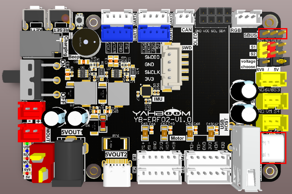
image-20250711093603994

Schematic diagram of the model aircraft remote control and SBUS receiver
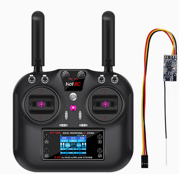
image-20250711102223413

3. Core code analysis

The path corresponding to the program source code is:

xxxxxxxxxx
Board_Samples/STM32_Samples/SBus

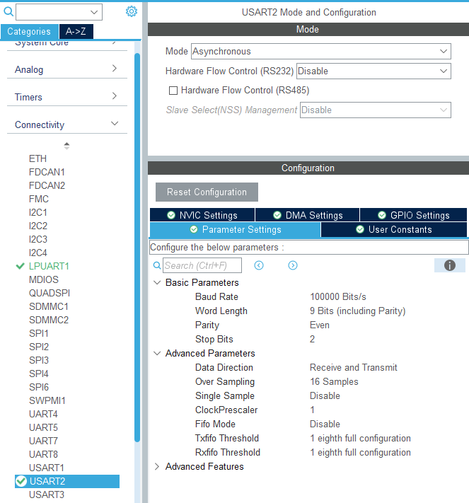
According to the pin assignment, the SBUS signal pin is connected to PA3 (USART2_RX). To meet SBUS communication requirements, a reverse circuit has been added to the hardware circuit. Serial port 2 is initialized with a baud rate of 100,000 bits/s, a data length of 9, stop bits of 2, even parity, and the serial port hardware control setting of None. The serial port receive interrupt function also needs to be enabled.
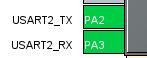
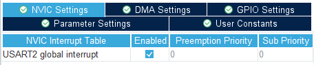
image-20250717092646343image-20250717093002610

image-20250717092727669

xxxxxxxxxx
void MX_USART2_UART_Init(void)
{
  huart2.Instance = USART2;
  huart2.Init.BaudRate = 100000;
  huart2.Init.WordLength = UART_WORDLENGTH_9B;
  huart2.Init.StopBits = UART_STOPBITS_2;
  huart2.Init.Parity = UART_PARITY_EVEN;
  huart2.Init.Mode = UART_MODE_TX_RX;
  huart2.Init.HwFlowCtl = UART_HWCONTROL_NONE;
  huart2.Init.OverSampling = UART_OVERSAMPLING_16;
  huart2.Init.OneBitSampling = UART_ONE_BIT_SAMPLE_DISABLE;
  huart2.Init.ClockPrescaler = UART_PRESCALER_DIV1;
  huart2.AdvancedInit.AdvFeatureInit = UART_ADVFEATURE_NO_INIT;
  if (HAL_UART_Init(&huart2) != HAL_OK)
  {
    Error_Handler();
  }
  if (HAL_UARTEx_SetTxFifoThreshold(&huart2, UART_TXFIFO_THRESHOLD_1_8) != HAL_OK)
  {
    Error_Handler();
  }
  if (HAL_UARTEx_SetRxFifoThreshold(&huart2, UART_RXFIFO_THRESHOLD_1_8) != HAL_OK)
  {
    Error_Handler();
  }
  if (HAL_UARTEx_DisableFifoMode(&huart2) != HAL_OK)
  {
    Error_Handler();
  }
}

Enable the receive interrupt function of serial port 2.

xxxxxxxxxx
HAL_NVIC_SetPriority(USART2_IRQn, 0, 0);
HAL_NVIC_EnableIRQ(USART2_IRQn);

Initialize SBUS and enable receive interrupt.

xxxxxxxxxx
void SBUS_Init(void)
{
    printf("start\n");
    HAL_UART_Receive_IT(&huart2, (uint8_t *)&g_rx_temp, 1);
}

Read the received data in the serial port interrupt.

xxxxxxxxxx
void HAL_UART_RxCpltCallback(UART_HandleTypeDef *huart)
{
    if (huart == &huart2)
    {
        uint8_t rx_data = g_rx_temp;
        HAL_UART_Receive_IT(&huart2, (uint8_t *)&g_rx_temp, 1);
        SBUS_Reveive(rx_data);
    }
}

The BUS receives and processes the data. If it complies with the SBUS receiving protocol, the relevant data is extracted into sbus_data.

xxxxxxxxxx
void SBUS_Reveive(uint8_t rx_data)
{
    uint8_t data = rx_data;
    // If the protocol start flag is met, data is received
    if (sbus_start == 0 && data == SBUS_START)
    {
        sbus_start = 1;
        sbus_new_cmd = 0;
        sbus_buf_index = 0;
        inBuffer[sbus_buf_index] = data;
        inBuffer[SBUS_RECV_MAX - 1] = 0xff;
    }
    else if (sbus_start)
    {
        sbus_buf_index++;
        inBuffer[sbus_buf_index] = data;
    }
​
    // Finish receiving a frame of data
    if (sbus_start & (sbus_buf_index >= (SBUS_RECV_MAX - 1)))
    {
        sbus_start = 0;
        if (inBuffer[SBUS_RECV_MAX - 1] == SBUS_END)
        {
            memcpy(sbus_data, inBuffer, SBUS_RECV_MAX);
            sbus_new_cmd = 1;
        }
    }
}

Parse the sbus_data data to obtain data for sixteen channels.

xxxxxxxxxx
static int SBUS_Parse_Data(void)
{
    g_sbus_channels[0] = ((sbus_data[1] | sbus_data[2] << 8) & 0x07FF);
    g_sbus_channels[1] = ((sbus_data[2] >> 3 | sbus_data[3] << 5) & 0x07FF);
    g_sbus_channels[2] = ((sbus_data[3] >> 6 | sbus_data[4] << 2 | sbus_data[5] << 10) & 0x07FF);
    g_sbus_channels[3] = ((sbus_data[5] >> 1 | sbus_data[6] << 7) & 0x07FF);
    g_sbus_channels[4] = ((sbus_data[6] >> 4 | sbus_data[7] << 4) & 0x07FF);
    g_sbus_channels[5] = ((sbus_data[7] >> 7 | sbus_data[8] << 1 | sbus_data[9] << 9) & 0x07FF);
    g_sbus_channels[6] = ((sbus_data[9] >> 2 | sbus_data[10] << 6) & 0x07FF);
    g_sbus_channels[7] = ((sbus_data[10] >> 5 | sbus_data[11] << 3) & 0x07FF);
    #ifdef ALL_CHANNELS
    g_sbus_channels[8] = ((sbus_data[12] | sbus_data[13] << 8) & 0x07FF);
    g_sbus_channels[9] = ((sbus_data[13] >> 3 | sbus_data[14] << 5) & 0x07FF);
    g_sbus_channels[10] = ((sbus_data[14] >> 6 | sbus_data[15] << 2 | sbus_data[16] << 10) & 0x07FF);
    g_sbus_channels[11] = ((sbus_data[16] >> 1 | sbus_data[17] << 7) & 0x07FF);
    g_sbus_channels[12] = ((sbus_data[17] >> 4 | sbus_data[18] << 4) & 0x07FF);
    g_sbus_channels[13] = ((sbus_data[18] >> 7 | sbus_data[19] << 1 | sbus_data[20] << 9) & 0x07FF);
    g_sbus_channels[14] = ((sbus_data[20] >> 2 | sbus_data[21] << 6) & 0x07FF);
    g_sbus_channels[15] = ((sbus_data[21] >> 5 | sbus_data[22] << 3) & 0x07FF);
    #endif
​
    // Security check, check if the connection is lost or the data is wrong
    // Security detection to check for lost connections or data errors
    failsafe_status = SBUS_SIGNAL_OK;
    if (sbus_data[23] & (1 << 2))
    {
        failsafe_status = SBUS_SIGNAL_LOST;
        printf("SBUS_SIGNAL_LOST\n");
        // lost contact errors Remote control lost contact error
    }
    else if (sbus_data[23] & (1 << 3))
    {
        failsafe_status = SBUS_SIGNAL_FAILSAFE;
        printf("SBUS_SIGNAL_FAILSAFE\n");
        // data loss error data loss error
    }
    return failsafe_status;
}

Then print out the channel value.

xxxxxxxxxx
static void print_data(void)
{
    static int print_count = 0;
    print_count++;
    if (print_count < 10)
    {
        return;
    }
    print_count = 0;
    #if SBUS_ALL_CHANNELS
    printf("%d,%d,%d,%d,%d,%d,%d,%d,%d,%d,%d,%d,%d,%d,%d,%d\r\n",
            g_sbus_channels[0], g_sbus_channels[1], g_sbus_channels[2],
            g_sbus_channels[3], g_sbus_channels[4], g_sbus_channels[5],
            g_sbus_channels[6], g_sbus_channels[7], g_sbus_channels[8],
            g_sbus_channels[9], g_sbus_channels[10], g_sbus_channels[11],
            g_sbus_channels[12], g_sbus_channels[13], g_sbus_channels[14],
            g_sbus_channels[15]);
    #else
    printf("SBus: %d,%d,%d,%d,%d,%d,%d,%d\r\n",
            g_sbus_channels[0], g_sbus_channels[1], g_sbus_channels[2],
            g_sbus_channels[3], g_sbus_channels[4],g_sbus_channels[5],
            g_sbus_channels[6], g_sbus_channels[7]);
    #endif
}

The SBUS_Handle function is called every 10 milliseconds to check whether any data has been parsed and print it out if so.

xxxxxxxxxx
void App_Handle(void)
{
    SBUS_Init();
​
    while (1)
    {
        SBUS_Handle();
        App_Led_Mcu_Handle();
        HAL_Delay(10);
    }
}
​
void SBUS_Handle(void)
{
    if (sbus_new_cmd)
    {
        int res = SBUS_Parse_Data();
        sbus_new_cmd = 0;
        if (res) return;
        
        print_data();
    }
}

4. Compile, download and burn firmware

Select the project to be compiled in the file management interface of STM32CUBEIDE and click the compile button on the toolbar to start compiling.
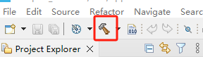
image-20250609174806368

If there are no errors or warnings, the compilation is complete.
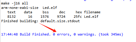
image-20250609175148035

Press and hold the BOOT0 button, then press the RESET button to reset, release the BOOT0 button to enter the serial port burning mode. Then use the serial port burning tool to burn the firmware to the board.

If you have STlink or JLink, you can also use STM32CUBEIDE to burn the firmware with one click, which is more convenient and quick.

5. Experimental Results

The MCU_LED light flashes every 200 milliseconds.

Open the serial port assistant (specific parameters are shown in the figure below), and you can see that the serial port assistant has been printing the data of each channel of the model aircraft remote control. When we manually turn the joystick or button of the model aircraft remote control, the data will change accordingly.
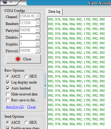
image-20250711102448352

Driving RGB light strip
USB controller remote control

COMPANY

  • About us
  • Team Style
  • Blog

LEARNING & EXPLORATION

  • Tutorials
  • Edge AI hardware
  • Educational robots
  • Embedded intelligent hardware

WHERE TO BUY

  • Yahboom Online Store
  • Amazon
  • Alibaba
  • AliExpress
  • Mercado

TECHNOLOGY SUPPORT

  • Email: support@yahboom.com

BE A DISTRIBUTOR

  • Email: sales@yahboom.com
QR Code

Copyright © 2017-2026 Yahboom. All Rights Reserved.

EN/中文