Welcome to ESP32 Core Board repository
3. Build and Flash
ESP-IDF Build & Flash
ESP-IDF Build & Flash1. Overview2. Prerequisites3. VSCode GUI Build & Flash3.1 Bottom Toolbar3.2 Operation StepsStep 1: Select Target ChipStep 2: Select Serial PortStep 3: BuildStep 4: FlashStep 5: Serial MonitorKeyboard Shortcuts Summary4. Command Line Build & Flash4.1 Launch ESP-IDF Terminal4.2 Common CommandsSet Target ChipBuildFlashSerial MonitorOne-Click OperationClean Build OutputsView Project Configuration5. Flash Download Tool5.1 Installation5.2 Operation StepsStep 1: Launch ToolStep 2: Configure Flash FilesStep 3: Configure Flash ParametersStep 4: Connect & FlashStep 5: Manually Enter Download Mode5.3 Merged Firmware Flashing6. Flash File Description7. Troubleshooting
1. Overview
An ESP-IDF project goes through two steps from source code to running on a development board: Build and Flash. This article covers three operation methods:
| Method | Use Case |
|---|---|
| VSCode GUI | Daily development, one-click build/flash/monitor |
Command Line idf.py | CI/CD, scripting, remote terminal |
| Flash Download Tool | Flashing only pre-compiled .bin firmware, no source environment required |
2. Prerequisites
ESP-IDF environment is installed (refer to Environment Setup (Windows))
USB data cable connected to ESP32-S3 development board
Device Manager recognizes the serial port (e.g.,
COM3)Drivers installed (CP210x / CH340 / CH343 / FT232)
3. VSCode GUI Build & Flash
3.1 Bottom Toolbar
After installing the ESP-IDF extension in VSCode, the bottom status bar will show ESP-IDF toolbar icons:
| Icon | Function | Description |
|---|---|---|
 | Target Chip | Displays current chip model (e.g., esp32s3) |
 | Serial Port | Select the development board's COM port |
 | Build | Build the current project |
 | Flash | Flash compiled output to the development board |
 | Monitor | Open serial monitor to view log output |
 | One-Click Operation | Execute sequentially: Build → Flash → Monitor |
3.2 Operation Steps
Step 1: Select Target Chip
Click the chip selection area on the bottom status bar → Select esp32s3.
ESP-IDF will regenerate
sdkconfigto adapt to ESP32-S3.
Step 2: Select Serial Port
Click the serial port area on the bottom status bar → Select the development board's corresponding COM port.
The bottom status bar should display:
[ESP-IDF] esp32s3 | COM3 | ...
Step 3: Build
Click the Build icon (or press Ctrl + E, B).
Initial build: approximately 2~5 minutes (all components need to be compiled)
Incremental build: only a few seconds (only modified files are recompiled)
The end of the output should display:
xxxxxxxxxxProject build complete.
Build outputs are located in the build/ folder under the project directory:
| File | Description |
|---|---|
bootloader/bootloader.bin | Secondary bootloader |
partition_table/partition-table.bin | Partition table |
*.bin | Application firmware |
flash_args | Flash parameter file |
Step 4: Flash
Click the Flash icon (or press Ctrl + E, F).
The flashing process automatically performs the following:
Put the chip into download mode
Write
bootloader.bin→partition-table.bin→app.binsequentially according to the partition tableAfter flashing completes, the chip automatically resets and the program starts running
Step 5: Serial Monitor
Click the Monitor icon (or press Ctrl + E, M).
The OUTPUT panel will display the chip's serial logs. Press Ctrl + ] to exit monitoring.
Keyboard Shortcuts Summary
| Shortcut | Function |
|---|---|
Ctrl + E, B | Build |
Ctrl + E, F | Flash |
Ctrl + E, M | Monitor |
Ctrl + E, X | One-click: Build + Flash + Monitor |
4. Command Line Build & Flash
4.1 Launch ESP-IDF Terminal
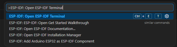
ESP-IDF commands must be run in the EIM Terminal (with ESP-IDF environment variables loaded). F1 → ESP-IDF: Open ESP-IDF Terminal
4.2 Common Commands
Set Target Chip
xxxxxxxxxxidf.py set-target esp32s3Only execute when first setting up or switching chip models. This will regenerate
sdkconfig.
Build
xxxxxxxxxxidf.py buildFlash
xxxxxxxxxxidf.py flashSpecify serial port and baud rate:
xxxxxxxxxxidf.py -p COM3 -b 115200 flash| Parameter | Description |
|---|---|
-p COMx | Specify serial port number |
-b 115200 | Specify flash baud rate |
Serial Monitor
xxxxxxxxxxidf.py monitorExit monitor: Ctrl + ]
One-Click Operation
xxxxxxxxxxidf.py build flash monitorClean Build Outputs
xxxxxxxxxxidf.py fullclean # Full clean (everything except sdkconfig)idf.py clean # Clean build directory onlyView Project Configuration
xxxxxxxxxxidf.py menuconfig5. Flash Download Tool
The ESP Flash Download Tool (Windows GUI tool) is suitable for flashing pre-compiled .bin firmware without installing the ESP-IDF environment.
5.1 Installation
Simply extract 6.软件工具->固件烧录工具->flash_download_tool.zip, no installation required. After extraction, double-click flash_download_tool_x.x.x.exe to use it.
5.2 Operation Steps
Step 1: Launch Tool
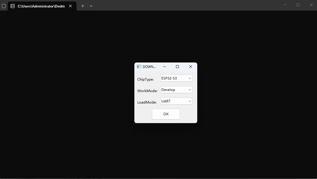
Double-click flash_download_tool_x.x.x.exe → Select chip model ESP32-S3 → Confirm.
Step 2: Configure Flash Files
In the flashing interface, add firmware files and fill in the corresponding flash addresses:
| File | Address | Description |
|---|---|---|
bootloader.bin | 0x0 | Secondary bootloader |
partition-table.bin | 0x8000 | Partition table |
ota_data_initial.bin | 0xd000 | OTA state partition initialization firmware |
AUDIO_PLAYER.bin | 0x10000 | Main application firmware |
File paths cannot contain Chinese characters or spaces, otherwise the tool will fail to parse.

Check the checkbox before each file to activate that flash item.
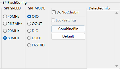
Step 3: Configure Flash Parameters
| Parameter | Recommended Value | Description |
|---|---|---|
| SPI SPEED | 80MHz | SPI Flash clock frequency |
| SPI MODE | QIO | Flash communication mode (Quad I/O) |
| FLASH SIZE | 16Mbit (N16R8) | Select according to actual Flash capacity |
| BAUD | 1152000 | Flash baud rate |
Step 4: Connect & Flash
Select the development board's corresponding COM Port
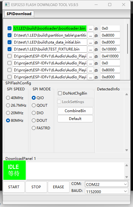
Set baud rate to 1152000
Click START to begin flashing
When the progress bar is full and shows FINISH, it's complete
Step 5: Manually Enter Download Mode
If the tool keeps displaying Waiting for chip to power up, you need to manually put the chip into download mode:
Hold the BOOT button
Press the RST button once (reset)
Release the BOOT button
Some development boards (ESP32-S3-N16R8) require this operation, especially after running other firmware.
5.3 Merged Firmware Flashing
Click the Merge button on the tool interface:  The merge configuration dialog will appear:
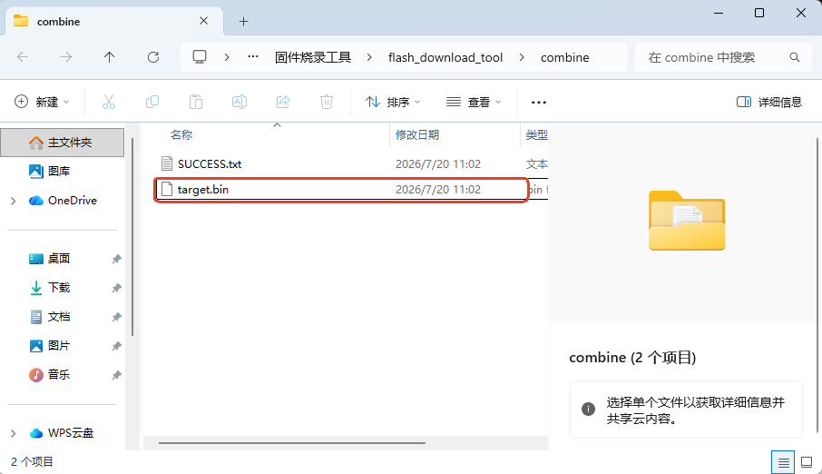
You can rename the merged file (e.g., record and playback.bin):
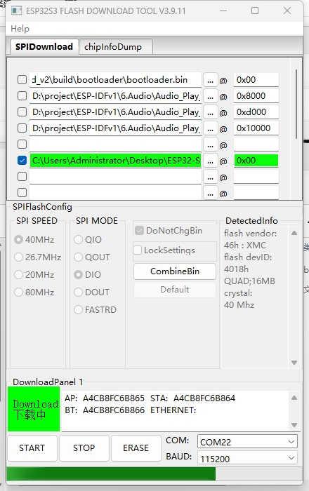
After merging is complete, set the generated .bin file address to 0x0, check it, and flash.
6. Flash File Description
A complete flash typically contains the following files:
xxxxxxxxxxbuild/├── bootloader/│ └── bootloader.bin # Address 0x0 — Secondary bootloader├── partition_table/│ └── partition-table.bin # Address 0x8000 — Partition table├── hello_world.bin # Address 0x10000 — Application firmware├── flash_args # Flash parameters (used by esptool)└── hello_world.elf # ELF file (contains debug info, not flashed)
7. Troubleshooting
| Phenomenon | Cause | Solution |
|---|---|---|
Timed out waiting for packet header | Chip not in download mode | Manual: Hold BOOT → Press RST → Release BOOT, then flash again |
Invalid head of packet | Baud rate too high or driver issue | Lower baud rate: idf.py -b 115200 flash |
A fatal error occurred: Could not open COMx | COM port occupied | Close serial assistant / other VSCode Monitor sessions |
| No serial port in Device Manager | USB driver missing | Install CH340 / CP2102 driver |
| Program doesn't run after flashing | Chip not reset | Press RST button to manually reset; or auto-reset failed after flashing |
FLASH SIZE selected incorrectly | Firmware partition doesn't match hardware | For N16R8 model, select 16Mbit Flash |
| Flash Download Tool file path error | Path contains Chinese/spaces | Move .bin files to an English path (e.g., D:\firmware\) |
| Build succeeded but flashing failed | Serial port not selected or conflict | Check if VSCode bottom status bar COM port is correct |
idf.py: command not found | Not running in EIM terminal | Use F1 → ESP-IDF: Open ESP-IDF Terminal |