Welcome to ESP32 Core Board repository
4. UDP Server Experiment
UDP Server Experiment
UDP Server Experiment1. UDP Server Overview2. Core Concepts2.1 UDP Server Processing Flow2.2 remoteIP() / remotePort()3. Hardware Dependencies4. Project Architecture and Flow5. Source Code Details5.1 Configuration and Global Variables5.2 setup() — Start Server5.3 loop() — Echo Processing6. Operation Flow6.1 Build and Flash6.2 Operation Steps6.3 Verification Methods7. Common Issues
1. UDP Server Overview
UDP server is a "connectionless" service - simply bind to a port, and any client can send datagrams to that port. After the server receives data, it obtains the sender's address via remoteIP() and remotePort() for targeted replies. Compared to TCP servers, UDP doesn't require accept(), doesn't need to maintain connection state, and inherently supports multiple clients.
Typical Application Scenarios:
| Application Type | Example |
|---|---|
| Echo Service | Receive and reply with the same data |
| DNS Server | Resolve domain name requests |
| NTP Server | Provide time synchronization |
2. Core Concepts
2.1 UDP Server Processing Flow
bind(port) → Wait for datagram arrival → recvfrom() get data+sender address → Targeted reply
Key differences from TCP server:
| UDP Server | TCP Server | |
|---|---|---|
| Connection | Connectionless, handle whoever sends | Need accept() to establish connection |
| Multiple Clients | Naturally supported (each datagram independent) | Need to maintain multiple client objects |
| Resources | One socket handles all | One socket per connection |
2.2 remoteIP() / remotePort()
After parsePacket() receives a datagram, it internally records the sender's IP and port. Subsequent calls to remoteIP() and remotePort() retrieve this information for targeted replies. Unlike TCP's client.write(), UDP requires explicitly specifying beginPacket(remoteIP, remotePort) for each reply.
3. Hardware Dependencies
Pure software experiment. Need to connect to router via WIFI-STA first. Client and server must be on the same local network.
4. Project Architecture and Flow
xsetup()├─ connectWiFi()├─ udp.begin(UDP_PORT) // Bind listening port└─ Print server IP and portloop()├─ udp.parsePacket() > 0 ? // Datagram arrived?│ ├─ udp.read(buf) // Read payload│ ├─ Construct "Server Reply: xxx"│ └─ beginPacket(remoteIP(), remotePort()) → write → endPacket└─ delay(10)
5. Source Code Details
Complete source code: Source code → Arduino → 3.Network Communication → UDP_Server → UDP_Server.ino
5.1 Configuration and Global Variables
xxxxxxxxxxWiFiUDP udp;uint16_t UDP_PORT = 8080;5.2 setup() — Start Server
xxxxxxxxxxvoid setup() {  Serial.begin(115200);  connectWiFi();  udp.begin(UDP_PORT);   // socket() → bind(8080)
  Serial.printf("UDP Server started | IP: %s Port: %d\n",                WiFi.localIP().toString().c_str(), UDP_PORT);}
5.3 loop() — Echo Processing
Reply to any received datagram with "Server Reply:
xxxxxxxxxxvoid loop() {  int packetSize = udp.parsePacket();  if (packetSize > 0) {    char buf[128];    int len = udp.read(buf, sizeof(buf) - 1);    buf[len] = '\0';    Serial.printf("Received: %s\n", buf);
    char reply[160];    sprintf(reply, "Server Reply: %s", buf);
    udp.beginPacket(udp.remoteIP(), udp.remotePort());  // Targeted reply    udp.write(reply, strlen(reply));    udp.endPacket();  }  delay(10);}
remoteIP()andremotePort()are only valid afterparsePacket()returns >0 - they correspond to the sender address of the last received datagram.
6. Operation Flow
6.1 Build and Flash
Arduino flashing process: See Arduino → 1. Before Development → 2. Build and Flash.
Build and flash
Use network debugging assistant or UDP client to send data to
ServerIP:8080
6.2 Operation Steps
Step 1: Flash program, record server IP
Build and flash to ESP32-S3 development board. Open serial monitor (baud rate 115200), wait for WiFi connection success, and note down the server IP address printed in serial:
xxxxxxxxxxUDP Server started | IP: 192.168.11.229 Port: 8080
Step 2: Open network debugging assistant, configure UDP client
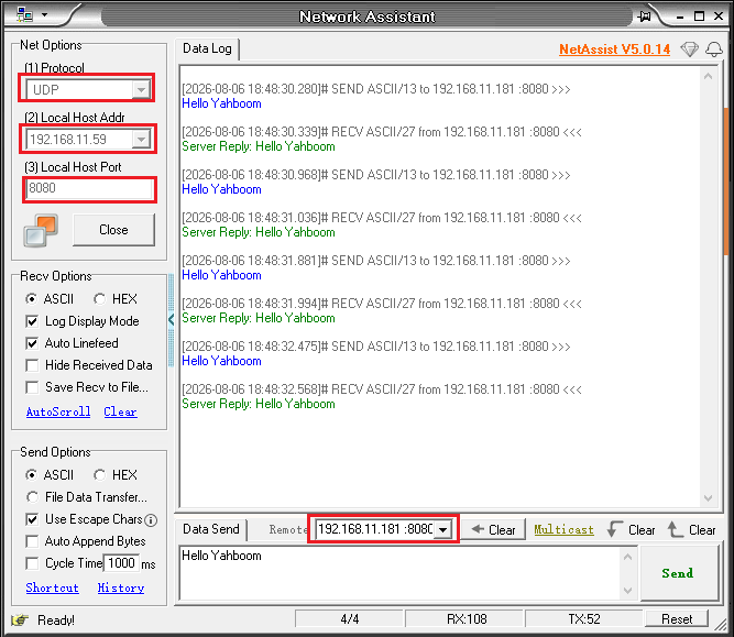
Open network debugging assistant on PC , configure with following parameters:
| Parameter | Value |
|---|---|
| Protocol Type | UDP |
| Remote Host | ESP32 server IP from Step 1 (e.g., 192.168.11.229) |
| Remote Port | 8080 |
Click "Connect" button.
Step 3: Send data, observe echo
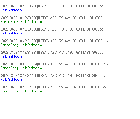
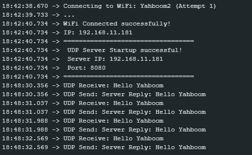
Enter Hello from Client in the send area of network debugging assistant and click send. ESP32 will automatically reply with Server Reply: Hello from Client. Serial monitor and network debugging assistant will print respectively:
Network debugging assistant prints:
Serial monitor prints:
x18:42:38.670 -> Connecting to WiFi: Yahboom2 (Attempt 1)18:42:39.733 -> ...18:42:40.734 -> WiFi Connected successfully!18:42:40.734 -> IP: 192.168.11.18118:42:40.734 -> ==================================18:42:40.734 -> UDP Server Startup successful!18:42:40.734 -> Server IP: 192.168.11.18118:42:40.734 -> Port: 808018:42:40.734 -> ==================================18:48:30.356 -> UDP Receive: Hello Yahboom18:48:30.356 -> UDP Send: Server Reply: Hello Yahboom18:48:31.037 -> UDP Receive: Hello Yahboom18:48:31.037 -> UDP Send: Server Reply: Hello Yahboom18:48:31.988 -> UDP Receive: Hello Yahboom18:48:31.988 -> UDP Send: Server Reply: Hello Yahboom18:48:32.569 -> UDP Receive: Hello Yahboom18:48:32.569 -> UDP Send: Server Reply: Hello Yahboom
Step 4: Verify multi-client support
On another device, also use UDP tool to send data to ESP32's 8080 port. Each client's datagrams will be processed independently and replied to, without interference.
6.3 Verification Methods
| Operation | Expected Result |
|---|---|
| Client sends data | Receive "Server Reply: |
| Multiple clients send simultaneously | Each datagram replied independently, no interference |
7. Common Issues
| Symptom | Cause | Solution |
|---|---|---|
| Client sends but server has no response | Port mismatch | Confirm client sends to port 8080 of server IP |
| Reply cannot be sent | beginPacket used wrong address | Use udp.remoteIP() and udp.remotePort() |