Welcome to ESP32 Core Board repository
10. RGB LED Effects
RGB LED Effects
RGB LED Effects1. WS2812 Overview2. Core Concepts2.1 WS2812 Communication Protocol2.2 RMT Peripheral — Protocol Simulator2.3 led_strip Component Introduction2.4 Rainbow 7-Color Definition3. Project Architecture and Flow4. Hardware Dependencies4.1 Method 1: Open Terminal to Download Official Library:4.2 Method 2: Open idf_component.yml File in main Folder:5. Source Code Analysis5.1 Color Data Structure5.2 led_strip Initialization5.3 Main Loop — Color Switching6. Operation Flow6.1 Hardware Preparation6.2 Build and Flash6.3 Normal Output7. Common Issues
1. WS2812 Overview
WS2812 is an addressable smart LED with integrated control chip and RGB LED. Through a single data line, hundreds of LEDs can be cascade-controlled. Each LED has independent RGB color value (0~255 per channel), supporting 16.77 million colors. Widely used in light strips, ambiance lights, pixel screens, and other scenarios.
This experiment uses RMT (Remote Control Transceiver) peripheral to simulate WS2812 communication protocol, driving one WS2812 to cycle through 7 rainbow colors.
WS2812 Characteristics:
| Feature | Description |
|---|---|
| Communication Interface | Single wire (no clock line), asynchronous self-synchronization |
| Data Format | 24-bit color (G+R+B each 8-bit, GRB order) |
| Cascade Capability | Infinite cascade (each LED forwards data, ≤1024 typical) |
| Refresh Rate | ~30Hz (1024 LEDs) ~2kHz (single LED) |
| Working Voltage | 3.5~5.3V (data signal recommended ≥3.3V) |
Typical Application Scenarios:
| Application Type | Example |
|---|---|
| Consumer electronics | Ambiance lights, gaming peripherals RGB, chassis lighting effects |
| Industrial indication | Equipment status lights (green=normal, red=fault, yellow=standby) |
| Commercial display | LED strips, pixel matrix screens, advertisement light boxes |
| Smart home | Panel backlight, scene lighting, notification lights |
2. Core Concepts
2.1 WS2812 Communication Protocol
WS2812 uses Non-Return-to-Zero (NRZ) encoding, using different duty cycles to represent 0 and 1:
x1-bit encoding:"0" code: ┌──┐ ┌──────────────────── (high ~0.4µs, low ~0.85µs)└──┘ └────────────────────"1" code: ┌─────┐ ┌──────────────── (high ~0.8µs, low ~0.45µs)└─────┘ └────────────────RESET code: ────────────────────────── (low >50µs, indicates frame end)
Data Frame Structure (single LED):
xxxxxxxxxx[G7..G0] [R7..R0] [B7..B0] → RESET (≥50µs low level)├── 24-bit GRB data ──┤Send order: MSB first, each byte high bit firstEach bit takes ~1.25µs, 24-bit totals ~30µs
WS2812 is GRB order, not RGB. Chip datasheet specifies native color order as Green → Red → Blue. Filling RGB values will cause color disorder.
2.2 RMT Peripheral — Protocol Simulator
RMT was originally for infrared remote control, but it's essentially a programmable digital waveform generator, precisely controlling duration of each high/low pulse. WS2812's 1-bit encoding can be perfectly represented by RMT's pulse sequence:
xxxxxxxxxxRMT configuration:Resolution: 10MHz → 1 tick = 0.1µsWS2812 "0": high 4 tick (0.4µs), low 8 tick (0.85µs)WS2812 "1": high 8 tick (0.8µs), low 4 tick (0.45µs)
Why use RMT instead of SPI or bit-bang?
| Solution | Advantage | Disadvantage |
|---|---|---|
| RMT (this experiment) | Hardware auto-generates precise timing, no CPU waiting | Occupies one RMT channel (8 available) |
| SPI | Faster speed | Needs MOSI pin + WS2812 protocol adaptation |
| Bit-bang (GPIO) | Any GPIO, no resource limit | Occupies CPU, timing jitter large, not recommended |
2.3 led_strip Component Introduction
ESP-IDF Component Manager provides espressif/led_strip component, encapsulating WS2812's underlying RMT/SPI operations:
| API | Function |
|---|---|
led_strip_new_rmt_device() | Create RMT-driven WS2812 instance |
led_strip_set_pixel() | Set RGB value for specified pixel |
led_strip_refresh() | Refresh display (send data to LED) |
led_strip_clear() | Clear all pixels (all off) |
led_strip component is introduced through IDF Component Manager (idf_component.yml), automatically downloaded during compilation.
2.4 Rainbow 7-Color Definition
xxxxxxxxxxColor G R B Visual effect─────────────────────────────────────────────Red 0 150 0 Pure redOrange 60 150 0 Red+green → orangeYellow 150 150 0 Red+green full → yellowGreen 150 0 0 Pure greenCyan 150 0 150 Green+blue → cyanBlue 0 0 150 Pure bluePurple 0 120 150 Red+blue → purple
Brightness set to 150 instead of 255 because WS2812 at 255 full brightness has high power consumption and is glaring. 150 at ~59% brightness is more comfortable for experiment environment while reducing power supply ripple.
3. Project Architecture and Flow
xxxxxxxxxxapp_main()├─ led_strip_new_rmt_device() Create RMT WS2812 device│ strip_config: GPIO48, 1 LED, WS2812, GRB format│ rmt_config: 10MHz resolution, DMA disabled│├─ led_strip_clear() All off initial state│└─ while(1) Main Loop├─ printf("Current color: %s") Print current color name├─ led_strip_set_pixel(0, R, G, B) Set pixel 0 RGB├─ led_strip_refresh() Refresh display (send data)├─ color_index++ Switch to next color└─ vTaskDelay(1000ms) Color switch interval
Data Flow:
xxxxxxxxxxrainbow_colors[color_index] Color array (struct {G,R,B})↓led_strip_set_pixel(0, R, G, B) Set pixel 0 RGB value↓led_strip_refresh() Trigger RMT send↓RMT hardware: Convert 24-bit GRB data to pulse sequence↓GPIO48 → WS2812 DIN → LED displays new color
4. Hardware Dependencies
Hardware Connection:
| Pin | Peripheral | Description |
|---|---|---|
| GPIO48 | WS2812 data line (DIN) | RMT pulse output |
| VDD (5V/3.3V) | WS2812 VCC | Power (3.3V can light up but dimmer) |
| GND | Common ground | ESP32-S3 GND ↔ WS2812 GND |
Dependencies: freertos, led_strip (espressif/led_strip via IDF Component Manager)
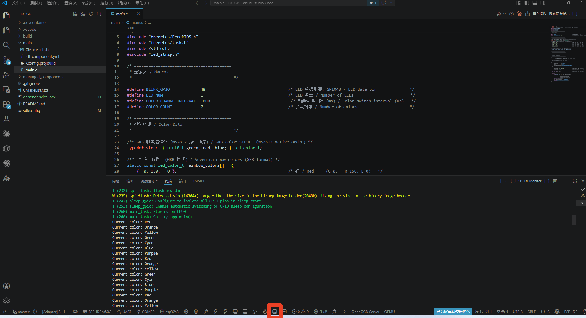
4.1 Method 1: Open Terminal to Download Official Library:
Open ESP-IDF terminal
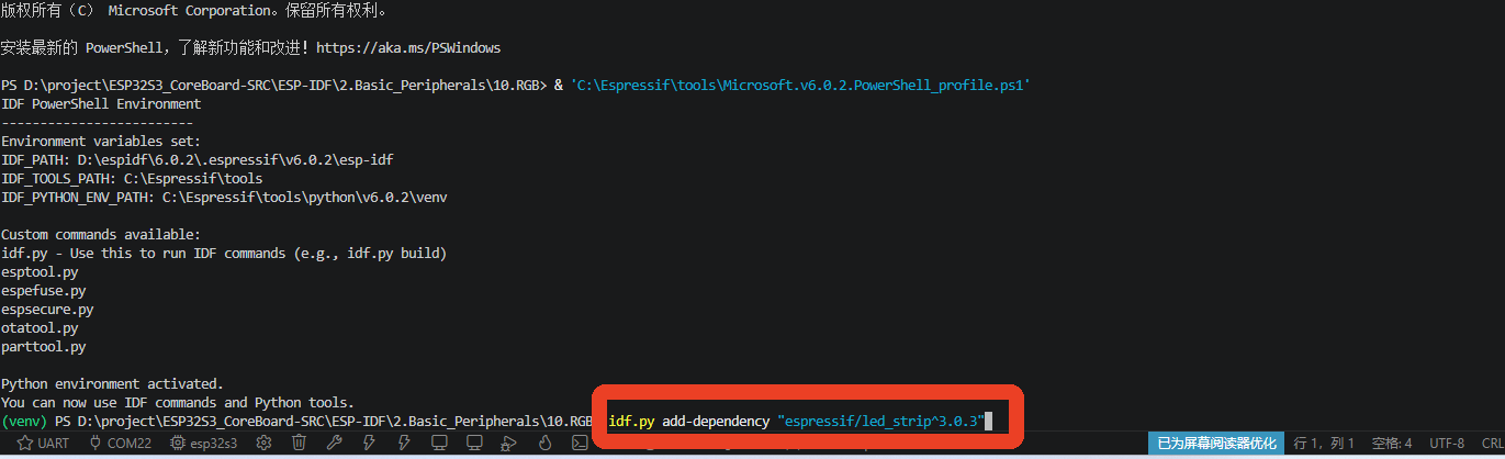
Enter download command in input box
4.2 Method 2: Open idf_component.yml File in main Folder:

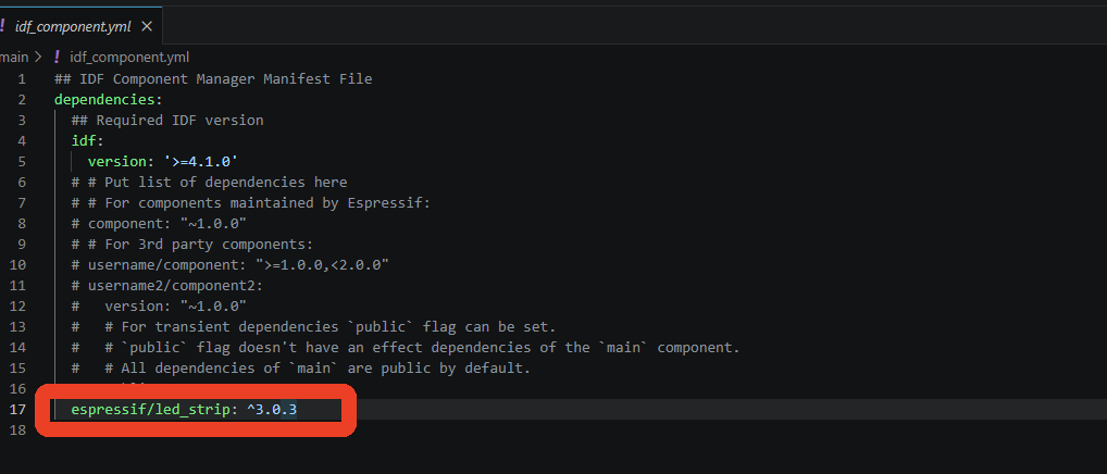
Add led_strip library: Execute the following command in project directory, IDF Component Manager will automatically download and manage dependency.
xxxxxxxxxxidf.py add-dependency "espressif/led_strip^3.0.3"
5. Source Code Analysis
5.1 Color Data Structure
First define basic constants—which IO LED is connected to, how many LEDs, how many colors to cycle. Then store each color's RGB value in array, because WS2812's data order is GRB (green→red→blue), so green is written first in struct. Finally configure a string array of color names for serial printing.
xxxxxxxxxx// Number of colors: 7typedef struct { uint8_t green, red, blue;} led_color_t;
// Seven rainbow colors (GRB format)static const led_color_t rainbow_colors[] = { { 0, 150, 0 }, // Red (G=0, R=150, B=0) { 60, 150, 0 }, // Orange (G=60, R=150, B=0) {150, 150, 0 }, // Yellow (G=150, R=150, B=0) {150, 0, 0 }, // Green (G=150, R=0, B=0) {150, 0, 150 }, // Cyan (G=150, R=0, B=150) { 0, 0, 150 }, // Blue (G=0, R=0, B=150) { 0, 120, 150 }, // Purple (G=0, R=120, B=150)};
// Color names (printf, English only)static const char *color_names[] = { "Red", "Orange", "Yellow", "Green", "Cyan", "Blue", "Purple"};Struct member order is green, red, blue: Matches WS2812's native GRB order. When code calls
led_strip_set_pixel(0, color.red, color.green, color.blue), the RGB order passed is handled internally by led_strip becauseLED_STRIP_COLOR_COMPONENT_FMT_GRBis configured.
5.2 led_strip Initialization
Initialization in two steps: first configure LED parameters (pin, number, model, color format), second configure RMT parameters (clock resolution, whether to use DMA). Then call led_strip_new_rmt_device() to create device handle, then led_strip_clear() to turn all LEDs off, ensuring powered-on state is deterministic.
xxxxxxxxxxvoid app_main(void){    led_strip_config_t strip_config = {        .strip_gpio_num          = BLINK_GPIO,    // GPIO48        .max_leds                = LED_NUM,        // 1 LED        .led_model               = LED_MODEL_WS2812,        .color_component_format  = LED_STRIP_COLOR_COMPONENT_FMT_GRB,        // Non-inverted output        .flags.invert_out        = false,    };    led_strip_rmt_config_t rmt_config = {        // 10MHz = 0.1µs/tick (100ns precision)        .resolution_hz  = 10 * 1000 * 1000,        // No DMA (only 1 LED)        .flags.with_dma = false,    };
    ESP_ERROR_CHECK(led_strip_new_rmt_device(&strip_config, &rmt_config, &led_strip));    // Initial all off    led_strip_clear(led_strip);
Why 10MHz? WS2812 timing precision requirement is within ±150ns. 10MHz (100ns/tick) provides sufficient precision, while not having frequency too high causing RMT memory (64 entries/channel) insufficient to store one frame of data.
Why
with_dma = false? Only 1 LED needs 24 RMT entries, far less than RMT memory limit (64/channel). Enabling DMA increases configuration complexity. For controlling hundreds of LEDs, DMA can bypass RMT memory limit.
5.3 Main Loop — Color Switching
After initialization, enter infinite loop: first use printf to print current color name for easy monitoring in serial monitor. Then call led_strip_set_pixel() to fill current color's RGB value, then led_strip_refresh() to send data through RMT, LED changes color. Finally index +1 with modulo for cycling, vTaskDelay 1 second delay before switching to next color.
xxxxxxxxxx    int color_index = 0;    while (1) {        // Print current color        printf("Current color: %s\n", color_names[color_index]);
        // Pixel index 0 (first LED)        led_strip_set_pixel(led_strip, 0,                           rainbow_colors[color_index].red,                           rainbow_colors[color_index].green,                           rainbow_colors[color_index].blue);        // Send data to LED        led_strip_refresh(led_strip);
        // Cycle index        color_index = (color_index + 1) % COLOR_COUNT;        // Delay 1s        vTaskDelay(pdMS_TO_TICKS(COLOR_CHANGE_INTERVAL));    }}
led_strip_set_pixel()parameter order is (R, G, B), different from struct's{G, R, B}definition—because led_strip API uniformly uses (handle, index, R, G, B) interface, color component sorting is handled bycolor_component_formatconfiguration.
printf()instead ofESP_LOGI(): GPIO48 has no conflict with UART0 (unlike GPIO43/44), serial output can be used. Usingprintfto output color name (English only, following project encoding standard), convenient for debugging and confirming current color.
6. Operation Flow
6.1 Hardware Preparation
WS2812 module (or first LED of light strip)
Wiring:
xxxxxxxxxxESP32-S3 WS2812─────────────────────────GPIO48 → DIN (data input)VDD (5V) → VCC (5V brighter)GND → GND (common ground)
5V power supply recommended: 3.3V can light WS2812, but LED color is dim and unstable (WS2812 datasheet requires VIH ≥ 0.7×VDD, at 3.3V supply input high threshold ~2.3V, GPIO's 3.3V output is above that threshold).
6.2 Build and Flash
For detailed flashing process, see: 1. Before Development → 3. Build and Flash
6.3 Normal Output
Serial monitor:
xxxxxxxxxxCurrent color: RedCurrent color: OrangeCurrent color: YellowCurrent color: GreenCurrent color: CyanCurrent color: BlueCurrent color: PurpleCurrent color: Red ← Cycle...
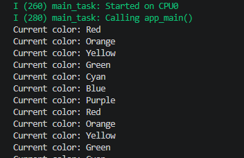
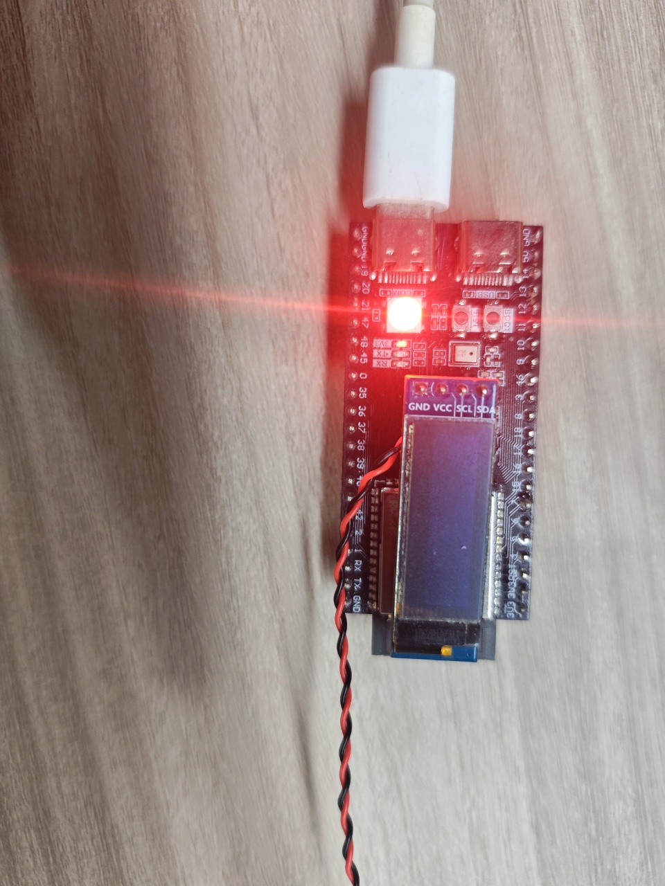
LED phenomenon: Switches one color every 1 second, in order red→orange→yellow→green→cyan→blue→purple→red cycle.
7. Common Issues
| Phenomenon | Cause | Solution |
|---|---|---|
| LED doesn't light up | DIN connected wrong / wrong GPIO / insufficient power | Check wiring, confirm GPIO48; use multimeter to measure VDD voltage |
| Wrong color (red becomes green) | RGB/GRB order configuration error | Confirm color_component_format = LED_STRIP_COLOR_COMPONENT_FMT_GRB |
| LED flickers/random color jumps | Timing imprecise / large power supply ripple | Add 100µF electrolytic capacitor + 0.1µF ceramic capacitor in parallel between VDD-GND |
| When cascading multiple LEDs, first normal, later ones show wrong colors | Later LED data input disturbed / power voltage drop | Solder decoupling capacitor every N LEDs; shorten data line length |
led_strip_new_rmt_device fails | RMT channel resources exhausted | Check if other code occupies RMT channel |
| Doesn't light after first flash | LED state not initialized | led_strip_clear ensures RESET pulse is sent |
| Colors too dim | 3.3V power supply / RGB values too low | Use 5V power supply; increase RGB values (e.g., 255) |