Welcome to ESP32 Core Board repository
9.Low Power Mode
Low Power Mode
Low Power Mode1. Deep Sleep Overview2. Core Concepts2.1 ESP32-S3 Power Mode Comparison2.2 Deep Sleep API2.3 Wakeup Cause Enum2.4 Program Behavior After Deep Sleep3. Project Architecture and Flow4. Hardware Dependencies5. Source Code Analysis5.1 Header Files and Macro Configuration5.2 Functional Decomposition5.2.1 Function Declarations5.2.2 Print Wakeup Cause5.2.3 Pin Configuration5.2.4 Countdown Loop5.2.5 Enter Deep Sleep5.2.6 Main Entry6. Operation Flow6.1 Compilation and Flashing Flow6.2 Power-on Cold Boot6.3 GPIO Wakeup6.4 GPIO4 Prevents Sleep6.5 Button Resets Countdown7. FAQ
1. Deep Sleep Overview
Deep Sleep is the lowest power consumption mode for ESP32-S3. After entering deep sleep, the CPU is completely powered off, RAM content is lost (except RTC memory), and only the RTC domain remains operational, with power consumption dropping to ~5μA.
Importance and Application Scenarios: Deep sleep is the core method for battery-powered IoT devices to achieve long battery life. Typical scenarios include: sensor nodes collect data at intervals then sleep, remote controls send signals on button wakeup, door/window magnetic sensors and other security devices triggered by GPIO level for wakeup. Proper use of deep sleep can extend battery life from hours to months or even years — a technology that must be mastered in low-power product design.
After wakeup, the chip re-executes from app_main() (equivalent to cold boot reset). You can distinguish wakeup reasons via esp_sleep_get_wakeup_cause().
This project demonstrates: 5-second countdown into deep sleep, GPIO4 connected to high level prevents sleep, button resets countdown. GPIO0 low level wakeup.
2. Core Concepts
2.1 ESP32-S3 Power Mode Comparison
| Mode | CPU | RAM | Wakeup Method | Power Consumption | Wakeup Time |
|---|---|---|---|---|---|
| Active | Full speed | Full retention | — | ~tens of mA | — |
| Modem Sleep | Running | Full retention | Any interrupt | ~few mA | — |
| Light Sleep | Paused | Full retention | GPIO/Timer/... | ~0.8mA | ~1ms |
| Deep Sleep | Powered off | Lost (except RTC) | RTC GPIO/Timer | ~5μA | ~1ms (reset) |
| Hibernation | Powered off | Lost | RTC Timer only | ~3μA | ~1ms |
2.2 Deep Sleep API
x// Enable ext0 wakeup (single GPIO level)esp_err_t esp_sleep_enable_ext0_wakeup( gpio_num_t gpio_num, // Wakeup pin // Wakeup level (0=low, 1=high) int level);
// Get wakeup causeesp_sleep_wakeup_cause_t esp_sleep_get_wakeup_cause(void);
// Enter deep sleep (never returns — chip resets)void esp_deep_sleep_start(void);2.3 Wakeup Cause Enum
| Enum Value | Meaning |
|---|---|
ESP_SLEEP_WAKEUP_UNDEFINED | Power-on cold boot (not wakeup) |
ESP_SLEEP_WAKEUP_GPIO | ext0/ext1 GPIO wakeup |
ESP_SLEEP_WAKEUP_TIMER | RTC timer wakeup |
ESP_SLEEP_WAKEUP_TOUCHPAD | Touch sensor wakeup |
ESP_SLEEP_WAKEUP_ULP | ULP coprocessor wakeup |
2.4 Program Behavior After Deep Sleep
xxxxxxxxxxPower-on / Wakeup│▼Bootloader│▼app_main() — Execute from scratch│├─ esp_sleep_get_wakeup_cause() determine cause│ ├─ ESP_SLEEP_WAKEUP_GPIO → "Woken by button"│ └─ ESP_SLEEP_WAKEUP_UNDEFINED → "Power-on cold boot"│└─ Normal execution... → Enter sleep again
3. Project Architecture and Flow
xxxxxxxxxxapp_main()├─ print_wakeup_cause() ← Detect wakeup cause (GPIO wakeup / power-on cold boot)├─ configure_pins() ← Configure GPIO0 (button) and GPIO4 (prevent)├─ run_countdown() ← Countdown main loop (5 seconds, 100ms polling)│ ├─ GPIO4=high → countdown locked at 5 (prevent sleep)│ ├─ Button pressed (≥50ms) → countdown reset to 5│ └─ Every 1 second countdown--└─ enter_deep_sleep() ← Configure ext0 wakeup source and enter deep sleep│▼GPIO0 low level → chip reset → app_main() re-executes
Countdown Parameters:
| Parameter | Value | Meaning |
|---|---|---|
| Countdown initial value | 5 seconds | Sleep after 5 seconds with no prevent/no button |
| Polling period | 100ms | Check GPIO status every 100ms |
| Debounce time | 50ms | Button debounce |
| Wakeup method | ext0 (GPIO0 low level) | Press BOOT button to wakeup |
4. Hardware Dependencies
| Pin | Function | Description |
|---|---|---|
| GPIO 0 | Button + wakeup source | Low level wakeup (ext0 wakeup); pressing also resets countdown |
| GPIO 4 | Sleep prevent pin | High=prevent countdown, low/floating=allow countdown (internal pull-down) |
Required Components: freertos/FreeRTOS, freertos/task, esp_sleep, driver/gpio, esp_log
5. Source Code Analysis
Full source code: Source Code → ESP-IDF → 4.FreeRTOS → 5. LOW_Power
5.1 Header Files and Macro Configuration
Project needs to include FreeRTOS, power management (esp_sleep), and GPIO driver headers, and define runtime parameters like countdown seconds and debounce time.
xxxxxxxxxx// Deep-sleep API// GPIO driver
// Wake-up button// Hold pin (HIGH=hold)// Debounce time// Countdown seconds
static const char *TAG = "DEEP_SLEEP"; // Log tag5.2 Functional Decomposition
app_main() is split into 4 independent static functions, each with single responsibility, easy to read and maintain.
Reading order: Static function definitions are earlier in the file,
app_main()is at the end.
5.2.1 Function Declarations
Forward declarations allow app_main() to be written at the end, keeping the main function visible at a glance.
xxxxxxxxxx// Print wake-up causestatic void print_wakeup_cause(void);// Configure GPIO pinsstatic void configure_pins(void);// Countdown main loopstatic void run_countdown(void);// Enter deep sleepstatic void enter_deep_sleep(void);5.2.2 Print Wakeup Cause
Read wakeup cause register, distinguish GPIO wakeup from power-on cold boot.
xxxxxxxxxxstatic void print_wakeup_cause(void){ // Read wake-up cause uint32_t cause = esp_sleep_get_wakeup_cause(); if (cause & ESP_SLEEP_WAKEUP_GPIO) { ESP_LOGI(TAG, "GPIO Wakeup!"); // GPIO wakeup } else { // Power-on boot ESP_LOGI(TAG, "Power-on Startup"); }}5.2.3 Pin Configuration
Configure two GPIOs: button pin pull-up input for polling debounce, hold pin pull-down input to ensure sleep allowed when floating.
xxxxxxxxxxstatic void configure_pins(void){    /* Button pin (pull-up input, polling debounce only) */    gpio_config_t btn_conf = {        .pin_bit_mask = BIT64(WAKE_UP_PIN),        .mode         = GPIO_MODE_INPUT,             // Input mode        // Pull-up enabled        .pull_up_en   = GPIO_PULLUP_ENABLE,        // Pull-down disabled        .pull_down_en = GPIO_PULLDOWN_DISABLE,        // No ISR, polling only        .intr_type    = GPIO_INTR_DISABLE,    };    ESP_ERROR_CHECK(gpio_config(&btn_conf));
    /* Hold pin (pull-down, floating=0=allow sleep) */    gpio_config_t hold_conf = {        .pin_bit_mask = BIT64(HOLD_PIN),        .mode         = GPIO_MODE_INPUT,             // Input mode        // Pull-up disabled        .pull_up_en   = GPIO_PULLUP_DISABLE,        // Pull-down enabled        .pull_down_en = GPIO_PULLUP_ENABLE,        // No ISR, level-read only        .intr_type    = GPIO_INTR_DISABLE,    };    ESP_ERROR_CHECK(gpio_config(&hold_conf));
    ESP_LOGI(TAG, "BTN GPIO%u + HOLD GPIO%u ready", WAKE_UP_PIN, HOLD_PIN);}
5.2.4 Countdown Loop
Poll at 100ms period, handle GPIO4 hold check, button debounce, and countdown decrement every second simultaneously.
xxxxxxxxxxstatic void run_countdown(void){    // Current countdown    int countdown = COUNTDOWN_SEC;    // 100ms tick counter    int tick_cnt  = 0;    bool       last_hold    = false;    // Prev button (1=released)    bool       btn_prev     = true;    // Button edge tick    TickType_t btn_chg_tick = 0;
    ESP_LOGI(TAG, "Enter deep sleep in %d...", countdown);
    while (countdown > 0) {        // 100ms polling        vTaskDelay(pdMS_TO_TICKS(100));        tick_cnt++;
        /* -- GPIO4 Hold Check -- */        bool hold = (gpio_get_level(HOLD_PIN) != 0); // HIGH=hold
        // Edge-print only        if (hold != last_hold) {            ESP_LOGI(TAG, "GPIO%u %s", HOLD_PIN,                     hold ? "HIGH, holding countdown" : "LOW, countdown resumed");            last_hold = hold;        }
        if (hold) {            // Lock countdown            countdown = COUNTDOWN_SEC;            tick_cnt  = 0;                           // Reset tick            continue;        }
        /* -- Button Debounce (polling) -- */        bool btn_raw = (gpio_get_level(WAKE_UP_PIN) == 0); // 1=pressed
        if (btn_raw != btn_prev) {            // Record edge time            btn_chg_tick = xTaskGetTickCount();            btn_prev = btn_raw;        }
        /* LOW stable ≥ 50ms → confirmed press */        TickType_t now = xTaskGetTickCount();        if (btn_raw && ((now - btn_chg_tick) >= pdMS_TO_TICKS(DEBOUNCE_MS))) {            ESP_LOGI(TAG, "Button pressed! Countdown -> %d s", COUNTDOWN_SEC);            // Reset countdown            countdown = COUNTDOWN_SEC;            tick_cnt  = 0;
            /* Wait release + release debounce */            while (gpio_get_level(WAKE_UP_PIN) == 0) {                // 10ms release poll                vTaskDelay(pdMS_TO_TICKS(10));            }            // Release debounce            vTaskDelay(pdMS_TO_TICKS(DEBOUNCE_MS));            // Confirmed released            btn_prev = true;            continue;        }
        /* -- Countdown Decrement (every 1s) -- */        if (tick_cnt >= 10) {                        // 10×100ms = 1s            tick_cnt = 0;            countdown--;            ESP_LOGI(TAG, "Enter deep sleep in %d...", countdown);        }    }}
5.2.5 Enter Deep Sleep
Configure ext0 wakeup source then call esp_deep_sleep_start(). This function never returns — the chip will reset.
xxxxxxxxxxstatic void enter_deep_sleep(void){ esp_sleep_enable_ext0_wakeup(WAKE_UP_PIN, 0); ESP_LOGI(TAG, "Enter DEEP SLEEP mode"); // Wait UART flush vTaskDelay(pdMS_TO_TICKS(50)); // Sleep (never returns) esp_deep_sleep_start();}5.2.6 Main Entry
app_main() only calls 4 functions, main flow is clear at a glance.
xxxxxxxxxxvoid app_main(void){ // Print wake-up cause print_wakeup_cause(); // Configure GPIO pins configure_pins(); // Countdown loop run_countdown(); // Enter deep sleep enter_deep_sleep();}
BIT64(n)vs1ULL << n:BIT64(n)is a macro provided by ESP-IDF, equivalent to(1ULL << (n)), used for GPIO bit masks exceeding 32 bits — a fixed safe写法.
6. Operation Flow
6.1 Compilation and Flashing Flow
For detailed flashing process, see: 1. Before Development → 3. Build and Flash
6.2 Power-on Cold Boot
xxxxxxxxxxPower-on StartupBTN GPIO0 + HOLD GPIO4 readyEnter deep sleep in 5...Enter deep sleep in 4...Enter deep sleep in 3...Enter deep sleep in 2...Enter deep sleep in 1...Enter DEEP SLEEP mode
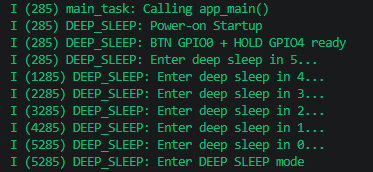
6.3 GPIO Wakeup
Press BOOT button (GPIO0 low level) to wakeup chip:
xxxxxxxxxxGPIO Wakeup! ← Detected GPIO wakeupBTN GPIO0 + HOLD GPIO4 readyEnter deep sleep in 5...

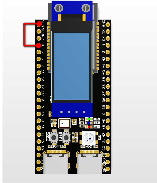
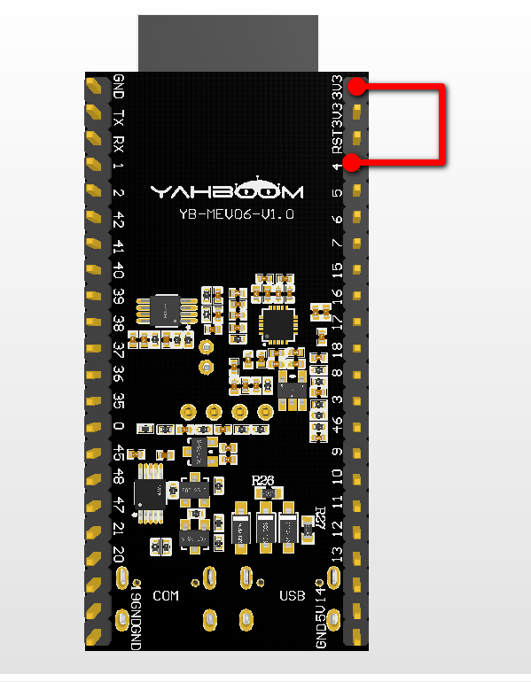
6.4 GPIO4 Prevents Sleep
Connect GPIO4 to 3.3V:
xxxxxxxxxxEnter deep sleep in 5...GPIO4 HIGH, holding countdown ← Countdown locked at 5GPIO4 LOW, countdown resumed ← Resumed after connecting GPIO4 to GND

6.5 Button Resets Countdown
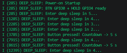
Press BOOT button during countdown:
xxxxxxxxxxEnter deep sleep in 3... ← 3 seconds remainingButton pressed! Countdown -> 5 s ← Reset to 5 secondsEnter deep sleep in 5...
7. FAQ
| Symptom | Cause | Solution |
|---|---|---|
| Cannot sleep again after wakeup | Logic after esp_deep_sleep_start() skipped | Check while(countdown>0) loop logic |
| Button cannot wakeup | ext0 wakeup source config error / level mismatch | Confirm esp_sleep_enable_ext0_wakeup(GPIO0, 0) |
| Garbled output after wakeup | UART buffer not fully flushed | Delay 50ms before esp_deep_sleep_start() |
| GPIO4 floating prevents sleep | Pull-down resistor not configured | Configure pull_down_en = GPIO_PULLDOWN_ENABLE |
| Analog input consumes power during deep sleep | GPIO not configured for RTC domain | Before deep sleep, configure unused GPIOs as GPIO_MODE_DISABLE or RTC GPIO |
| Counter doesn't reset after wakeup | Normal — wakeup=reset, countdown re-initialized to 5 | — |