Welcome to ESP32 Core Board repository
1. Serial UART Communication Experiment
Serial UART Communication Experiment
Serial UART Communication Experiment1. UART Overview2. Core Concepts2.1 Asynchronous Serial Frame Format2.2 Baud Rate and Sampling2.3 Flow Control2.3.1 No Flow Control (None)2.3.2 RTS/CTS Hardware Flow Control2.3.3 XON/XOFF Software Flow Control2.3.4 How to Choose3. ESP32-S3 UART Hardware Specifications4. Project Architecture and Flow5. Hardware Dependencies6. Source Code Details6.1 Header Files and Macro Configuration6.2 uart_init() — Initialization6.3 uart_tx() — Send Data6.4 uart_rx() — Receive Data6.5 app_main() — Entry Point7. Operation Flow7.1 Build and Flash Process7.2 Loopback Test7.3 Edge Cases8. FAQ
1. UART Overview
UART (Universal Asynchronous Receiver/Transmitter) is an asynchronous serial communication protocol that transmits data between devices through two signal lines: TX (Transmit) and RX (Receive), without sharing a clock.
Typical use cases:
| Application | Description |
|---|---|
| Serial Debug / Log Output | Connect to PC serial terminal via UART0 |
| Module Communication | GPS, Bluetooth, Wi-Fi modules, 4G modules, etc. |
| Sensor Data Acquisition | CO₂ sensors, laser ranging, PM2.5, etc. |
| Industrial Control | RS-232 / RS-485 device communication |
| Loopback Test | TX ↔ RX self-transmit/receive to verify hardware and drivers |
This project demonstrates UART1 loopback communication: MCU sends a string via TX, RX receives the echoed data, achieving self-send/self-receive hardware verification.
2. Core Concepts
2.1 Asynchronous Serial Frame Format
UART transmits data in frames (common 8N1 format = 8 data bits + no parity + 1 stop bit):
xIDLE ┌──┐ ┌──┬──┬──┬──┬──┬──┬──┬──┐ ┌──┐│St│ │D0│D1│D2│D3│D4│D5│D6│D7│ │Sp│ IDLE──────┘ │ │ │ │ │ │ │ │ │ │ ├────────└──┘ └──┴──┴──┴──┴──┴──┴──┴──┘ └──┘Start bit ←──── Data bits (LSB first) ────→ Stop bit
| Parameter | Meaning | Common Values |
|---|---|---|
| Baud Rate | Symbols transmitted per second | 9600, 115200, 921600 |
| Data Bits | Data width | 5 / 6 / 7 / 8 |
| Parity | Parity check | None / Even / Odd |
| Stop Bits | Stop bit length | 1 / 1.5 / 2 |
On the same bus, sender and receiver baud rate, data bits, parity, and stop bits must be exactly the same, otherwise garbled text will appear.
2.2 Baud Rate and Sampling
ESP32-S3's UART controller oversamples the RX pin at 16x baud rate clock, sampling near the midpoint of each bit to determine 0/1, avoiding misjudgment due to signal edge jitter.
Principle: The controller continuously samples the RX pin at 16x baud rate clock, taking the sample value near the center of each bit to determine 0/1, thus avoiding the jitter zone at signal edges.
2.3 Flow Control
When the sender continuously sends data to the receiver, if the receiver cannot process fast enough (CPU busy, buffer full, writing to Flash, etc.), data will be lost. Flow control gives the receiver a "pause/continue" notification mechanism, allowing the sender to match the receiver's processing rhythm.
Three flow control methods are described below.
2.3.1 No Flow Control (None)
Only TX and RX two lines, no negotiation between sender and receiver, sender just sends. This is the simplest method, but requires the receiver can always keep up with the sender's rate. Applicable for:
Low-speed communication (e.g., 9600 bps)
Very small data volume, occasional transmission
MCU processing capability far exceeds communication rate
This example scenario: ESP32-S3 handles 20+ bytes effortlessly at 115200 bps, no flow control needed
2.3.2 RTS/CTS Hardware Flow Control
Hardware flow control requires two additional lines: RTS (Request To Send) and CTS (Clear To Send), total TX, RX, RTS, CTS four lines.
Key rule: RTS is local output (telling the other party whether I can receive), CTS is local input (listening to whether the other party allows me to send).
Sender checks its CTS pin before sending:
Peer pulls high → can send
Peer pulls low → pause, wait
Receiver pulls RTS low when RX FIFO is nearly full, notifying the other party "stop sending"; after buffer is emptied, pulls RTS high, notifying "can continue".
Typical wiring is cross connection: local RTS → remote CTS, local CTS → remote RTS.
xxxxxxxxxxSender ReceiverTX ──────────────────────────── RXRX ──────────────────────────── TXRTS ──────── cross ───────────── CTSCTS ──────── cross ───────────── RTS
Timing diagram:
xxxxxxxxxxBuffer status: [Idle] ────→ [Almost full] ────→ [Emptied] ────→ [Idle]RTS signal: ──────────┐ ┌──────────────└──────────┘Pull low (pause peer) Pull high (resume peer)Sender behavior: Normal send ─→ Stop ─────→ Resume sending
ESP32-S3 has built-in RTS/CTS pins. When enabled, the UART controller automatically manages RTS signal level — when RX FIFO reaches configured threshold (e.g., 100 bytes), hardware automatically pulls RTS low; when FIFO drops below safe level, hardware automatically pulls RTS high. The entire process is transparent to software.
Hardware flow control advantages:
Good real-time performance: Hardware signal, fast response
No data bandwidth consumption: Control signals on separate lines
Transparent to software: No need to insert special characters in data
Disadvantages are also obvious:
Two more wires, higher wiring cost
Longer distance wiring requires thicker, more expensive cables
2.3.3 XON/XOFF Software Flow Control
Software flow control does not add extra physical lines, but inserts special characters in the data stream to control the rhythm:
| Character | ASCII Value | Meaning |
|---|---|---|
| XOFF | 0x13 (DC3) | Pause transmission |
| XON | 0x11 (DC1) | Resume transmission |
Workflow:
When receiver cannot keep up, send XOFF (0x13) on reverse channel
Sender receives XOFF and immediately pauses
After receiver finishes processing, send XON (0x11)
Sender receives XON and resumes transmission
xxxxxxxxxxSender Receiver│ │├──────── data ────────────────→ ││ │ Buffer almost full│←────────── XOFF (0x13) ───────┤│ Pause ││ │ Buffer emptied│←────────── XON (0x11) ───────┤├─────── data ──────────────────→││ │
Software flow control advantages:
No extra pins needed: Only TX, RX two lines required
Suitable for pin-constrained or long-distance two-wire communication scenarios
Disadvantages:
Consumes data bandwidth: XON/XOFF characters cannot appear in transmitted data (if data itself contains 0x11/0x13, escape is needed)
Response delay: Special characters must queue for sending, not as instant as hardware signals
Not suitable for binary data transmission (0x11/0x13 may appear frequently, escaping overhead is high)
2.3.4 How to Choose
| Scenario | Recommended Method |
|---|---|
| Low speed, small data, ample MCU performance | No flow control |
| High speed large data (≥ 921600 bps), sufficient pins | RTS/CTS hardware flow control |
| Pin-constrained, printable data (no binary) | XON/XOFF software flow control |
| Full-duplex large data, high real-time requirements | Hardware flow control |
| RS-485 half-duplex | No flow control needed (inherently half-duplex) |
3. ESP32-S3 UART Hardware Specifications
| Feature | Parameter |
|---|---|
| UART Controller Count | 3 (UART0, UART1, UART2) |
| Baud Rate Range | 80 bps ~ 5 Mbps |
| FIFO Depth | 128 bytes × independent transmit/receive |
| Hardware Flow Control | RTS/CTS supported |
| RS-485 Half-Duplex | Supported (DE pin auto-switching) |
| DMA Support | Supported (high throughput scenarios) |
| IRDA Infrared | Supported |
| Wake-up Function | UART wake-up in Light-sleep supported |
Note: UART0 is used for system log and Console output by default. In actual products, UART1 or UART2 is typically used for communication with external devices.
4. Project Architecture and Flow
xxxxxxxxxxapp_main()├─ uart_init() ← Configure UART1 parameters + install driver│ ├─ gpio_config() Configure RX pin internal pull-up│ ├─ uart_param_config() Configure 115200-8N1 no flow control│ ├─ uart_set_pin() Bind TX=GPIO14, RX=GPIO4│ └─ uart_driver_install() Install driver, allocate FIFO buffer│└─ while(1): ← Main loop├─ uart_flush_input() Clear receive buffer├─ uart_tx() Send string + log├─ uart_rx() Wait 100ms read back + log└─ vTaskDelay(2000ms) Delay 2 seconds
5. Hardware Dependencies
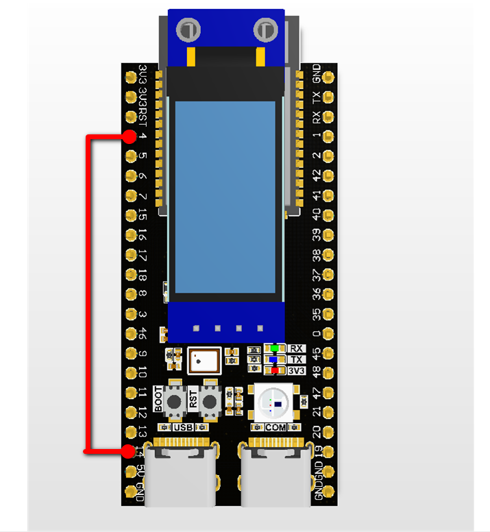
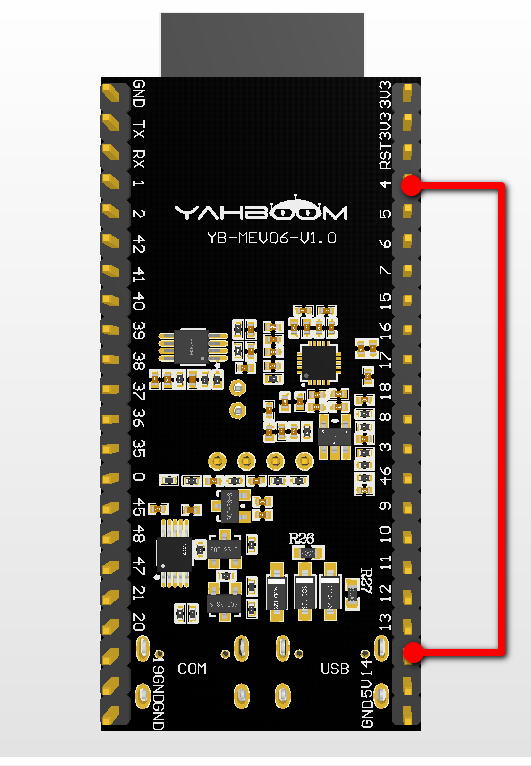
Hardware Connection: GPIO14 (TX) ↔ GPIO4 (RX) shorted (loopback test)
Required Components: driver/uart, driver/gpio, FreeRTOS
6. Source Code Details
6.1 Header Files and Macro Configuration
xxxxxxxxxx
// Log tag// TX pin (GPIO14)// RX pin (GPIO4)// TX & RX buffer size (bytes)Why TX uses GPIO14 and RX uses GPIO4? ESP32-S3's GPIO matrix can map any GPIO to UART peripheral. Choosing GPIO14/GPIO4 only needs to avoid strapping pins already in use (0/3/45/46) and Flash/PSRAM pins (26-37). Different peripheral courses on the same development board (such as DMA) also use this pin combination, facilitating Dupont wire reuse without repeated connection/disconnection.
6.2 uart_init() — Initialization
uart_init() completes four-step configuration:
GPIO Configuration — Set RX pin as input and enable internal pull-up to prevent garbled text when floating.
Parameter Configuration — Set 115200-8N1 (115200 baud rate, 8 data bits, no parity, 1 stop bit, no flow control).
Pin Binding — Bind TX=GPIO14, RX=GPIO4 to UART1 (RTS/CTS not used, pass
UART_PIN_NO_CHANGE).Driver Installation — Allocate 256-byte transmit/receive FIFO buffer for UART1 (queue depth 0, no internal task created).
uart_init() powers on UART1 peripheral, sets parameters, binds pins, installs driver. Four steps complete, ready for transmit/receive.
xxxxxxxxxxstatic void uart_init(void){    /* Config RX pin as input + internal pull-up, avoid garbage on floating */    gpio_config_t rx_config = {        .pin_bit_mask = 1ULL << RXD_PIN,        .mode = GPIO_MODE_INPUT,        .pull_up_en = GPIO_PULLUP_ENABLE,        .pull_down_en = GPIO_PULLDOWN_DISABLE,        .intr_type = GPIO_INTR_DISABLE    };    gpio_config(&rx_config);
    /* 115200 baud, 8 data bits, no parity, 1 stop bit, no flow control */    uart_config_t config = {        .baud_rate = 115200,        .data_bits = UART_DATA_8_BITS,        .parity = UART_PARITY_DISABLE,        .stop_bits = UART_STOP_BITS_1,        .flow_ctrl = UART_HW_FLOWCTRL_DISABLE,    };
    uart_param_config(UART_NUM_1, &config);
    /* Bind TX/RX pins to UART1, RTS/CTS not used */    uart_set_pin(UART_NUM_1, TXD_PIN, RXD_PIN,                 UART_PIN_NO_CHANGE, UART_PIN_NO_CHANGE);
    /* Install UART driver, allocate 256-byte TX/RX FIFO */    uart_driver_install(UART_NUM_1, BUF_SIZE, BUF_SIZE,                        0, NULL, 0);}
6.3 uart_tx() — Send Data
uart_tx() first prints [TX] log via ESP_LOGI(), then calls uart_write_bytes() to write the entire string to TX FIFO, finally calls uart_wait_tx_done() to wait for all data to be sent (max wait 200ms).
uart_tx() prints log first, then puts the string into TX FIFO, finally waits for hardware to finish sending before returning.
xxxxxxxxxxstatic void uart_tx(const char *data){    /* Log first for visibility into what's being sent */    ESP_LOGI(TAG, "[TX] %s", data);
    /* Write the full string into TX FIFO */    uart_write_bytes(UART_NUM_1, data, strlen(data));
    /* Wait for HW to flush all FIFO data (timeout 200ms) */    uart_wait_tx_done(UART_NUM_1, pdMS_TO_TICKS(200));}
6.4 uart_rx() — Receive Data
uart_rx() calls uart_read_bytes() with 100ms timeout to read data. After receiving data, iterates through each byte:
Printable characters (0x20 ~ 0x7E) remain unchanged
Control characters (
\r,\n, etc.) are replaced with.to prevent log display abnormalities
uart_rx() waits 100ms to see if any data comes back. If received, non-printable characters (carriage return, newline, etc.) are uniformly replaced with . to prevent log garbling.
xxxxxxxxxxstatic void uart_rx(void){    uint8_t buf[BUF_SIZE];
    /* Read from RX FIFO, timeout 100ms */    int len = uart_read_bytes(UART_NUM_1, buf, BUF_SIZE - 1,                              100 / portTICK_PERIOD_MS);    if (len > 0) {        /* Replace non-printable chars (\r \n etc.) with '.' for log readability */        for (int i = 0; i < len; i++) {            if (buf[i] < 0x20 || buf[i] > 0x7E) {                buf[i] = '.';            }        }        buf[len] = 0;        ESP_LOGI(TAG, "[RX] %s", buf);    }}
6.5 app_main() — Entry Point
app_main() is the entry point of the entire program: initialize UART1, then in an infinite loop flush buffer → send a sentence → receive back → wait 2 seconds, cycling to verify self-send/self-receive.
xxxxxxxxxxvoid app_main(void){    /* Initialize UART1 */    uart_init();    ESP_LOGI(TAG, "UART Started, TX=GPIO%d, RX=GPIO%d", TXD_PIN, RXD_PIN);
    while (1) {        /* Flush RX buffer to avoid stale data interference */        uart_flush_input(UART_NUM_1);
        /* Send test string */        uart_tx("GOOD GOOD STUDY,DAY DAY UP!!!!!!\r\n");
        /* Read back loopback data */        uart_rx();
        /* Wait 2s before next round */        vTaskDelay(pdMS_TO_TICKS(2000));    }}
Each round first
uart_flush_input()clears residual data to prevent noise from the previous round's unread data from mixing into the current reception.
7. Operation Flow
7.1 Build and Flash Process
For detailed flash process: 1. Before Development → 3. Build and Flash
7.2 Loopback Test
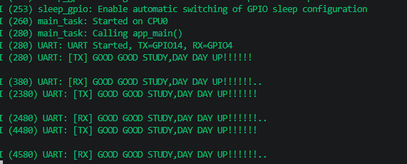
Short GPIO14 (TX) and GPIO4 (RX) with Dupont wire. After powering on, self-send/self-receive once every 2 seconds:
xxxxxxxxxxI (1263) UART: UART Started, TX=GPIO14, RX=GPIO4I (1264) UART: [TX] GOOD GOOD STUDY,DAY DAY UP!!!!!!I (1280) UART: [RX] GOOD GOOD STUDY,DAY DAY UP!!!!!!I (3280) UART: [TX] GOOD GOOD STUDY,DAY DAY UP!!!!!!I (3296) UART: [RX] GOOD GOOD STUDY,DAY DAY UP!!!!!!
In the log, [TX] and [RX] content are exactly the same, indicating hardware and drivers are working normally.
7.3 Edge Cases
No wiring → RX no data: Signal sent by TX has no path back to RX,
uart_read_bytes()times out and returns 0, no[RX]line printed.
8. FAQ
| Symptom | Cause | Solution |
|---|---|---|
| Log output garbled | Terminal baud rate doesn't match code | Set terminal to 115200 (matching code baud_rate) |
[TX] has output but [RX] has none | TX/RX not shorted or wrong pins | Check Dupont wire: GPIO14 ↔ GPIO4 |
Boot error uart_driver_install failed | UART number already in use | UART0 reserved by system, use UART1 or UART2 |
| Occasional byte loss | 100ms timeout too short / buffer too small | Increase BUF_SIZE or extend uart_read_bytes timeout |
| No output, terminal unresponsive | USB-TTL converter not connected or wrong pins | Confirm using USB-TTL module to connect GPIO14/GPIO4: GPIO14 to module RX, GPIO4 to module TX |