Welcome to ESP32 Core Board repository
8. RGB LED Effects
RGB LED Effects
RGB LED Effects1. RGB Colorful Light Overview2. Core Concepts2.1 WS2812 Communication Protocol2.2 WS2812 Color Format — GRB2.3 Seven-Color Rainbow List2.4 Core API — neopixel3. Hardware Dependencies4. Project Architecture and Flow5. Source Code Details5.1 Parameter Configuration and Color Definition5.2 Initialization and Cycle Switching6. Operation Procedure6.1 Flashing and Running6.2 Normal Phenomenon6.3 Verification Methods7. Common Problems
1. RGB Colorful Light Overview
WS2812 (also known as NeoPixel) is a single-wire addressable RGB LED chip. Each LED has a built-in control IC, and only one data wire is needed to cascade and control hundreds of LEDs. This experiment drives the single onboard WS2812 (GPIO48), cycling through 7 rainbow colors, switching once per second while printing the current color name via serial.
Typical application scenarios:
| Application Type | Example |
|---|---|
| Ambient lighting | Music-reactive lights, gaming ambient lights |
| Status indication | Color coding (red=fault, green=normal, blue=connecting) |
| Displays | LED matrix, digital tubes |
| Wearables | LED clothing, glowing accessories |
2. Core Concepts
2.1 WS2812 Communication Protocol
The WS2812 uses a single-wire return-to-zero code: there is only one data wire, and different pulse widths represent 0 and 1.
0 code: ██░░ 0.4μs high + 0.85μs low1 code: ████░░ 0.8μs high + 0.45μs lowRESET: ░░░░ > 50μs low > 50μs = latch signal
Each LED requires 24 bits of data (8 bits each for G-R-B); cascading N LEDs requires 24×N bits. The RESET signal latches the data in the shift register to the output.
2.2 WS2812 Color Format — GRB
The native color order of the WS2812 is GRB (Green-Red-Blue), which differs from the common RGB order:
xxxxxxxxxx# G R BRAINBOW = [ (150, 0, 0), # red: G=0, R=150, B=0 (0, 150, 0), # green: G=150, R=0, B=0 (0, 0, 150), # blue: G=0, R=0, B=150]
(150, 0, 0)in GRB format = G=150, R=0, B=0 → dim green. To write red, use(0, 150, 0): G=0, R=150, B=0.
2.3 Seven-Color Rainbow List
This experiment predefines 7 rainbow colors and cycles through them by array index:
| Index | Color | GRB Value | Visual Effect |
|---|---|---|---|
| 0 | Red | (150, 0, 0) | Red |
| 1 | Orange | (150, 60, 0) | Orange (red+green) |
| 2 | Yellow | (150, 150, 0) | Yellow (red+green equal) |
| 3 | Green | (0, 150, 0) | Green |
| 4 | Cyan | (0, 150, 150) | Cyan (green+blue) |
| 5 | Blue | (0, 0, 150) | Blue |
| 6 | Purple | (120, 0, 150) | Purple (red+blue) |
2.4 Core API — neopixel
xfrom machine import Pinfrom neopixel import NeoPixel
np = NeoPixel(Pin(48), 1) # GPIO48, 1 LEDnp[0] = (150, 0, 0) # set LED 0 to red (GRB)np.write() # send the color data to the LED
np[0] = (g, r, b)only modifies the buffer in memory; you must callnp.write()to actually send it to the LED.
3. Hardware Dependencies
| GPIO | Peripheral | Mode | Description |
|---|---|---|---|
| 48 | WS2812 | Pin.OUT (NeoPixel) | Onboard single RGB LED, data input pin |
The WS2812 on this board is onboard; no external components are required.
4. Project Architecture and Flow
xxxxxxxxxxScript execution (single-file .py)│├─ Config: LED_PIN=48, INTERVAL=1000ms├─ RAINBOW = [7 GRB colors] // predefined color array├─ np = NeoPixel(Pin(48), 1) // 1 WS2812├─ color_index = 0 // color index│└─ while True: // cycle switching├─ print("Current color: ...") // print the current color name├─ np[0] = RAINBOW[color_index] // set the color├─ np.write() // send to the LED├─ color_index = (index + 1) % 7 // cycle the index└─ sleep_ms(1000) // 1s interval
5. Source Code Details
Full source code: 5.Source Code → MicroPython → 1.Basic Peripherals → 8.RGB → 8.RGB.py
5.1 Parameter Configuration and Color Definition
xxxxxxxxxxfrom machine import Pin        # Pin classfrom neopixel import NeoPixel  # WS2812 driverimport time                    # delay
# Configuration parametersLED_PIN  = 48                # LED data pinLED_NUM  = 1                 # number of LEDsINTERVAL = 1000              # color switch interval (ms)
# Seven rainbow colors (GRB order, WS2812 native format)RAINBOW = [    (150, 0,   0),            # Red     (R=150, G=0,   B=0)    (150, 60,  0),            # Orange  (R=150, G=60,  B=0)    (150, 150, 0),            # Yellow  (R=150, G=150, B=0)    (0,   150, 0),            # Green   (R=0,   G=150, B=0)    (0,   150, 150),          # Cyan    (R=0,   G=150, B=150)    (0,   0,   150),          # Blue    (R=0,   G=0,   B=150)    (120, 0,   150),          # Purple  (R=120, G=0,   B=150)]
COLOR_NAMES = ["Red", "Orange", "Yellow", "Green", "Cyan", "Blue", "Purple"]
5.2 Initialization and Cycle Switching
xxxxxxxxxx# Init NeoPixel (WS2812, GPIO48)np = NeoPixel(Pin(LED_PIN), LED_NUM)
color_index = 0
while True:    print("Current color: %s" % COLOR_NAMES[color_index])  # print color
    np[0] = RAINBOW[color_index]  # write to buffer    np.write()                    # send to LED
    color_index = (color_index + 1) % len(RAINBOW)  # cycle index    time.sleep_ms(INTERVAL)
(color_index + 1) % len(RAINBOW)wraps the index back to 0: 6→7→0→1... .
6. Operation Procedure
6.1 Flashing and Running
Thonny IDE steps: See the 1. Before Development → 3.Thonny IDE chapter.
6.2 Normal Phenomenon
The RGB LED switches to one color per second: red→orange→yellow→green→cyan→blue→purple→red, repeating
xxxxxxxxxxCurrent color: RedCurrent color: OrangeCurrent color: YellowCurrent color: GreenCurrent color: CyanCurrent color: BlueCurrent color: PurpleCurrent color: Red ← cycle...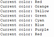
The Shell prints the current color name every second
6.3 Verification Methods
| Operation | Expected Result |
|---|---|
| Power up | LED starts with red, switches every second |
Change INTERVAL=1000 to INTERVAL=200 | Switching speed increases 5 times |
Comment out np.write() | LED color does not update |
| Modify a color value in the RAINBOW array | The corresponding color changes |
| Swap G and R in the RAINBOW array | Colors are clearly wrong (GRB vs RGB) |
7. Common Problems
| Symptom | Cause | Solution |
|---|---|---|
ImportError: no module named 'neopixel' | The firmware does not include the neopixel module | Flash a MicroPython firmware that includes neopixel |
| LED does not light up | np.write() not called | Confirm np.write() is called after every color assignment |
| Color does not match the name (e.g., red becomes green) | Data order uses RGB instead of GRB | Swap the first and second values in the tuple |
| Uneven color brightness | The brightness values of the source colors are not calibrated | Adjust the channel values in the RAINBOW array |
| Serial prints fine but the LED stays white | Powered on before initialization; WS2812 defaults to random | Write black (0,0,0) once before starting the loop |