Welcome to ESP32 Core Board repository
1. Environment Setup
Environment Setup — Arduino IDE + ESP32-S3
Environment Setup — Arduino IDE + ESP32-S31. Overview2. Prerequisites2.1 Hardware Requirements2.2 Downloads Required3. Install CH340 Driver3.1 Check if Driver is Already Installed3.2 Download Driver3.3 Installation Steps3.4 Verification4. Install Arduino IDE5. Install ESP32 Board Package5.1 Add ESP32 Board Manager URL5.2 Install ESP32 Platform via Boards Manager5.3 Select Development Board6. Open Example and Create First Project6.1 Open Blink Example6.2 Create a New Project6.3 Arduino Project File Structure7. Compile, Flash and Monitor7.1 Connect Hardware7.2 Select Board and Port7.3 Compile7.4 Flash7.5 Serial Monitor8. Install Common Libraries8.1 Install via Library Manager9. FAQ
1. Overview
Arduino IDE is an open-source integrated development environment with concise syntax and rich library ecosystem, suitable for rapid prototyping and educational demonstrations.
This tutorial sets up the ESP32-S3 Arduino development environment on Windows, in three steps:
Install Arduino IDE — Download and install Arduino IDE 2.x
Install ESP32 Board Package — Add Espressif's official ESP32 platform support via Boards Manager
Install Driver and Verify — Connect the development board, compile and upload the first program
Arduino IDE 2.x is based on VSCode kernel (Code-OSS), with interface and operation highly similar to VSCode. Espressif officially provides the
arduino-esp32package, supporting all ESP32 series chips (including ESP32-S3).
2. Prerequisites
2.1 Hardware Requirements
| Item | Requirement |
|---|---|
| Operating System | Windows 10 / 11 (64-bit) |
| Disk Space | ≥ 2 GB (Arduino IDE + ESP32 platform ~500 MB + project files) |
| Memory | ≥ 8 GB |
| USB Port | At least 1 USB-A / USB-C (for connecting the development board) |
| Network | Need access to GitHub (to download ESP32 platform and toolchain) |
2.2 Downloads Required
| File | Description | Download Address |
|---|---|---|
| Arduino IDE Installer | Arduino IDE 2.x (skip if already installed) | 6. Software Tools -> Arduino IDE |
No manual download needed for ESP32 platform — all handled online by Arduino IDE's Boards Manager and auto-installed.
3. Install CH340 Driver
ESP32-S3 development boards communicate with the computer via USB-to-serial chip. Most boards use CH340 series chips, which Windows doesn't include by default. Manual installation is required.
3.1 Check if Driver is Already Installed
Connect the development board's COM port to the computer with a USB cable
Right-click Start Menu -> Device Manager -> Expand Ports (COM & LPT)
Check the list:
| Observation | Status | Action |
|---|---|---|
COMx appears (no exclamation mark) | Driver ready | Skip this section |
| Yellow exclamation mark device | Driver missing | Continue installation |
| No new device | USB cable / port issue | Replace cable or USB port |
3.2 Download Driver
WCH Official Download Page -> Download latest CH340SER.EXE (compatible with CH340 series).
You can also search "WCH CH340 driver" to find the official website. The development board in this tutorial uses CH340K, installer is about 300KB.
3.3 Installation Steps
Double-click
CH341SER.EXEClick INSTALL
After installation completes, you should see "Driver install success!"
Replug the development board's USB cable
3.4 Verification
Go to Device Manager -> Ports (COM & LPT), you should see:
USB-SERIAL CH340 (COM3)
Note down the port number (e.g., COM3), needed later for compilation and flashing.
4. Install Arduino IDE
If Arduino IDE 2.x is already installed, skip to Chapter 5.
Double-click Arduino IDE installer (e.g.,
arduino-ide_2.x.x_Windows_64bit.exe)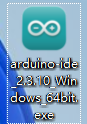
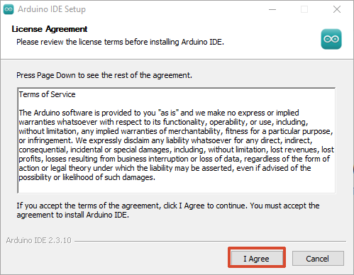
Read license agreement, click I Agree.
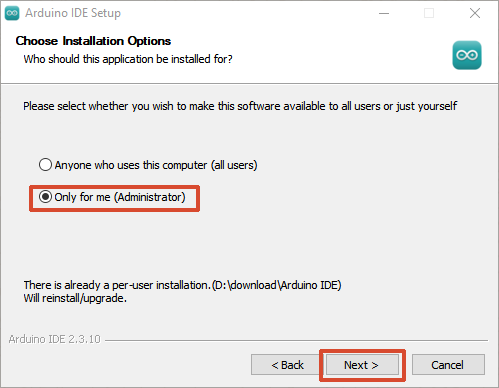
Select installation options (Administrator recommended), click Next.
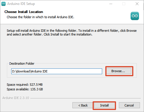
Select installation path (keep default recommended), click Install.
Wait for installation to complete, click Finish.
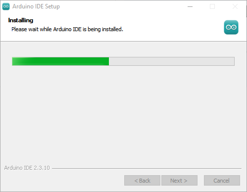
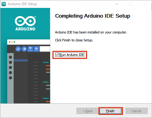
First launch Arduino IDE, interface as follows:
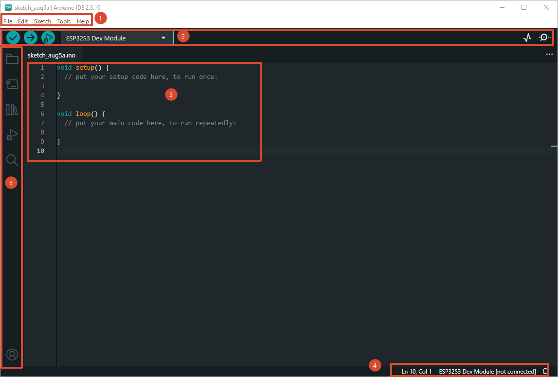
Arduino IDE main interface consists of five areas:
| Number | Area | Description |
|---|---|---|
| ① | Menu Bar | Top horizontal menu bar. File for new/open/save projects and examples; Edit provides copy/paste/comment operations; Sketch for importing libraries and managing code files; Tools centralizes board selection, port, serial monitor and preferences configuration. |
| ② | Toolbar | Row of quick icon buttons below menu bar, left to right: Verify ( Compile, checkmark ✓) only compiles without uploading; Upload ( Compile, checkmark ✓) only compiles without uploading; Upload ( Upload, → icon) compiles and flashes to board; Debug ( Upload, → icon) compiles and flashes to board; Debug ( Debug) starts debugger; Board selection dropdown selects target chip model; Port selection dropdown Debug) starts debugger; Board selection dropdown selects target chip model; Port selection dropdown  selects corresponding COM port; Serial Monitor ( selects corresponding COM port; Serial Monitor ( Serial Monitor) opens serial send/receive panel; Serial Plotter ( Serial Monitor) opens serial send/receive panel; Serial Plotter ( Serial Plotter) plots serial values in real-time waveforms. Serial Plotter) plots serial values in real-time waveforms. |
| ③ | Editor | Central code editor area (VS Code kernel). Supports C/C++ syntax highlighting, auto-completion, code folding, multi-tab pagination (open multiple .ino files simultaneously). Each project has at least one .ino file with the same name, containing setup() (initialization) and loop() (main loop) two core functions. |
| ④ | Status Bar | Bottom banner, left to right displays: Line/column number, Language mode (C++), Current board model (e.g., ESP32S3 Dev Module), Current port (e.g., COM3). During compilation and upload, the bottom will pop up Output panel showing real-time compilation progress, error messages, upload results and Flash usage. |
| ⑤ | Sidebar | Leftmost vertical icon bar.  Folder icon opens Project Browser (Sketchbook); Folder icon opens Project Browser (Sketchbook);  Magnifying glass icon opens Boards Manager Magnifying glass icon opens Boards Manager  to install chip platform packages; to install chip platform packages;  Book icon opens Library Manager to install third-party libraries Book icon opens Library Manager to install third-party libraries  debugger. debugger. |
Arduino IDE 2.x will prompt to install related drivers on first launch, select "Yes" and allow installation.
5. Install ESP32 Board Package
Arduino IDE supports AVR series (Arduino Uno / Nano, etc.) by default. To use ESP32-S3, you need to add Espressif's official board package.
5.1 Add ESP32 Board Manager URL
Open Arduino IDE
Click menu bar File -> Preferences (or press
Ctrl + ,)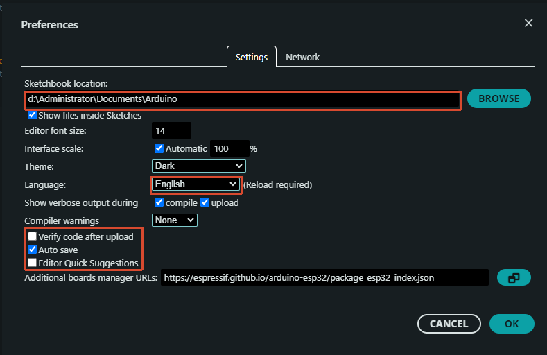
Click the icon on the right side of Additional Boards Manager URLs
 , add the following URL:
xxxxxxxxxxhttps://espressif.github.io/arduino-esp32/package_esp32_index.jsonClick OK to save.
5.2 Install ESP32 Platform via Boards Manager
Click the
Boards Manager icon on left toolbar (or Ctrl + Shift + B)Search "ESP32"
Select "esp32 by Espressif Systems", click Install
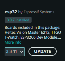
Wait for download and installation to complete (first installation takes about 5~15 minutes, depending on network speed).
Installation includes: ESP32 toolchain (GCC for Xtensa/RISC-V), esptool flashing tool, arduino-esp32 core library (Wi-Fi / BLE / GPIO / I2S, etc.).
After installation completes, Boards Manager should show
INSTALLED.
Local Import:
Usually used for downloading library files or importing custom library files. Here we use the provided libraries folder as an example.
In Arduino IDE interface, select "Sketch -> Import Library -> Add .ZIP Library".
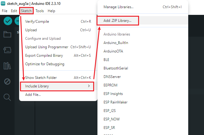
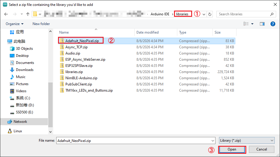
Locate the libarales folder in the same path as the installation package, and add the corresponding compressed file for each library into it. The steps are the same for all folders.
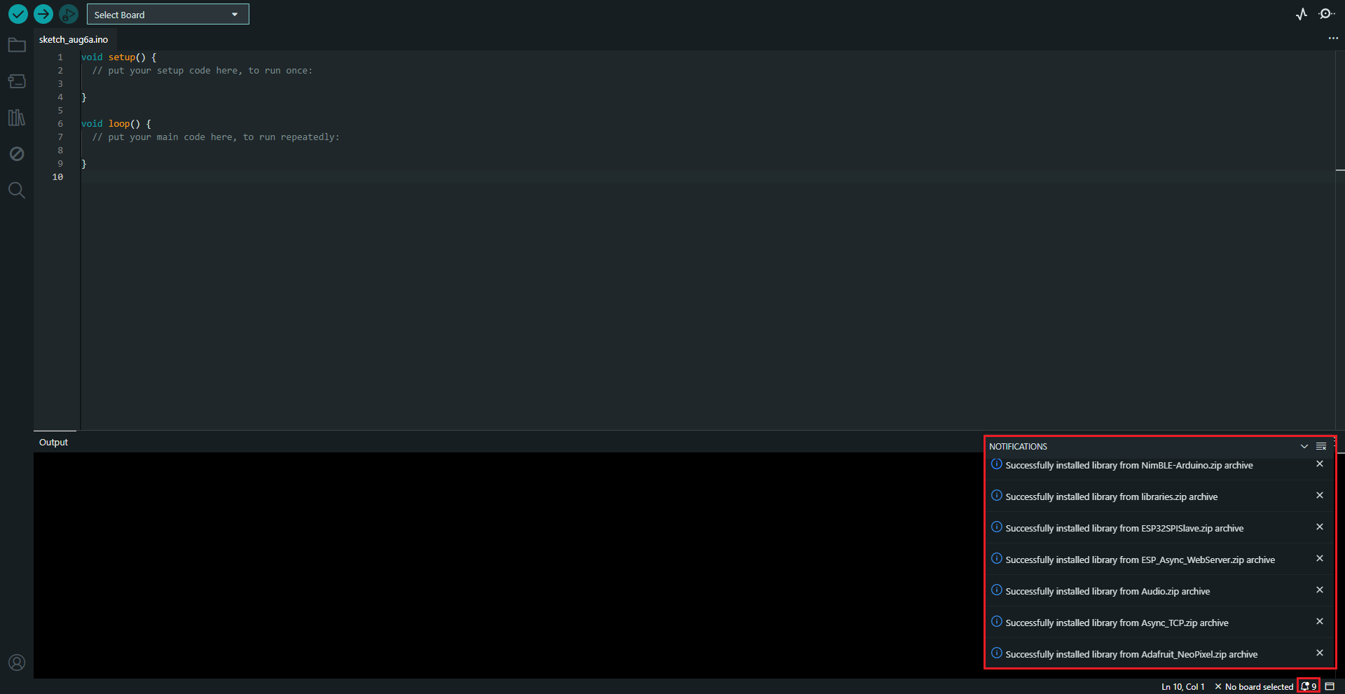
Wait for installation to complete.
5.3 Select Development Board
Click the board selection dropdown on top toolbar
Search "ESP32S3 Dev Module" and select
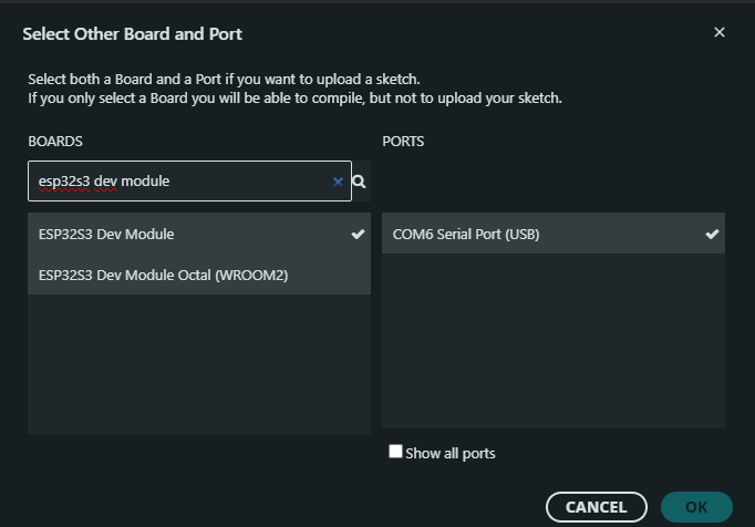
ESP32-S3 Dev Module is a generic configuration suitable for most ESP32-S3 development boards.
After selection, top status bar should display:
xxxxxxxxxxESP32S3 Dev Module | COM6
6. Open Example and Create First Project
6.1 Open Blink Example
Click menu bar File -> Examples -> ESP32 -> GPIO -> Blink
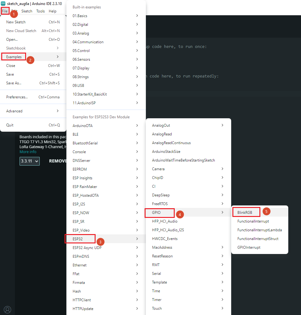
Arduino IDE will open the Blink example. Core code as follows:
x// ESP32-S3 on-board LED pinvoid setup() {// No need to initialize the RGB LED}// the loop function runs over and over again forevervoid loop() {digitalWrite(RGB_BUILTIN, HIGH); // Turn the RGB LED whitedelay(1000);digitalWrite(RGB_BUILTIN, LOW); // Turn the RGB LED offdelay(1000);rgbLedWrite(RGB_BUILTIN, RGB_BRIGHTNESS, 0, 0); // Reddelay(1000);rgbLedWrite(RGB_BUILTIN, 0, RGB_BRIGHTNESS, 0); // Greendelay(1000);rgbLedWrite(RGB_BUILTIN, 0, 0, RGB_BRIGHTNESS); // Bluedelay(1000);rgbLedWrite(RGB_BUILTIN, 0, 0, 0); // Off / blackdelay(1000);}
6.2 Create a New Project
Click menu bar File -> New Sketch
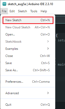
Arduino IDE will create a
.inofile in the default working directory (Documents\Arduino).Ctrl + Sto save, name the project (e.g.,hello_esp32s3).
6.3 Arduino Project File Structure
xxxxxxxxxxhello_esp32s3/└── hello_esp32s3.ino # Main program file (setup + loop)
.inofile — Each Arduino project has at least one.inofile with the same name, containingsetup()(initialization) andloop()(main loop) two core functions.setup()— Runs once after power-on, used to initialize pins, serial, peripherals, etc.loop()— Runs infinitely aftersetup(), equivalent towhile(1)inside a FreeRTOS task.
Arduino framework is based on FreeRTOS underneath:
loop()runs inloopTask(priority 1), Wi-Fi / BLE protocol stacks run in higher priority tasks.
7. Compile, Flash and Monitor
7.1 Connect Hardware
Connect ESP32-S3 development board COM port to computer with USB cable
Open Device Manager -> Expand Ports (COM & LPT)
Confirm new serial port appears (e.g.,
COM6), remember the port numberCommon USB-to-Serial Chips Driver Source CP2102 / CP2104 Silicon Labs CP210x Driver CH340 / CH343 WCH Official Driver CH9102 WCH Official Driver FT232 FTDI Driver If yellow exclamation mark appears, install corresponding driver.
7.2 Select Board and Port
Confirm on top toolbar:
xxxxxxxxxxESP32S3 Dev Module | COM6
Board selection: Dropdown search
ESP32S3 Dev ModulePort selection: Select corresponding COM port
7.3 Compile
Click the Verify (compile) icon on top toolbar (checkmark ✓), or press Ctrl + R.
First compilation takes about 1~3 minutes, incremental compilation only a few seconds. Bottom Output panel should show:
xxxxxxxxxxSketch uses xxx bytes (x%) of program storage space. Maximum is 3145728 bytes.Global variables use xxx bytes (x%) of dynamic memory, leaving xxx bytes for local variables.
7.4 Flash
Click the Upload (upload) icon on top toolbar (→), or press Ctrl + U.
Auto-compiles before flashing. After flashing completes, chip auto-resets and new program starts running.
Some ESP32-S3 development boards require manual entry to download mode for flashing: Hold BOOT button -> Press RST button -> Release BOOT.
7.5 Serial Monitor
Click the Serial Monitor icon on top toolbar, or press Ctrl + Shift + M.
Set baud rate to 115200 in monitor panel to see serial log output from the chip.
8. Install Common Libraries
ESP32 core package already includes GPIO, Wi-Fi, BLE, SPI, I2C and other basic libraries. Install the following as needed for experiments:
8.1 Install via Library Manager
Click the
Library Manager icon on left toolbarSearch library name, click Install
| Library Name | Purpose | Subsequent Experiments |
|---|---|---|
| Adafruit SSD1306 | OLED display driver (I2C) | I2C OLED display experiment |
| Adafruit GFX Library | Graphics library base (SSD1306 dependency) | I2C OLED display experiment |
| Adafruit NeoPixel | WS2812 RGB LED driver | RGB LED Effects |
| SD (by Arduino, SparkFun) | SD card read/write | Flash/SD read/write experiment |
| ArduinoJson | JSON encode/decode | MQTT / HTTP experiment |
| PubSubClient | MQTT client | MQTT IoT experiment |
Simply search library name, select and install. Dependent libraries will be auto-installed.
9. FAQ
| Phenomenon | Cause | Solution |
|---|---|---|
| ESP32 not found in Boards Manager search | ESP32 JSON URL not added | Check Preferences -> Additional Boards Manager URLs has package_esp32_index.json added |
| ESP32 platform installation failed | GitHub network unstable / DNS issue | Retry several times; or use proxy / change DNS |
| Compilation error "missing toolchain" | ESP32 platform package incomplete | Uninstall ESP32 package and reinstall |
| Upload failed "Timed out waiting for packet header" | Chip not in download mode | Hold BOOT -> Press RST -> Release BOOT |
| Upload failed "No serial data received" | Serial port occupied / wrong port | Close other serial tools, confirm correct COM port |
| No serial port in Device Manager | USB driver missing | Install CH340 / CP2102 driver |
| Serial Monitor shows garbled text | Baud rate mismatch | Confirm monitor baud rate matches Serial.begin() |
| Arduino IDE doesn't detect COM port | USB cable only powers, no data transfer | Replace cable (ensure supports data and charging) |
| Upload failed "Wrong chip" | Wrong board model selected | Confirm ESP32S3 Dev Module selected, not ESP32 Dev Module |
| Slow compilation / first upload slow | First-time full compilation | Normal - incremental compilation only a few seconds |