Welcome to ESP32 Core Board repository
2. Build and Flash
Flashing Process
Flashing Process1. Overview2. Firmware Selection2.1 Where to Download2.2 Which Firmware to Choose2.3 Version Selection3. Enter Flashing Mode3.1 Automatic Entry3.2 Manual Entry4. GUI Flashing (Flash Download Tool)4.1 Open the Tool4.2 Configure Flashing Parameters4.3 Start Flashing5. Command-Line Flashing (esptool)5.1 Erase Flash5.2 Flash the Firmware5.3 Flashing Multiple bin Files (Example)5.4 View Flash Information6. Verify the Flashing Result6.1 Verify with a Serial Assistant6.2 Verify with Thonny REPL6.3 Troubleshooting Verification Failures7. Common Problems
1. Overview
The ESP32-S3 does not have MicroPython built in; on power-up it only runs the program already stored in Flash. Therefore, the first time you use it, you need to write the MicroPython firmware into the Flash — this process is called flashing.
Flashing essentially writes the .bin firmware file byte by byte into the chip's SPI Flash over the serial port. After flashing is complete, the ESP32-S3 automatically enters MicroPython REPL on every power-up, with no need to flash again.
This chapter introduces two flashing methods:
| Method | Tool | Suitable Scenario |
|---|---|---|
| Command-line flashing | esptool (pip) | Development and debugging; can be scripted for batch operations |
| GUI flashing | Flash Download Tool | Beginners; visual configuration makes it hard to make mistakes |
For first-time use, try the GUI method first; after you are familiar with the parameters, use the esptool command line for better efficiency.
2. Firmware Selection
2.1 Where to Download
MicroPython officially provides pre-compiled firmware for the ESP32-S3, so you do not need to compile it yourself:
MicroPython ESP32-S3 download page
2.2 Which Firmware to Choose
| Firmware Type | Flash Requirement | PSRAM Requirement |
|---|---|---|
ESP32_GENERIC_S3 | ≥ 8MB | None / ≤ 2MB Octal PSRAM |
ESP32_GENERIC_S3_SPIRAM | ≥ 8MB | ≥ 8MB Quad/Octal PSRAM |
ESP32_GENERIC_S3_SPIRAM_OCT | ≥ 8MB | ≥ 8MB Octal PSRAM |
The board used in this tutorial is the ESP32-S3 N16R8 (16MB Flash + 8MB Octal PSRAM); select the
GENERIC_S3_SPIRAM_OCTfirmware.If you are not sure about the PSRAM type, download the
SPIRAMfirmware without the_OCTsuffix (compatible with both Quad and Octal).
2.3 Version Selection
Download the latest Stable .bin file. The file name format looks like:
ESP32_GENERIC_S3-SPIRAM_OCT-20260406-v1.28.0.bin│ │ │ │Chip platform PSRAM/Flash config Release date Firmware version
Avoid downloading the Nightly Build; it is not stable and is only suitable for trying out new features.
3. Enter Flashing Mode
Before flashing, the chip must enter Download Boot mode so that the ROM Bootloader waits for serial data.
3.1 Automatic Entry
Most ESP32-S3 development boards support automatic downloading — esptool and Flash Download Tool automatically trigger download mode through the RTS/DTR pin timing, so you can just click to flash.
3.2 Manual Entry
If automatic entry fails (showing "Timed out waiting for packet header"), you need to do it manually:
xxxxxxxxxxHold the BOOT key → press the EN key → release BOOT
Timing diagram:
xxxxxxxxxxBOOT ──────┐ ┌──────────────────└─────┘ (hold)EN ──┐ ┌──────────────────────└────┘ (press)← now entering download mode
While holding BOOT, pressing EN resets to the Bootloader; the Bootloader detects BOOT being pulled low and enters download mode.
4. GUI Flashing (Flash Download Tool)
Flash Download Tool is Espressif's official Windows GUI tool, at 6.Software Tools → Firmware flashing tool → flash_download_tool → flash_download_tool_3.9.11.exe.
4.1 Open the Tool
Double-click
flash_download_tool_3.9.11.exeSelect ESP32-S3 for chip type and Develop for work mode, then click OK
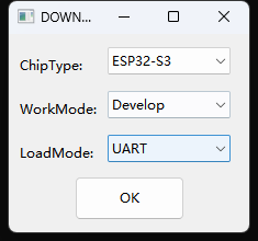
The main interface looks like this:
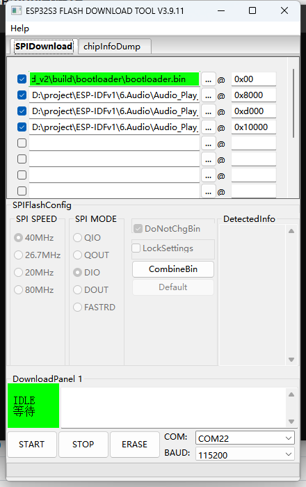
4.2 Configure Flashing Parameters
① Select the firmware file:
Click the
...browse button in the first row and select the downloaded MicroPython.binfileMake sure the start address in the first row is
0x0
② SPI speed:
Select
80MHz(the default; good compatibility)
③ SPI mode:
Select
DIO(dual-line I/O; supported by most boards)If it fails to start after flashing, try
QIO(quad-line I/O)
④ Flash size:
Select
128Mbit(= 16MB), corresponding to the ESP32-S3 N16R8
⑤ COM port:
Select the corresponding port number (
COM3/COM4, etc.)Use the default baud rate
115200or increase it to921600for speed
The higher the serial baud rate, the faster the flashing, but some USB-to-serial chips (especially CH340) are unstable at 921600. If it fails, drop back to 115200 and retry.
4.3 Start Flashing
Confirm the above configuration is correct
Confirm the board is connected and in download mode
Click the START button
When the progress bar completes, FINISH appears and the process is done
After flashing completes, press the RST key on the board to reset and enter MicroPython REPL.
5. Command-Line Flashing (esptool)
esptool is Espressif's official Python CLI flashing tool. The Environment Setup chapter already covered the installation steps (pip install esptool). This section only summarizes the commands for quick reference.
5.1 Erase Flash
xxxxxxxxxxpython -m esptool --chip esp32s3 --port COM3 erase-flash5.2 Flash the Firmware
xxxxxxxxxxpython -m esptool --chip esp32s3 --port COM8 write_flash -z 0x0 "D:\Micropython\ESP32_GENERIC_S3-SPIRAM_OCT-20260406-v1.28.0.bin"| Parameter | Description |
|---|---|
--chip esp32s3 | Target chip model |
--port COM8 | Serial port number (replace with your actual port) |
write-flash | Write to Flash |
-z 0x0 | Firmware start address (ESP32-S3 starts at 0x0) |
5.3 Flashing Multiple bin Files (Example)
Some scenarios require flashing multiple bin files at the same time, such as firmware + file system + partition table, using multiple address pairs:
xxxxxxxxxxesptool --chip esp32s3 --port COM3 write-flash -z \ 0x0 firmware.bin \ 0x8000 partition-table.bin \ 0x10000 littlefs.bin| Address | Content |
|---|---|
0x0 | Firmware (the MicroPython interpreter itself) |
0x8000 | Partition Table |
0x10000 | File system (LittleFS, stores .py scripts) |
The MicroPython single-bin firmware already includes the partition table and a blank file system, so normally you only need to flash the
0x0address. Multiple bins are only used for custom partition scenarios.
5.4 View Flash Information
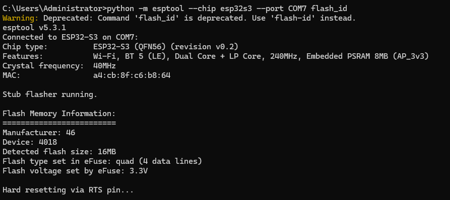
xxxxxxxxxxpython -m esptool --chip esp32s3 --port COM7 flash_idExample output:
xConnected to ESP32-S3 on COM7:Chip type: ESP32-S3 (QFN56) (revision v0.2)Features: Wi-Fi, BT 5 (LE), Dual Core + LP Core, 240MHz, Embedded PSRAM 8MB (AP_3v3)Crystal frequency: 40MHzMAC: a4:cb:8f:c6:b8:64Stub flasher running.Flash Memory Information:=========================Manufacturer: 46Device: 4018Detected flash size: 16MBFlash type set in eFuse: quad (4 data lines)Flash voltage set by eFuse: 3.3VHard resetting via RTS pin...
6. Verify the Flashing Result
After flashing and resetting, use a serial tool to verify:
6.1 Verify with a Serial Assistant
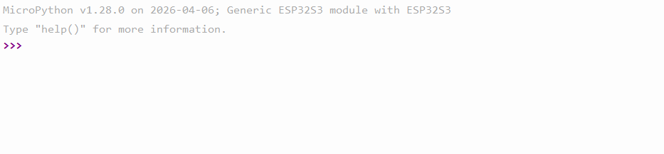
Open any serial assistant (baud rate 115200), connect to the corresponding COM port, press RST to reset, and you should see:
xxxxxxxxxxMicroPython v1.28.0 on 2026-04-06; ESP32S3 module with ESP32S3Type "help()" for more information.>>>
6.2 Verify with Thonny REPL
Connect the ESP32 with Thonny; if >>> appears in the Shell, it is normal.
6.3 Troubleshooting Verification Failures
| Symptom | Possible Cause |
|---|---|
| No output on the serial port | Wrong baud rate; firmware not flashed successfully |
| Garbled output | Baud rate mismatch (MicroPython defaults to 115200) |
Output shows waiting for download | Accidentally entered download mode and did not reset; press EN to exit |
Repeated restarts outputting rst:0x1 | Flash or PSRAM configuration mismatch (wrong firmware selected) |
7. Common Problems
| Symptom | Cause | Solution |
|---|---|---|
| Flash Download Tool cannot find the COM port | Driver not installed | Install the CH340 driver and reopen the tool |
| Flashing progress bar stuck | The chip did not enter download mode | Manually enter download mode with BOOT + EN |
| Cannot start after flashing | Firmware does not match the chip | Confirm the firmware is an ESP32_GENERIC_S3 series |
esptool reports "command not found" | The Python Scripts directory is not in PATH | Close and reopen the terminal, or use python -m esptool |
| Flashing succeeds but PSRAM is unavailable | Firmware does not include PSRAM support | Switch to a SPIRAM version firmware |
| Flash Download Tool shows "COM port occupied" | The serial port is occupied by another program | Close the serial assistant, Thonny, Arduino Monitor, etc. |
| Files in the file system lost after multiple flashes | Flashing erased the entire Flash | Back up the .py files on the device via Thonny before flashing |