Welcome to ESP32 Core Board repository
2. WIFI STA Mode
WIFI STA Mode
WIFI STA Mode1. WiFi STA Overview2. Core Concepts2.1 WiFi Event-Driven Model2.2 EventGroup Synchronization Mechanism2.3 NVS (Non-Volatile Storage)3. ESP32-S3 WiFi Hardware Specifications4. Project Architecture and FlowEvent Handling Flow5. Hardware Dependencies6. Source Code Analysis6.1 Header Files and Macro Configuration6.2 wifi_event_handler() — Event Callback6.3 wifi_init_sta() — WiFi STA Initialization6.4 app_main() — Main Entry7. Operation Flow7.1 Compilation and Flashing Flow7.2 Normal Connection7.3 Disconnect and Reconnect8. Common Problems
1. WiFi STA Overview
WiFi STA (Station, Client Mode) is the most common networking method for ESP32-S3 - allowing the development board to connect to an existing wireless router (AP) like a phone/computer, and after obtaining an IP address, it can access internet or LAN services. STA mode is the foundation of all network applications (UDP/TCP/HTTP/MQTT/OTA upgrade) - devices can only perform data reporting, remote control, firmware upgrade and other IoT core functions after connecting to the network.
| Comparison | STA Mode | AP Mode |
|---|---|---|
| Role | Client (connect to others) | Hotspot (others connect to it) |
| IP Source | DHCP dynamic assignment | Fixed 192.168.4.1 |
| Network Capability | Can access internet | LAN only |
| Typical Scenario | IoT device internet access, data reporting | Configuration provisioning, direct control |
This project implements WiFi STA connection, including automatic reconnection mechanism, and is the foundation for all subsequent network examples (UDP/TCP/HTTP/MQTT).
2. Core Concepts
2.1 WiFi Event-Driven Model
ESP-IDF WiFi uses event-driven (Event-Driven) architecture. WiFi state changes (start, connect, disconnect, get IP) are generated by the underlying layer, developers register callback functions to handle. Callback function handles three core states based on event type: start, disconnect, and get IP.
WiFi state change → WIFI_EVENT / IP_EVENT → event_handler()├─ WIFI_EVENT_STA_START → Auto connect├─ WIFI_EVENT_STA_DISCONNECTED → Clear flag + Reconnect└─ IP_EVENT_STA_GOT_IP → Set flag + Print IP
2.2 EventGroup Synchronization Mechanism
WiFi connection is asynchronous - after esp_wifi_connect() call returns immediately, actual connection result is notified via event callback. This example uses FreeRTOS Event Group to implement synchronized waiting - main thread blocks waiting for result via event group, callback sets bit to unblock.
x// Main thread waits for WiFi connection successxEventGroupWaitBits(wifi_event_group, // Event group handle WIFI_CONNECTED_BIT, // Bit to wait for pdFALSE, // Don't clear on exit pdFALSE, // Wait for any bit timeout); // Block timeout
// Callback: set flag when IP obtainedxEventGroupSetBits(wifi_event_group, WIFI_CONNECTED_BIT);2.3 NVS (Non-Volatile Storage)
WiFi driver depends on NVS for storing calibration data and configuration information. Any program using WiFi must initialize NVS - if NVS partition has no free pages or version mismatch, erase and retry.
xxxxxxxxxx// Initialize NVS flashesp_err_t ret = nvs_flash_init();if (ret == ESP_ERR_NVS_NO_FREE_PAGES || ret == ESP_ERR_NVS_NEW_VERSION_FOUND) { // Erase and recreate if partition is invalid ESP_ERROR_CHECK(nvs_flash_erase()); ret = nvs_flash_init();}3. ESP32-S3 WiFi Hardware Specifications
| Feature | Parameter |
|---|---|
| WiFi Standard | IEEE 802.11 b/g/n |
| Operating Frequency | 2.4 GHz |
| Max Transmit Power | +21 dBm (11b) |
| Max Receive Sensitivity | -97 dBm (11b) |
| Supported Protocols | WPA/WPA2/WPA3 Personal/Enterprise |
| Antenna | On-board ceramic antenna / IPEX external antenna |
| Operating Modes | STA / AP / STA+AP / Sniffer |
| Channel Range | 1 ~ 14 |
Note: WiFi and ADC2 share hardware resources. When WiFi is enabled, use ADC1 for analog acquisition preferentially.
4. Project Architecture and Flow
app_main() entry first initializes NVS flash, then calls wifi_init_sta() to complete WiFi initialization and connection, finally main loop keeps program running. Inside wifi_init_sta(), ESP-IDF standard flow is followed in order: event group creation, network stack initialization, STA interface creation, WiFi driver initialization, event callback registration, STA mode configuration and connection initiation.
xxxxxxxxxxapp_main()├─ nvs_flash_init() ← Initialize NVS flash (required by WiFi)│ └─ If partition abnormal → erase and recreate│├─ wifi_init_sta() ← WiFi STA initialization + connection│ ├─ xEventGroupCreate() → Create event group│ ├─ esp_netif_init() → Initialize TCP/IP network stack│ ├─ esp_event_loop_create_default() → Create default event loop│ ├─ esp_netif_create_default_wifi_sta() → Create STA network interface│ ├─ esp_wifi_init() → Initialize WiFi driver│ ├─ Register event callbacks (WIFI_EVENT + IP_EVENT)│ ├─ esp_wifi_set_mode(WIFI_MODE_STA)│ ├─ esp_wifi_set_config() → Write SSID + Password│ ├─ esp_wifi_start() → Start WiFi│ └─ esp_wifi_connect() → Initiate connection│└─ while(1) { vTaskDelay(1000ms); } ← Keep program running
Event Handling Flow
WiFi driver drives the entire connection lifecycle through three core events - start, disconnect/reconnect, and get IP events form a complete connection state machine.
xxxxxxxxxxWIFI_EVENT_STA_START→ ESP_LOGI "WiFi started"→ (WiFi underlying automatically starts scanning and connecting)WIFI_EVENT_STA_DISCONNECTED→ ESP_LOGI "Disconnected, reconnecting..."→ xEventGroupClearBits(WIFI_CONNECTED_BIT) // Clear connected flag→ esp_wifi_connect() // Auto reconnectIP_EVENT_STA_GOT_IP→ Print obtained IP address→ xEventGroupSetBits(WIFI_CONNECTED_BIT) // Notify other tasks WiFi is ready
5. Hardware Dependencies
Hardware Connection: No external wiring, using on-board WiFi antenna
Dependent Components:
esp_wifi,esp_netif,esp_event,nvs_flash,FreeRTOS,esp_log
6. Source Code Analysis
Complete source code: Source Code → ESP-IDF → 5.Network_Protocol → 1.WiFi_STA
6.1 Header Files and Macro Configuration
Header files introduce required ESP-IDF components: WiFi driver, event group, NVS flash, network interface, etc. Macros centralize WiFi name, password, log tag configuration. WIFI_CONNECTED_BIT is defined as BIT0 to indicate connection status in event group. wifi_event_group is the event group handle, sta_netif is the STA mode network interface object.
xxxxxxxxxx// Task scheduling// Task API// Event group sync// Logging// WiFi driver// Event system// Network interface
// WiFi SSID// WiFi Password// Connection success flag bit
// Log tag
static EventGroupHandle_t wifi_event_group; // Event group handle// Network interface instancestatic esp_netif_t *sta_netif = NULL;6.2 wifi_event_handler() — Event Callback
wifi_event_handler() is the callback handler for WiFi events and IP events, called automatically by system when WiFi state changes. According to event_id, it handles three cases: WIFI_EVENT_STA_START indicates WiFi underlying startup complete, log it; WIFI_EVENT_STA_DISCONNECTED indicates connection disconnected, clear event group flag then call esp_wifi_connect() for auto-reconnect; IP_EVENT_STA_GOT_IP indicates DHCP successfully obtained IP - this is when WiFi is truly usable, notify other tasks via xEventGroupSetBits().
| Event | Handling Logic |
|---|---|
WIFI_EVENT_STA_START | Print log, WiFi underlying ready |
WIFI_EVENT_STA_DISCONNECTED | Clear connection flag → Auto reconnect |
IP_EVENT_STA_GOT_IP | Print IP address → Set event group bit |
xxxxxxxxxxstatic void wifi_event_handler(void* arg, esp_event_base_t event_base, int32_t event_id, void* event_data){ if (event_id == WIFI_EVENT_STA_START) { ESP_LOGI(TAG, "WiFi started"); } else if (event_id == WIFI_EVENT_STA_DISCONNECTED) { // Disconnected — clear flag and reconnect ESP_LOGI(TAG, "Disconnected, reconnecting..."); xEventGroupClearBits(wifi_event_group, WIFI_CONNECTED_BIT); esp_wifi_connect(); } else if (event_id == IP_EVENT_STA_GOT_IP) { ip_event_got_ip_t* event = (ip_event_got_ip_t*) event_data; ESP_LOGI(TAG, "Got IP: " IPSTR, IP2STR(&event->ip_info.ip)); xEventGroupSetBits(wifi_event_group, WIFI_CONNECTED_BIT); }}6.3 wifi_init_sta() — WiFi STA Initialization
wifi_init_sta() executes in ESP-IDF WiFi initialization fixed order: create event group → initialize TCP/IP network stack → create event loop → create STA network interface → initialize WiFi driver → register WiFi and IP event callbacks → configure SSID and password (WPA2 auth) → set STA mode and write config → start WiFi. After esp_wifi_start(), wait 500ms to ensure underlying ready, then call esp_wifi_connect() to initiate connection.
xxxxxxxxxxvoid wifi_init_sta(void){    // Create event group    wifi_event_group = xEventGroupCreate();    // Initialize TCP/IP stack    esp_netif_init();                              // Create default event loop    esp_event_loop_create_default();    // Create STA netif    sta_netif = esp_netif_create_default_wifi_sta();
    wifi_init_config_t cfg = WIFI_INIT_CONFIG_DEFAULT();    // Init WiFi driver    esp_wifi_init(&cfg);
    // Register WiFi and IP event handlers    esp_event_handler_instance_register(WIFI_EVENT, ESP_EVENT_ANY_ID,                                        &wifi_event_handler, NULL, NULL);    esp_event_handler_instance_register(IP_EVENT, IP_EVENT_STA_GOT_IP,                                        &wifi_event_handler, NULL, NULL);
    wifi_config_t wifi_config = {        .sta = {            .ssid = WIFI_SSID,                     // WiFi SSID            .password = WIFI_PASS,                 // WiFi password            .threshold.authmode = WIFI_AUTH_WPA2_PSK, // WPA2 auth        },    };
    // Set STA client mode    esp_wifi_set_mode(WIFI_MODE_STA);    // Apply config    esp_wifi_set_config(WIFI_IF_STA, &wifi_config);    esp_wifi_start();                              // Start WiFi
    // Wait for low-level ready    vTaskDelay(pdMS_TO_TICKS(500));    // Trigger connection    esp_wifi_connect();}
Need to wait 500ms after
esp_wifi_start()to ensure WiFi underlying is ready, immediately callingesp_wifi_connect()may cause crash.
6.4 app_main() — Main Entry
app_main() first initializes NVS flash - WiFi driver's RF calibration parameters depend on NVS storage, so must be called before WiFi initialization. If NVS partition has no free pages or version mismatch, erase and retry. Then calls wifi_init_sta() to start WiFi connection. Finally while(1) infinite loop ensures program doesn't exit, WiFi connection and disconnect reconnect are all handled asynchronously in event callback.
xxxxxxxxxxvoid app_main(void){    // Init NVS flash — required by WiFi driver    esp_err_t ret = nvs_flash_init();    if (ret == ESP_ERR_NVS_NO_FREE_PAGES || ret == ESP_ERR_NVS_NEW_VERSION_FOUND) {        // Erase and recreate if partition is invalid        ESP_ERROR_CHECK(nvs_flash_erase());        ret = nvs_flash_init();    }    ESP_ERROR_CHECK(ret);
    // Start WiFi STA    wifi_init_sta();
    // Infinite loop to keep the task alive    while (1) {        vTaskDelay(pdMS_TO_TICKS(1000));    }}
7. Operation Flow
7.1 Compilation and Flashing Flow
ESP-IDF flashing flow: See ESP-IDF → 1. Before Development → 3. Build and Flash.
7.2 Normal Connection
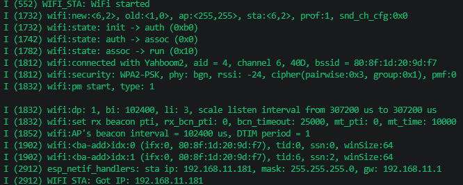
When connection succeeds, serial port outputs complete:
xxxxxxxxxxI (552) WIFI_STA: WiFi started ← WIFI_EVENT_STA_START triggered, WiFi underlying startedI (1732) wifi:new:<6,2>, old:<1,0> ← Switch from channel 1 idle to channel 6, start connectingI (1732) wifi:state: init -> auth (0xb0) ← Initiate 802.11 authentication request to routerI (1742) wifi:state: auth -> assoc (0x0) ← Auth passed, enter association phaseI (1782) wifi:state: assoc -> run (0x10) ← Association successful, physical link establishedI (1812) wifi:connected with Your_WiFi_SSID, aid=4, channel 6, bssid=...← Connection successful, channel 6/40MHz bandwidthI (1812) wifi:security: WPA2-PSK, phy: bgn, rssi: -24 ← WPA2 encryption, 802.11n mode, signal -24dBm (excellent)I (1832) wifi:pm start, type: 1 ← Modem-sleep power saving mode startedI (1852) wifi:AP's beacon interval = 102400 us ← AP sends beacon every 102msI (1902) wifi:<ba-add>idx:0, tid:0, winSize:64 ← Block ACK negotiation, batch acknowledgment improves throughputI (2912) esp_netif_handlers: sta ip: 192.168.11.181, mask: 255.255.255.0, gw: 192.168.11.1I (2912) WIFI_STA: Got IP: 192.168.11.181 ← DHCP obtained IP, WiFi connection fully ready
Key field descriptions:
| Field | Meaning |
|---|---|
init → auth → assoc → run | 802.11 connection state transition: init→auth→assoc→run |
connected with Your_WiFi_SSID | SSID password verified, link layer connection successful |
channel 6, 40D | Current channel 6 (2437MHz), HT40 mode bandwidth |
rssi: -24 | Signal strength -24 dBm, >-50 is excellent |
WPA2-PSK, phy: bgn | WPA2 encryption, 802.11n mode |
pm start, type: 1 | Modem-sleep power saving mode, sleeps when not transmitting data |
ba-add, winSize:64 | Block ACK batch acknowledgment, every 64 frames acknowledged, improves throughput efficiency |
sta ip: 192.168.11.181 | IP address assigned by DHCP |
Got IP | IP_EVENT_STA_GOT_IP event triggered, WiFi truly usable |
7.3 Disconnect and Reconnect
After manually closing router, ESP32 detects disconnection and automatically triggers reconnection:
xxxxxxxxxxI (856) WIFI_STA: WiFi started ← WiFi underlying startedI (1856) WIFI_STA: Got IP: 192.168.11.100 ← First connection successfulI (50256) WIFI_STA: Disconnected, reconnecting... ← Disconnection detected, auto reconnectI (51256) WIFI_STA: Got IP: 192.168.11.100 ← Reconnection successful
8. Common Problems
| Symptom | Cause | Solution |
|---|---|---|
| Continuously prints "Disconnected, reconnecting..." | SSID or password incorrect | Check WIFI_SSID and WIFI_PASS macros |
Compilation error nvs_flash.h not found | NVS not initialized | Add nvs_flash_init() at beginning of app_main() |
| Got IP but can't ping external network | Router not connected to internet / DNS issue | Ping router IP first to confirm LAN connectivity |
esp_wifi_connect() returns error | WiFi initialization not complete | Ensure esp_wifi_start() followed by vTaskDelay(500ms) |
| Connecting to 5G WiFi fails | ESP32-S3 only supports 2.4G | Ensure router 2.4G band is enabled |
WIFI_EVENT_STA_DISCONNECTED triggers frequently | Weak signal or crowded router channel | Move closer to router / Change WiFi channel |
WiFi connection is the prerequisite for all subsequent network examples. If this project cannot connect to router normally, first troubleshoot SSID/password/frequency band, all subsequent UDP/TCP/HTTP/MQTT examples depend on this project's base code.