Welcome to ESP32 Core Board repository
5. USB Emulated Mass Storage
USB Emulated Mass Storage Experiment
USB Emulated Mass Storage Experiment1. USB Emulated Mass Storage Overview2. Core Concepts2.1 USB MSC Protocol Stack2.2 WL Handle Handover Issue2.3 Wear-Leveling2.4 NOR Flash Writes Must Erase First2.5 Reason for ESP-IDF API Mixing3. Hardware Dependencies4. Project Architecture and Flow5. Source Code5.1 Write Preset File5.2 MSC Read/Write Callbacks5.3 setup() — WL Mount and MSC Startup6. Operation Flow6.1 Compile and Flash6.2 Normal Phenomena6.3 Verification Methods7. Common Issues
1. USB Emulated Mass Storage Overview
USB MSC (Mass Storage Class) makes ESP32-S3 emulate a USB flash drive, allowing PC to read and write without installing any driver. This experiment exposes a 1MB FAT partition on SPI Flash to PC via TinyUSB: creates welcome.txt in the partition after power-on, then starts the USB MSC device stack, and PC recognizes it as a readable and writable FAT-formatted flash drive.
Typical Application Scenarios:
| Application Type | Examples |
|---|---|
| Data Export | Export sensor records as CSV files, read by unplugging flash drive style |
| Configuration Update | Modify config files on PC, insert device back for auto-activation |
| Firmware Upgrade | Drag firmware file into flash drive, device auto OTA after restart |
| File Exchange | PC driver-free file access for voice recorders, data loggers |
2. Core Concepts
2.1 USB MSC Protocol Stack
USB MSC is one of the standard device classes defined by the USB organization, allowing embedded devices to emulate storage devices (flash drives, mobile hard drives). PC communicates with the device via standard SCSI command set without installing any driver.
PC Side ESP32-S3 Side┌────────────────┐ ┌──────────────────┐│ File Manager │ │ welcome.txt ││ FATFS │ SCSI Commands │ FFat (FATFS) ││ USB Host Driver │←──READ/WRITE──→│ wl_read/wl_write ││ (Hardware) │ USB Packets │ Wear-Leveling │└────────────────┘ │ SPI Flash │└──────────────────┘
SCSI Command to Project Implementation Mapping:
| SCSI Command | Function | Project Implementation |
|---|---|---|
| READ(10) / READ(12) | PC reads sector data | onRead(lba, offset, buf, size) → wl_read() |
| WRITE(10) / WRITE(12) | PC writes sector data | onWrite(lba, offset, buf, size) → wl_erase_range() + wl_write() |
| START STOP UNIT | PC ejects/mounts media | onStartStop(power, start, eject) → returns true |
| INQUIRY | Query device info (vendor/product ID) | Auto-handled by TinyUSB, no callback needed |
| READ CAPACITY | Query disk capacity (sectors × 512) | Auto-handled by TinyUSB, no callback needed |
The entire chain: PC File Manager → FATFS translates operations to sector read/write → SCSI commands → USB packets → TinyUSB → Callback functions → WL read/write → SPI Flash hardware.
2.2 WL Handle Handover Issue
The core design challenge of this experiment: FFat and USB MSC cannot simultaneously hold the WL handle.
xPhase 1: Write preset fileFFat.begin("storage") ─→ Internally calls wl_mount() to get WL handleFile.write(welcome.txt) ─→ Writes to Flash via WL handleFFat.end() ─→ Internally calls wl_unmount() to release WL handlePhase 2: USB MSC runningwl_mount(part, &wl_handle) ─→ Re-acquire WL handleUSB.begin() ─→ MSC callbacks read/write Flash via this handle
Why can't they share? FFat internally encapsulates FATFS + WL and exclusively owns the WL handle without exposing it. If we call wl_mount() before FFat.end(), it will fail (handle already in use). Therefore, FFat must be completely unmounted first, then WL mounted separately.
2.3 Wear-Leveling
SPI Flash has an erase/write cycle limit per sector (about 100,000 times). If a sector is repeatedly erased/written (e.g., PC repeatedly modifies the same file), that sector will fail quickly. The WL layer solves this through three mechanisms:
Address Remapping: Logical sector numbers don't directly map to physical sector numbers; WL maintains a mapping table
Write Distribution: Each write allocates a different physical sector, avoiding "hot spot" concentrated wear
Garbage Collection: Marks old pages as invalid, background async erase and recovery
xxxxxxxxxxLogical sectors (seen by PC) Physical sectors (actual Flash)LBA 0 ───────────────→ Physical sector 12LBA 1 ───────────────→ Physical sector 47LBA 2 ───────────────→ Physical sector 3... (each write may remap)
2.4 NOR Flash Writes Must Erase First
NOR Flash physical constraint: write operations can only change bits from 1 to 0, not from 0 to 1. The only way to change 0 back to 1 is to erase the entire sector (typically 4KB or larger), after which all bits return to 1.
xxxxxxxxxxCurrent Flash byte value: 1011 0011 (existing data)Value PC wants to write: 0100 1100Direct write: 1011 0011 | 0100 1100 = 1111 1111 ← 1→0 succeeded, but 0→1 didn't work!Correct flow: Erase entire sector first (all become 0xFF) → Write → 0100 1100 ✓
This is why onWrite callback must first wl_erase_range() then wl_write() — if you forget to erase and write directly, the write silently fails, manifesting as file corruption on the PC side.
2.5 Reason for ESP-IDF API Mixing
Arduino framework provides FFat for file-level operations (File.open / File.write), but USB MSC's onRead/onWrite callbacks need block-level (sector-level) Flash access — directly reading/writing 512 bytes given an LBA address. Arduino has no block-level Flash API, so three ESP-IDF interfaces must be mixed:
| Function | Purpose | Arduino Equivalent |
|---|---|---|
esp_partition_find_first() | Find FAT partition in partition table | None |
wl_mount() / wl_size() | Mount wear-leveling layer, get available sector count | None |
wl_read() / wl_write() / wl_erase_range() | Block-level Flash read/write/erase | None |
This is not code style mixing but a limitation of ESP32 platform architecture — TinyUSB MSC must access Flash via block-level interface, and Arduino lacks this layer of abstraction.
3. Hardware Dependencies
| Pin | Peripheral | Configuration | Description |
|---|---|---|---|
| GPIO19 | USB D- | USB OTG | Native USB port differential data negative |
| GPIO20 | USB D+ | USB OTG | Native USB port differential data positive |
ESP32-S3 USB OTG Hardware Features:
| Feature | Parameter |
|---|---|
| USB Controller | USB 2.0 OTG Full-Speed (12 Mbps) |
| Built-in PHY | Yes (no external USB transceiver needed) |
| USB Pins | GPIO19 (D-) / GPIO20 (D+), fixed, cannot remap |
| Supported Device Classes | CDC (serial), MSC (storage), HID (keyboard/mouse), DFU (firmware upgrade) |
| Power Mode | Bus-Powered, max 500mA |
| Low-level Protocol Stack | TinyUSB (built into ESP32 Arduino Core) |
Must use the native USB port to connect to PC. On-board USB-UART port (GPIO43/44) is only for serial monitor. Also requires a
data, fattype partition inpartitions.csv.
4. Project Architecture and Flow
xxxxxxxxxxsetup()├─ writeWelcomeFile() // ① Write welcome.txt using FFat│ ├─ FFat.begin(true, "/ffat", 5, "storage")│ ├─ File.write(welcome.txt)│ └─ FFat.end() // Release WL handle│├─ esp_partition_find_first() // ② Find FAT partition├─ wl_mount(part, &wl_handle) // ③ Remount WL (for MSC use)│├─ MSC configuration // ④ Register callbacks + device info│ ├─ MSC.onRead(onRead)│ ├─ MSC.onWrite(onWrite)│ ├─ MSC.vendorID/productID│ └─ MSC.begin(sectorCount, 512)│└─ USB.begin() // ⑤ Start USB device stack → PC enumeration[USB MSC callbacks - background]├─ onRead → wl_read()├─ onWrite → wl_erase_range() + wl_write()└─ onStartStop → return true
5. Source Code
Source Code Location:
Source code → Arduino → 2.Serial communication → 5.USB → 5.USB.ino
5.1 Write Preset File
Use Arduino FFat API to create welcome.txt in the partition, release WL handle after operation.
xxxxxxxxxxstatic void writeWelcomeFile() { if (!FFat.begin(true, "/ffat", 5, "storage")) return; File f = FFat.open("/welcome.txt", FILE_WRITE); f.println("Welcome to Yahboom USB Mass Storage Demo!"); f.close(); FFat.end(); // Unmount → Release WL handle, make way for MSC}
FFat.end()is the critical step — FFat and USB MSC cannot simultaneously hold the WL handle.
5.2 MSC Read/Write Callbacks
PC calls onRead once per sector read, and onWrite once per sector write. Address calculation: lba * 512 + offset.
xxxxxxxxxxstatic int32_t onRead(uint32_t lba, uint32_t offset, void *buffer, uint32_t bufsize) {  return wl_read(wl_handle, (size_t)lba * 512 + offset, buffer, bufsize)         == ESP_OK ? (int32_t)bufsize : -1;}
static int32_t onWrite(uint32_t lba, uint32_t offset, uint8_t *buffer, uint32_t bufsize) {  wl_erase_range(wl_handle, (size_t)lba * 512, 512);   // NOR Flash must erase before write  return wl_write(wl_handle, (size_t)lba * 512 + offset, buffer, bufsize)         == ESP_OK ? (int32_t)bufsize : -1;}
wl_erase_rangeerases the entire sector (512 bytes). Writing without erasing causes Flash controller to silently fail, manifesting as file corruption on PC side.
5.3 setup() — WL Mount and MSC Startup
Take over WL handle from FFat, configure MSC callbacks, start USB.
xxxxxxxxxxvoid setup() {  Serial.begin(115200);
  writeWelcomeFile();                             // ① Write preset file
  const esp_partition_t *part = esp_partition_find_first(      ESP_PARTITION_TYPE_DATA, ESP_PARTITION_SUBTYPE_DATA_FAT, NULL);  wl_mount(part, &wl_handle);                     // ② Remount WL
  uint32_t sectorCount = wl_size(wl_handle) / 512;
  MSC.vendorID("Espressif");  MSC.productID("ESP32-S3 USB MSC");  MSC.onRead(onRead);  MSC.onWrite(onWrite);  MSC.onStartStop(onStartStop);  MSC.mediaPresent(true);  MSC.isWritable(true);  MSC.begin(sectorCount, 512);                    // ③ Start MSC
  USB.begin();                                    // ④ Start USB device stack  Serial.println("[READY] Plug in the native USB cable");}
6. Operation Flow
6.1 Compile and Flash
Arduino Flash Process: See 1. Before Development → 2. Build and Flash.
Confirm
partitions.csvhasstorage, data, fattype partitionOpen
5.USB.inoBefore flashing, connect native USB port (GPIO19/20) to PC with Type-C data cable
After flashing and powering on, PC immediately recognizes the flash drive
Custom Partition Table Setup:
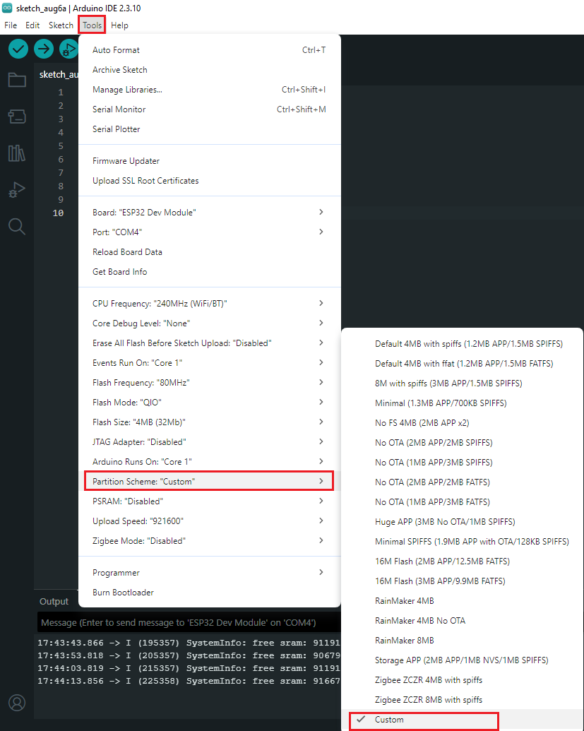
Arduino IDE's default partition scheme doesn't include FAT type partition, requiring manual custom partition table specification:
Tools → Partition Scheme → Select "Custom"
Create
partitions.csvin the Arduino project directory with the following content:
xxxxxxxxxx# Name, Type, SubType, Offset, Sizenvs, data, nvs, 0x9000, 0x6000,factory, app, factory, 0x10000, 1M,storage, data, fat, , 1M,
The partition table defines three partitions: NVS (Wi-Fi/calibration data storage), factory (firmware program), storage (FAT filesystem for MSC flash drive emulation). The storage partition type must be data, fat, size 1MB, offset left blank means immediately after the previous partition.
6.2 Normal Phenomena
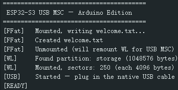
Open Serial Monitor (115200 bps), power on, initialize and print logs:
xxxxxxxxxx========================================ESP32-S3 USB MSC — Arduino Edition========================================[FFat] Mounted, writing welcome.txt...[FFat] Created welcome.txt[FFat] Unmounted (will remount WL for USB MSC)[WL] Found partition: storage (1048576 bytes)[WL] Mounted, sectors: 250 (each 4096 bytes)[USB] Started — plug in the native USB cable[READY]
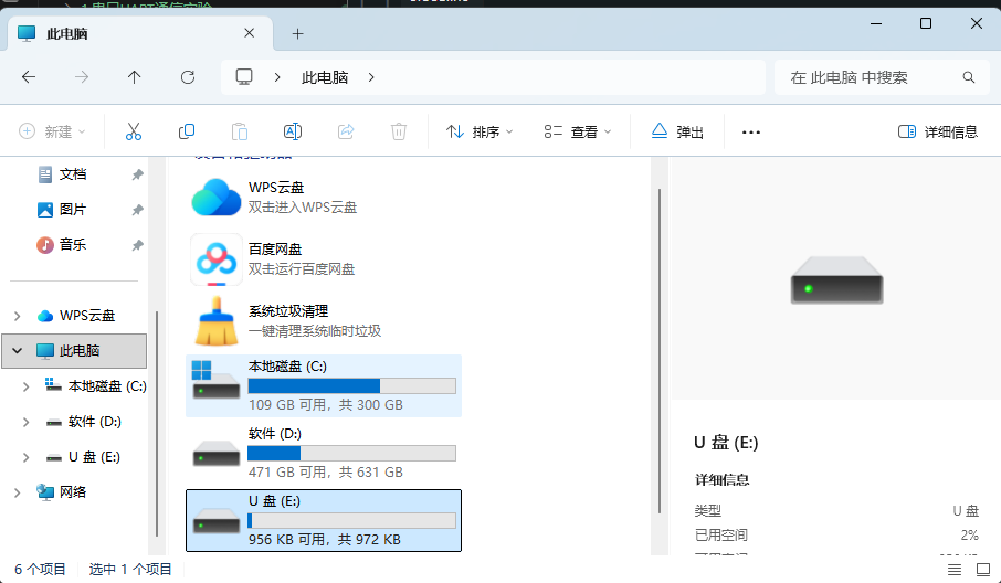
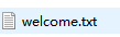
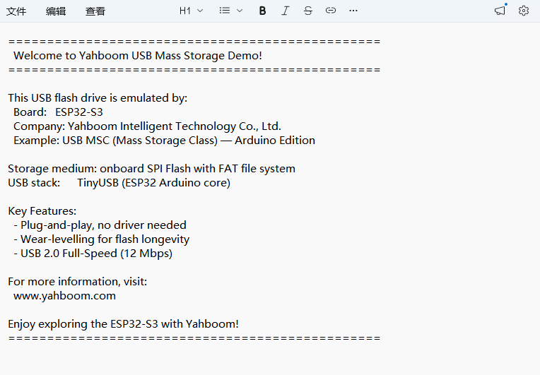
After power-on, PC immediately recognizes it as a FAT-formatted flash drive with a readable/writable welcome.txt file inside.
6.3 Verification Methods
| Operation | Expected Result |
|---|---|
| USB cable connects to PC | PC recognizes as "ESP32-S3 USB MSC" flash drive |
| Open welcome.txt | Shows Yahboom welcome content |
| Create new file on PC side | Writes normally, persists after power cycle |
| Unplug USB cable | Serial prints [USB] UNPLUGGED |
7. Common Issues
| Phenomenon | Cause | Solution |
|---|---|---|
| Plugging USB cable PC has no response | Using USB-UART port instead of native USB port | Switch to native USB port GPIO19/20 |
| PC prompts "Disk needs formatting" | FAT partition not created or corrupted | Check partitions.csv + FFat.begin(true, ...) |
| PC writes file then restart file disappears | onWrite wrote without erasing | Confirm wl_erase_range is before wl_write |
wl_mount fails | WL handle still held by FFat not released | Confirm FFat.end() is before wl_mount |
Serial doesn't print [USB] PLUGGED | USB CDC and MSC share same USB port | Disable USB CDC On Boot, use Serial0 instead |