Welcome to ESP32 Core Board repository
2. Button Detection
Button Detection
Button Detection1. Button Detection Overview2. Core Concepts2.1 Button Bounce and Debouncing2.2 Button Connection and Pull-Up/Pull-Down2.3 Edge Detection Logic2.4 Core API — machine.Pin Input Mode3. Hardware Dependencies4. Project Architecture and Flow5. Source Code Details5.1 Import Modules and Initialization5.2 Main Loop — Polling with Debounce6. Operation Procedure6.1 Flashing and Running6.2 Normal Phenomenon6.3 Verification Methods7. Common Problems
1. Button Detection Overview
GPIO input is the most basic way for an MCU to interact with the outside world. This experiment reads the level of the BOOT button (GPIO0) to control the LED on/off with the button — press once to turn on, press again to turn off. The source code demonstrates the complete flow of GPIO input, software debouncing, edge detection, and a polling architecture.
Typical application scenarios:
| Application Type | Example |
|---|---|
| Digital input | Buttons, DIP switches, door magnet sensors |
| Pulse counting | Rotary encoders, flow meters |
| Status detection | Water level switches, limit switches |
| Wake-up source | Deep Sleep button wake-up |
2. Core Concepts
2.1 Button Bounce and Debouncing
When a mechanical button is pressed/released, the metal contacts bounce repeatedly for 5~20ms, generating a series of glitch pulses:
Ideal waveform: ────┐ ┌────└────────────┘Actual waveform: ────┐ ┌┐ ┌┐ ┌┐ ┌┐ ┌┐ ┌┐ ┌────└┘ └┘ └┘ └┘ └┘ └┘ └┘├─ bounce period ─┤(typically 5~20ms)
Software debouncing: after detecting a level change, wait 20ms before confirming, skipping the bounce region.
2.2 Button Connection and Pull-Up/Pull-Down
The BOOT button on this board has one end connected to GND and the other end directly to GPIO0:
xxxxxxxxxxGND → Button → GPIO0
| Button State | GPIO0 Level | key.value() |
|---|---|---|
| Released | Floating (indeterminate) | Internal pull-up → 1 |
| Pressed | Pulled low to GND | 0 |
Pin.PULL_UPmust be enabled, otherwise the pin floats when released and the level jumps randomly.
2.3 Edge Detection Logic
What is detected is the falling edge from "released" to "pressed":
xxxxxxxxxxif last_key == 1 and current_key == 0: time.sleep_ms(20) # avoid bounce if key.value() == 0: # double-check led.toggle() # toggle LEDlast_key = current_key # must update, otherwise detection fails next timeOnly the falling edge (1→0) is detected to avoid repeated triggering while holding the button.
2.4 Core API — machine.Pin Input Mode
xxxxxxxxxxkey = Pin(0, Pin.IN, Pin.PULL_UP) # input + internal pull-upval = key.value() # read level: 0 or 13. Hardware Dependencies
| GPIO | Peripheral | Mode | Description |
|---|---|---|---|
| 0 | KEY (BOOT) | Pin.IN + Pin.PULL_UP | Pressed=0, released=1 |
| 43 | LED0 | Pin.OUT | Onboard LED, common-anode, 0=on |
The BOOT button is onboard; no external components are required.
4. Project Architecture and Flow
xxxxxxxxxxScript execution (single-file .py)│├─ led = Pin(43, Pin.OUT) // GPIO43 output, on by default (0=on)├─ key = Pin(0, Pin.IN, PULL_UP) // GPIO0 input + pull-up├─ led_state = 0, last_key = 1 // state variable initialization│└─ while True: // polling loop├─ current_key = key.value() // read button├─ if last==1 and cur==0: // falling edge detection│ ├─ sleep_ms(20) // debounce│ ├─ if key.value() == 0: // double-check│ │ ├─ led_state ^= 1 // toggle LED state│ │ └─ led.value(state) // update LED└─ last_key = current_key // update historical state
5. Source Code Details
Full source code: 5.Source Code → MicroPython → 1.Basic Peripherals → 2.KEY_LED → 2.KEY_LED.py
5.1 Import Modules and Initialization
xfrom machine import Pin # Pin class: GPIO controlimport time # delay functions
led = Pin(43, Pin.OUT) # GPIO43 push-pull output, common-anode: 0=on,1=offkey = Pin(0, Pin.IN, Pin.PULL_UP) # GPIO0 input + internal pull-up
led_state = 0 # LED state: 0=on, 1=offlast_key = 1 # last key reading5.2 Main Loop — Polling with Debounce
xxxxxxxxxxwhile True:    current_key = key.value()  # read current key level
    # detect button press: falling edge 1→0, with debounce    if last_key == 1 and current_key == 0:        time.sleep_ms(20)       # 20ms debounce        if key.value() == 0:    # confirm still pressed            led_state = not led_state  # toggle LED            led.value(led_state)       # apply to LED
    last_key = current_key  # save for next iteration
6. Operation Procedure
6.1 Flashing and Running
Thonny IDE steps: See the 1. Before Development → 3.Thonny IDE chapter.
Connect the development board with a USB cable
Select the
ESP32S3interpreter at the bottom right of ThonnyOpen
2. KEY_LED.py→ click the green Run buttonPress the onboard BOOT button and observe the LED
6.2 Normal Phenomenon
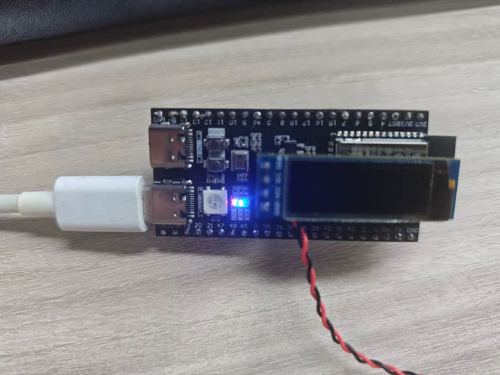
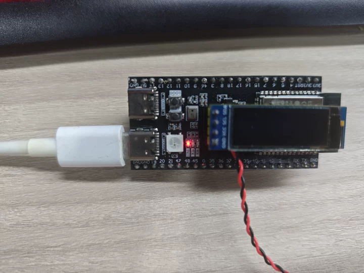
After power-up, the LED is on (
led_state=0,0=on in common-anode)Press BOOT once → LED off
Press again → LED on
A complete trigger is registered only after releasing and pressing again
6.3 Verification Methods
| Operation | Expected Result |
|---|---|
| Power up | LED is on |
| Press BOOT once | LED is off |
| Press again | LED is on |
| Hold the button | LED unchanged (no repeated triggering) |
Change time.sleep_ms(20) to time.sleep_ms(2) | Repeated triggering may occur (insufficient debounce) |
7. Common Problems
| Symptom | Cause | Solution |
|---|---|---|
| Button has no response | Pull_UP not enabled, pin floating | Confirm the Pin.PULL_UP parameter exists |
| Pressing once toggles multiple times | Bounce not eliminated or debounce time too short | Increase the delay in sleep_ms(20) |
| LED keeps toggling while holding the button | Only low level detected, no edge detection | Confirm the last_key == 1 and current_key == 0 logic |
| Multiple presses only respond once | Debounce time too long or poor button contact | Reduce the delay or replace the button |
| BOOT button conflicts with downloading | Holding BOOT during power-up enters download mode | Press it after normal operation; it has no effect |