Welcome to ESP32 Core Board repository
2. Repeater Experiment
Repeater Experiment (MicroPython)
Repeater Experiment (MicroPython)1. Audio Record and Playback All-in-One OverviewAudio Record and Playback All-in-OneApplication ScenariosCore Capabilities2. Core Concepts2.1 I2S Full-Duplex and Time-Division Multiplexing2.2 ES8311 Registers and BOTH Mode2.3 Pop Suppression Mechanism2.4 Streaming WAV File Storage2.5 WAV File Format3. Project Architecture and Flow3.1 Recording Data Flow3.2 Playback Data Flow4. Hardware Connection5. Source Code Details5.1 File Structure5.2 es8311.py — Codec Driver5.2.1 Macro Configuration5.2.2 Register Operations5.2.3 init() — Initialization Flow5.2.4 Key Register Quick Reference5.2.5 Interface API5.2.6 TX/RX Mode Switching5.3 wav.py — Streaming WAV Read/Write5.3.1 Macro Configuration5.3.2 Streaming Write5.3.3 Streaming Read5.4 led.py — WS2812 RGB LED5.5 main.py — Main Program5.5.1 Macro Configuration5.5.2 Global State5.5.3 Helper Functions5.5.4 Button State Machine5.5.5 Playback Thread5.5.6 Recording Thread6. Operating Procedure6.1 File Upload6.2 Start and Run6.3 Normal Operation Demo6.4 Edge Cases7. FAQ8. Parameter Tuning Guide8.1 Changing the Volume8.2 Changing the Microphone Gain8.3 Changing the Sample Rate8.4 Changing the Maximum Recording Duration
1. Audio Record and Playback All-in-One Overview
Audio Record and Playback All-in-One
In embedded audio development, implementing both recording and playback is a key advanced milestone. Playback or recording alone only requires I2S half-duplex mode, while record and playback all-in-one requires the I2S bus to drive the ADC and DAC on a time-shared basis, and to properly manage the timing and resource sharing of both.
MicroPython's machine.I2S does not support simultaneous TX and RX operations on the same port, so a dynamic TX/RX mode switch must be implemented at the software level. In addition, the ESP32-S3 MicroPython heap cannot allocate a 640KB contiguous recording buffer, so streaming WAV file read/write must be used to circumvent the memory limitation.
This tutorial fully implements a button-driven audio record and playback all-in-one machine, including pop suppression, streaming WAV storage, rainbow LED effects, and a full set of features.
Application Scenarios
- Smart voice assistant: record samples → speech recognition → speech synthesis announcement
- Walkie-talkie / access control system: press and hold to talk (record) → release the button (play response)
- Audio memo / message machine: long press to record, short press to play back
- Educational toys / learning machines: repeat-after-me recording → playback comparison
- IoT voice alarm: event-triggered pre-recorded voice, played locally immediately
Core Capabilities
| Function | Description |
|---|---|
| Recording | ES8311 ADC, 16kHz / 16-bit / mono, up to 20 seconds, streaming write to file |
| Playback | ES8311 DAC, 16kHz / 16-bit / stereo (mono duplicated to L+R), streaming read from file |
| Button logic | BOOT button (GPIO0): long press + hold = record, release = stop; short press = play/pause/resume |
| LED feedback | WS2812 RGB LED: green while recording, red when recording complete, rainbow hue animation while playing |
| Pop suppression | DAC hardware mute → minimum gain → mute flush → amplifier on; restore gain and unmute before playback |
| MCLK generation | PWM (LEDC) outputs 4.096MHz to GPIO15 |
2. Core Concepts
2.1 I2S Full-Duplex and Time-Division Multiplexing
The I2S bus contains four signal lines: MCLK (master clock), BCLK (bit clock), WS (frame clock / LRCK), and DATA. Full-duplex means simultaneous transmission and reception, requiring two data lines — DOUT (TX, ESP32 → DAC) and DIN (RX, ADC → ESP32) — sharing the MCLK/BCLK/WS clocks.
xxxxxxxxxxMCLK (GPIO15, PWM 4.096MHz) / Master clockESP32 ──────────────────────────────→ ES8311BCLK (GPIO16, 512kHz) / Bit clockESP32 ──────────────────────────────→ ES8311WS (GPIO18, 16kHz) / Frame clockESP32 ──────────────────────────────→ ES8311DOUT (GPIO8) / Playback dataESP32 ──────────────────────────────→ ES8311 SDIN (DAC)DIN (GPIO17) / Recording dataESP32 ←────────────────────────────── ES8311 SDOUT (ADC)I2C (GPIO41/42) / Control interfaceESP32 ←─────────────────────────────→ ES8311
A MicroPython I2S object can only be either TX or RX at any given time, not both simultaneously. Therefore:
- While playing: I2S is initialized in TX mode, continuously outputting silence frames to maintain the clock
- While recording:
deinit()TX → create RX → after recording finishes →deinit()RX → recreate TX
The switch takes <10ms, which has no impact on button responsiveness.
2.2 ES8311 Registers and BOTH Mode
The ES8311 is configured via I2C (address 0x18). BOTH mode means the ADC and DAC are enabled simultaneously; this project completes the configuration by writing registers directly through I2C.
| Parameter | Value |
|---|---|
| Operating mode | ADC + DAC (BOTH) |
| MCLK | 4.096 MHz (generated by PWM, 256×Fs) |
| Sample rate | 16000 Hz |
| Bit depth | 16-bit |
| Channels | Stereo slots (mono data duplicated to L+R) |
| MIC gain | 24 dB (adjustable 0~42dB, 6dB per step) |
2.3 Pop Suppression Mechanism
At power-on, improper startup timing of the ES8311 DAC and NS4150 amplifier can produce a "pop" sound. This project adopts a six-stage suppression strategy:
xxxxxxxxxxStage 1: DAC mute — REG31 bits[6:5]=11, hardware-level cutoff of DAC outputStage 2: Analog path on — REG0E=0x02, VMID reference voltage establishedStage 3: Set minimum gain — REG32=0x00, lowest DAC volumeStage 4: Mute flush — write ~1 second of zero PCM to I2S TX to flush residual noiseStage 5: Amplifier on — PA=on, wait 100ms to stabilizeStage 6: Stay muted — DAC remains muted, waiting for the playback command
The restore flow when playback starts:
xBefore playback:① dac_vol(90) → set target volume (REG32)② dac_mute(False) → unmute hardware (REG31)③ sleep_ms(10) → wait for the register to take effect④ i2s.write(1024B silence) → leading buffer, ensure a clean startAfter playback:① i2s.write(1024B silence) → trailing buffer, flush residual pipeline data② dac_mute(True) → mute the DAC again
When pausing, only the mute register is controlled; the I2S and audio data stream are left untouched. The following code implements hardware-level mute switching by setting the mute bit of REG31, which is cleaner and has no latency compared to stopping the I2S data stream:
xxxxxxxxxx# Pause — mute immediatelydac_mute(True)# Resume — unmute firstdac_mute(False)2.4 Streaming WAV File Storage
A WAV file = 44-byte header + PCM data. The technical difficulty is that the file size is unknown during recording, while the RIFF size and data size fields in the WAV header require exact values.
Solution — placeholder header + trailing correction:
The following code shows the complete streaming recording flow — write a placeholder header first, append PCM chunk by chunk in a loop, and finally call finalize_write to seek back to the file header and correct the actual data size:
xxxxxxxxxx# Recording start: write placeholder header (size fields filled with max possible value 0x7FFFFFFF)f = wav.open_write("/record.wav")# Recording loop: append PCM chunkswhile recording: f.write(mono_chunk) # ~1KB each write, tiny footprint# Recording end: seek back, patch headerwav.finalize_write(f) # seek(4) to patch RIFF size → seek(40) to patch data sizeThe playback side also processes streaming and does not load all audio at once. open_read parses the RIFF chunk and returns the file handle and data area offset; the caller reads chunk by chunk → converts → writes I2S:
xxxxxxxxxx# Open file, parse header, get data offset and sizef, rate, ch, bits, data_offset, data_bytes = wav.open_read("/record.wav")# Read in chunks, push to I2Sf.seek(data_offset)while remaining > 0: n = f.readinto(mono_buf) # read ~1KB each i2s.write(mono_to_stereo(buf)) # mono→stereo→write I2SThe streaming scheme's maximum memory usage is only ~6KB (a few 2KB buffers), completely solving the problem of the MicroPython heap being unable to allocate 640KB. Recording duration is limited only by the remaining Flash space.
2.5 WAV File Format
| Offset | Size | Field | Value (this project) |
|---|---|---|---|
| 0 | 4 | RIFF identifier | "RIFF" |
| 4 | 4 | File size - 8 | uint32 LE |
| 8 | 4 | WAVE identifier | "WAVE" |
| 12 | 4 | fmt identifier | "fmt " |
| 16 | 4 | Format chunk size | 16 (PCM) |
| 20 | 2 | Audio format | 1 (PCM) |
| 22 | 2 | Number of channels | 1 (mono) |
| 24 | 4 | Sample rate | 16000 |
| 28 | 4 | Byte rate | 32000 |
| 32 | 2 | Block alignment | 2 |
| 34 | 2 | Bit depth | 16 |
| 36 | 4 | data identifier | "data" |
| 40 | 4 | Data size | uint32 LE |
| 44 | N | PCM data | int16 LE |
3. Project Architecture and Flow
xxxxxxxxxxmain()├─ es8311.init() ← audio chain initialization│ ├─ PA pin pulled low (amplifier off)│ ├─ PWM outputs 4.096MHz MCLK (GPIO15, 50% duty cycle)│ ├─ I2C bus + device scan (confirm 0x18)│ ├─ I2S TX started first (generates BCLK=512kHz + WS=16kHz)│ ├─ register baseline config — clock, OSR, mic gain│ ├─ clock divider — MCLK÷1, BCLK÷4, LRCK÷256│ ├─ I2S format + bit depth — standard I2S, 16-bit│ ├─ enable ADC+DAC — power up analog/digital│ └─ pop suppression — mute→min gain→mute flush→PA on│├─ led.init() ← WS2812 initialization and light off└─ btn_task() ← button polling (main loop, ~50Hz)btn_task (main loop):while True:Detect BOOT button (GPIO0, active low)Debounce 30ms│├─ Long press (≥800ms) → recording flow:│ 1. Set g_rec = True│ 2. _thread starts record_task()│ 3. Wait for release (while button not released)│ 4. Set g_rec = False│ 5. Wait for the recording thread to exit│└─ Short press (<800ms) → playback flow:1. Playing and paused → resume (dac_mute(False))2. Playing and not paused → pause (dac_mute(True))3. Idle → play_start(REC_FILE)record_task (independent thread):wav.open_write() → i2s_rx()while g_rec:rx.readinto(rx_buf) → read interleaved stereo data_rx_left(rx_buf) → extract left channelf.write(mono_chunk) → streaming append writeend: wav.finalize_write(f) → i2s_tx() restore TXplay_file (independent thread):wav.open_read() → dac_vol() → dac_mute(False)while data available:f.readinto(mono_buf) → streaming read_m2s(mono_buf) → mono→stereo duplicationi2s.write(stereo_buf) → write I2Swhen paused: while g_pause: sleepend: silence buffer → dac_mute(True)
3.1 Recording Data Flow
xxxxxxxxxxES8311 ADC → I2S DIN (GPIO17) → i2s.readinto(rx_buf)→ interleaved stereo {L0,R0, L1,R1, L2,R2, ...}→ extract left channel {L0, L1, L2, ...}, discard right channel→ f.write(mono_chunk)→ /record.wav (streaming append)
3.2 Playback Data Flow
xxxxxxxxxx/record.wav → wav.open_read() → f.readinto(mono_buf)→ mono {M0, M1, M2, ...}→ duplicate to stereo {M0,M0, M1,M1, M2,M2, ...}→ i2s.write(stereo_buf)→ I2S DOUT (GPIO8) → ES8311 DAC → NS4150 PA → speaker
4. Hardware Connection
| Pin | Function | Connection Target |
|---|---|---|
| GPIO42 | I2C SCL | ES8311 SCL |
| GPIO41 | I2C SDA | ES8311 SDA |
| GPIO15 | MCLK | ES8311 MCLK (PWM output 4.096MHz) |
| GPIO16 | I2S BCLK | ES8311 BCLK |
| GPIO18 | I2S WS | ES8311 LRCK (frame clock) |
| GPIO8 | I2S DOUT | ES8311 SDIN (DAC data input) |
| GPIO17 | I2S DIN | ES8311 SDOUT (ADC data output) |
| GPIO7 | PA_EN | NS4150 amplifier enable (active high) |
| GPIO48 | WS2812 Data | RGB LED data input |
| GPIO0 | BOOT button | Active low, internal pull-up |
Core devices:
| Device | Model | Communication Interface | Address/Pin |
|---|---|---|---|
| MCU | ESP32-S3 | — | — |
| Audio codec | ES8311 | I2C + I2S | I2C address 0x18 |
| Amplifier | NS4150 | GPIO control | GPIO7 (enable high) |
| RGB LED | WS2812 | Single-wire | GPIO48 |
5. Source Code Details
5.1 File Structure
Complete source code: 5.Source Code Collection → MicroPython → 5.Aduio → 2.Audio_Play_Record → main.py
xxxxxxxxxxRPR/├── es8311.py # ES8311 codec driver├── wav.py # streaming WAV I/O├── led.py # WS2812 RGB LED control└── main.py # main program
5.2 es8311.py — Codec Driver
5.2.1 Macro Configuration
All hardware pins and audio parameters are centrally managed at the top of the file; modifying one line adapts to different hardware layouts:
xxxxxxxxxx# ====== Config ======SCL=42; SDA=41; PA=7; ADDR=0x18 # I2C + PASCK=16; WS=18; DOUT=8; DIN=17 # I2S pinsMCLK_PIN=15; RATE=16000; MIC=24 # Audio| Macro | Value | Description |
|---|---|---|
RATE | 16000 | Sample rate / Hz |
MIC | 24 | Microphone gain / dB, options 0/6/12/18/24/30/36/42 |
MCLK_PIN | 15 | MCLK output pin, PWM generates 4.096MHz |
ADDR | 0x18 | ES8311 7-bit I2C device address |
5.2.2 Register Operations
The ES8311 registers are read and written directly via I2C. Two one-line functions wrap MicroPython's writeto_mem / readfrom_mem; all subsequent register operations go through them:
xxxxxxxxxxdef W(reg, val): """Write register""" _i2c.writeto_mem(ADDR, reg, bytes([val]))def R(reg): """Read register""" return _i2c.readfrom_mem(ADDR, reg, 1)[0]5.2.3 init() — Initialization Flow
init() is the entry point of the audio chain and the core of the ES8311 driver. It executes strictly in order: first establish the MCLK clock → start the I2S bus to generate BCLK+WS → configure the ES8311 registers → perform pop suppression.
Step 1: Hardware Preparation
The following code completes three basic hardware initializations — PA pin pulled low to prevent power-on pops, PWM outputs the 4.096MHz master clock, I2C bus ready:
xxxxxxxxxx# PA off initially to avoid pop_pa = Pin(PA, Pin.OUT, value=0)# MCLK — PWM outputs 4.096MHz_mclk = PWM(Pin(MCLK_PIN), freq=4096000, duty=512) # 50% duty# I2C bus_i2c = I2C(0, scl=Pin(SCL), sda=Pin(SDA), freq=100000)Why can PWM be used as MCLK? The MCLK input of the ES8311 only needs a stable square wave clock, and the square wave output by PWM at high frequency fully meets the requirement. The key is to ensure the frequency is accurate: MCLK = sample rate × 256 = 16000 × 256 = 4,096,000 Hz.
Step 2: I2S Started Before ES8311
Before configuring the ES8311 registers, the I2S master mode must first generate the BCLK and WS clock signals, and write silence data to stabilize the I2S state machine:
xxxxxxxxxx# I2S master mode — generates BCLK+WS_i2s = I2S(0, sck=Pin(SCK), ws=Pin(WS), sd=Pin(DOUT), mode=I2S.TX, bits=16, format=I2S.STEREO, rate=RATE, ibuf=11520)_i2s.write(bytearray(1024)) # flood silence to stabilizeWhy start I2S before ES8311? As a slave device, the ES8311's internal state machine needs the BCLK and WS clock signals to latch the register configuration. If the registers are written first and I2S is started afterwards, the register values may not be loaded correctly into the shadow registers.
Step 3: Register Baseline Configuration
The following code writes the register groups necessary for ES8311 power-on initialization — system power mode, GPIO noise immunity, clock disable, oversampling rate, microphone gain, and CSM reset:
xxxxxxxxxxW(0x0D, 0xFA) # System power-downW(0x44, 0x08); W(0x44, 0x08) # GPIO noise immunity (written twice)W(0x01, 0x30) # Clocks disabledW(0x02, 0x00); W(0x03, 0x10); W(0x04, 0x10); W(0x05, 0x00)W(0x16, MIC_GAIN_REG_VAL) # Mic gainW(0x0B, 0x00); W(0x0C, 0x00)W(0x10, 0x1F); W(0x11, 0x7F)W(0x00, 0x80) # CSM + clock manager resetStep 4: Clock Source Selection
Set the MCLK pin as the clock source (not the internal oscillator), non-inverted, enable all clock modules, and establish the internal reference loop:
xxxxxxxxxxW(0x01, 0x3F) # MCLK pin, non-inverted, all clocks onW(0x06, R(0x06) & ~0x20) # SCLK non-invertedW(0x13, 0x10); W(0x1B, 0x0A); W(0x1C, 0x6A)W(0x44, 0x58) # Internal reference ADCL+DACRStep 5: Clock Divider Configuration (16kHz)
For MCLK=4.096MHz and a target sample rate of 16kHz, configure the pre-divider, multiplier, ADC/DAC oversampling rates, and LRCK/BCLK division ratios:
xxxxxxxxxx# pre=1, multi=1xW(0x02, (R(0x02) & 0x07) | (0<<5) | (0<<3))# adc/div=1, dac/div=1W(0x05, 0x00)# ADC OSR=0x10, DAC OSR=0x20W(0x03, (R(0x03) & 0x80) | (0<<6) | 0x10)W(0x04, (R(0x04) & 0x80) | 0x20)# LRCK divider: H=0x00, L=0xFFW(0x07, (R(0x07) & 0xC0) | 0x00)W(0x08, 0xFF)# BCLK div=4W(0x06, (R(0x06) & 0xE0) | 3)Step 6: I2S Format and Bit Depth
Configure the ES8311 serial data port (SDP) to the standard I2S format + 16-bit bit depth, aligned with the ESP32-side I2S parameters:
xxxxxxxxxx# I2S standard format (bits[1:0]=00)W(0x09, R(0x09) & 0xFC)W(0x0A, R(0x0A) & 0xFC)# 16-bit depth (bits[3:2]=11)W(0x09, R(0x09) | 0x0C)W(0x0A, R(0x0A) | 0x0C)Step 7: Enable ADC+DAC
Set slave mode, clear the data path tri-state gates, BOTH mode configuration, analog/digital power up, and ADC/DAC ramp rates:
xxxxxxxxxxW(0x00, 0x80) # Slave modeW(0x01, 0x3F) # MCLK pin, all clocks on# Enable data paths (clear tri-state bit6)v9 = R(0x09) & 0xBF; vA = R(0x0A) & 0xBFv9 &= 0xC0; vA &= 0xC0 # BOTH mode: clear bits[5:0]W(0x09, v9); W(0x0A, vA)# Power up analog+digitalW(0x17, 0xBF); W(0x0E, 0x02); W(0x12, 0x00); W(0x14, 0x1A)W(0x14, R(0x14) & ~0x40) # Analog mic (not PDM DMIC)W(0x0D, 0x01) # Power up!W(0x15, 0x40); W(0x37, 0x08); W(0x45, 0x00)Step 8: Pop Suppression
DAC mute → minimum volume → 1 second silence flush through the I2S pipeline → amplifier on (DAC stays muted), completing the six-stage pop suppression:
xxxxxxxxxxdac_mute(True) # DAC mute (REG31 bits[6:5]=11)W(0x32, 0x00) # Min volume (REG32=0x00)# ~1s silence flush to purge the I2S pipelinezz = bytearray(12800)_i2s.write(zz)# PA on (DAC stays muted)_pa.on()5.2.4 Key Register Quick Reference
| Register | Name | Function | Typical Value |
|---|---|---|---|
| 0x00 | RESET | Reset and master/slave mode | 0x80 (slave mode) |
| 0x01 | CLK_MANAGER1 | MCLK source selection (bit7) + clock enable (bits[5:0]) | 0x3F (MCLK pin, all clocks on) |
| 0x02 | CLK_MANAGER2 | Pre-divider (bits[7:5]) + multiplier (bits[4:3]) | pre=1, multi=1x |
| 0x03 | CLK_MANAGER3 | ADC fs_mode (bit6) + ADC OSR (bits[4:0]) | OSR=0x10 |
| 0x04 | CLK_MANAGER4 | DAC OSR (bits[4:0]) | OSR=0x20 |
| 0x06 | CLK_MANAGER6 | BCLK inversion (bit5) + BCLK division (bits[4:0]) | BCLK÷4 |
| 0x07 | CLK_MANAGER7 | LRCK divider high byte | 0x00 |
| 0x08 | CLK_MANAGER8 | LRCK divider low byte | 0xFF |
| 0x09 | SDPIN | DAC I2S format (bits[1:0]) + bit depth (bits[3:2]) + tri-state (bit6) | I2S + 16-bit |
| 0x0A | SDPOUT | ADC I2S format + bit depth | Same as 0x09 |
| 0x0D | SYSTEM0D | System power up/down | 0x01=power up, 0xFA=power down |
| 0x0E | SYSTEM0E | Analog power (VMID reference) | 0x02 |
| 0x12 | SYSTEM12 | DAC path enable | 0x00=enabled |
| 0x16 | ADC16 | Microphone gain | 0–7 (6dB per step) |
| 0x31 | DAC31 | DAC mute bits[6:5] | 0x60=muted, 0x00=normal |
| 0x32 | DAC32 | DAC volume | 0x00=min, 0xFF=max |
5.2.5 Interface API
| Function | Description |
|---|---|
init() | Initialize the audio chain (MCLK→I2C→I2S→ES8311→pop suppression) |
dac_mute(m) | Control DAC mute (True=muted, False=normal) |
dac_vol(p) | Set DAC volume 0–100 (percentage) |
pa_ctrl(on) | Control amplifier enable |
i2s() | Get the current I2S handle (shared for playback) |
i2s_rx() | Switch I2S to RX mode (call before recording) |
i2s_tx() | Switch I2S to TX mode (call after recording) |
dump() | Print all register values (for debugging) |
5.2.6 TX/RX Mode Switching
Since MicroPython I2S does not support simultaneous TX+RX, mode switching uses deinit → recreate: first close the current I2S instance, then recreate it in the target mode. Writing silence data after switching accelerates clock stabilization:
xxxxxxxxxxdef i2s_rx(): """Switch I2S to RX for recording""" global _i2s if _i2s: _i2s.deinit() # deinit TX first _i2s = I2S(0, ..., mode=I2S.RX, ...) return _i2sdef i2s_tx(): """Switch back to TX for playback""" global _i2s if _i2s: _i2s.deinit() # deinit RX first _i2s = I2S(0, ..., mode=I2S.TX, ...) _i2s.write(bytearray(1024)) # stabilize clocks return _i2sCall
i2s_rx()at the start of recording, and calli2s_tx()in thefinallyblock after recording to restore, ensuring the TX mode is restored even in exceptional situations.
5.3 wav.py — Streaming WAV Read/Write
5.3.1 Macro Configuration
The top of the file defines the audio format parameters of the WAV file; these values determine the calculation results of each header field:
xxxxxxxxxxSAMPLE_RATE = 16000 # Sample rateBIT_DEPTH = 16 # Bits per sampleCHANNELS = 1 # Mono storageHEADER_SIZE = 44 # Fixed header size5.3.2 Streaming Write
open_write() first writes a placeholder header (RIFF size filled with the maximum possible value 0x7FFFFFFF), and finalize_write() precisely corrects the two size fields by Seek after recording finishes:
xxxxxxxxxxdef open_write(filename): """Open WAV with placeholder header""" f = open(filename, 'wb') f.write(_build_header(0x7FFFFFFF)) # placeholder return fdef finalize_write(f): """Patch header with actual size, then close""" actual_size = f.tell() - HEADER_SIZE f.seek(4) # RIFF size field f.write(struct.pack('<I', actual_size + 36)) # patch RIFF size f.seek(40) # data size field f.write(struct.pack('<I', actual_size)) # patch data size f.close()5.3.3 Streaming Read
open_read() validates the RIFF/WAVE magic numbers, then iterates the chunks to locate the fmt chunk and parse the audio parameters, and locates the data chunk to obtain the data offset and size, returning the file handle for the caller to read chunk by chunk:
xxxxxxxxxxdef open_read(filename): """Open WAV for streaming read""" f = open(filename, 'rb') # Validate RIFF magic if f.read(4) != b'RIFF': return None f.read(4) # skip file size if f.read(4) != b'WAVE': return None # validate WAVE # Parse chunks, locate fmt and data while True: cid = f.read(4) csize = struct.unpack('<I', f.read(4))[0] if cid == b'fmt ': # format chunk fmt_data = f.read(csize) # parse rate, channels, bits elif cid == b'data': # data chunk # record offset and size return f, rate, channels, bits, f.tell(), csize else: f.read(csize) # skip unknown5.4 led.py — WS2812 RGB LED
Based on MicroPython's built-in neopixel library, it controls one WS2812 LED. The following code imports the dependency and creates the NeoPixel instance; all subsequent color control is done through _NP[0] = (g, r, b):
xxxxxxxxxxfrom machine import Pinfrom neopixel import NeoPixelLED_PIN = 48 # data pin_NP = NeoPixel(Pin(LED_PIN), 1)| Function | Description |
|---|---|
init() | Initialize NeoPixel and turn off |
set_color(g, r, b) | Set GRB color (0–255) |
off() | Turn off |
rainbow_step() | Advance rainbow hue one step (~1.4°) |
Rainbow algorithm: The hue space 0–65535 is divided into 6 sectors (R→Y→G→C→B→M→R), advancing 400 units per step (about 1.4°). In the playback loop, it is called once per frame (about every 32ms), producing a smooth gradient effect.
The following code decomposes the hue into a sector number and a blend factor, calculates the current RGB through 6-segment linear interpolation, writes it to the NeoPixel, and then advances the hue counter:
xxxxxxxxxxdef rainbow_step(): """Advance rainbow hue one step""" global _hue sector = (_hue >> 13) & 0x7 # hue sector x = (_hue >> 5) & 0xFF # blend factor if sector == 0: r, g, b = 255, x, 0 # Red→Yellow elif sector == 1: r, g, b = 255 - x, 255, 0 # Yellow→Green elif sector == 2: r, g, b = 0, 255, x # Green→Cyan elif sector == 3: r, g, b = 0, 255 - x, 255 # Cyan→Blue elif sector == 4: r, g, b = x, 0, 255 # Blue→Magenta else: r, g, b = 255, 0, 255 - x # Magenta→Red _NP[0] = (g, r, b) # WS2812 GRB wire order _NP.write() _hue = (_hue + 400) & 0xFFFF # advance, wrap at 360°5.5 main.py — Main Program
5.5.1 Macro Configuration
The top of the main program centrally defines all adjustable parameters — sample rate, volume, recording duration, button thresholds, file paths, etc.; modifying one line takes effect globally:
xxxxxxxxxx# ====== Config ======RATE=16000; # Sample rateVOL=90; # Playback volume (%)REC_SEC=20; # Max record duration (s)CHUNK=512; # Samples per I2S writeRXSZ=1920 # RX read frame sizeBTN=0; # Button pinDB=30; # Debounce time (ms)LONG=800 # Long press threshold (ms)REC_FILE="/record.wav" # Record output file| Macro | Value | Description |
|---|---|---|
RATE | 16000 | Sample rate (must be consistent with es8311.py) |
VOL | 90 | Playback volume percentage |
REC_SEC | 20 | Max recording duration / seconds |
CHUNK | 512 | Samples per I2S write |
RXSZ | 1920 | RX read frame size (aligned with DMA) |
BTN | 0 | BOOT button GPIO |
DB | 30 | Debounce time / ms |
LONG | 800 | Long press threshold / ms |
5.5.2 Global State
Three boolean flags form a simple state machine. The button logic polls on the main thread, recording/playback run on independent threads, and the three coordinate their behavior by reading and writing these global variables (boolean reads/writes are atomic in MicroPython _thread):
xxxxxxxxxxg_rec = False # recording in progressg_play = False # playback in progressg_pause = False # playback paused5.5.3 Helper Functions
Stereo extraction (recording) — I2S RX returns interleaved stereo data {L0,R0, L1,R1, ...}; the following code processes pairs of 4 bytes, extracting the first 2 bytes (left channel) of each pair and discarding the right channel:
xxxxxxxxxxdef _rx_left(rx, nb): """I2S stereo RX → left-mono bytes""" np = nb // 4 m = bytearray(np * 2) for i in range(np): m[i*2] = rx[i*4] # left low byte m[i*2+1] = rx[i*4+1] # left high byte return mThe ES8311 MIC signal appears on the left channel slot; the right channel is silence or noise and is directly discarded.
Mono to stereo (playback) — each 16-bit sample of the mono file is duplicated to the right channel, forming the interleaved stereo format {M0,M0, M1,M1, ...}:
xxxxxxxxxxdef _m2s(m, n): """n mono samples → stereo bytes""" o = bytearray(n * 4) for i in range(n): lo, hi = m[i*2], m[i*2+1] o[i*4]=lo; o[i*4+1]=hi; o[i*4+2]=lo; o[i*4+3]=hi # L then R return oThe ES8311 I2S slot is stereo; a mono file must be duplicated to the L+R slots for correct output.
5.5.4 Button State Machine
The button uses polling (~50Hz) and does not rely on interrupts. The following code first debounces for 30ms, then measures the hold duration — ≥800ms is judged as a long press (recording), otherwise a short press (play/pause/resume), while also checking the current state to avoid conflicts:
xxxxxxxxxxdef btn_task(): """Button monitor: long press→record, short press→play/pause/resume""" b = Pin(BTN_PIN, Pin.IN, Pin.PULL_UP) # active-low, pull-up while True: if b.value() == 0: # button pressed time.sleep_ms(DB) # debounce if b.value(): continue # debounce failed hold = 0 while b.value() == 0: # measure hold duration time.sleep_ms(50); hold += 50 if hold >= LONG: break if hold >= LONG: # long press→record print("main: long press -> start recording (hold to keep)") record_start() while b.value() == 0: time.sleep_ms(50) # wait release print("main: button released -> stop recording") record_stop() else: # short press→play/pause/resume if g_play and g_pause: print("main: short press -> resume") es8311.dac_mute(False); g_pause = False elif g_play: print("main: short press -> pause") es8311.dac_mute(True); g_pause = True else: print("main: short press -> play") play_start(REC_FILE)Button Behavior Table:
| Action | Current State | Result |
|---|---|---|
| Long press + hold (>800ms) | Idle | Start recording (LED green) |
| Release button | Recording | Stop recording, save file (LED red) |
| Short press | Idle | Play the recording file (LED rainbow) |
| Short press | Playing | Pause (DAC muted, LED stops changing color) |
| Short press | Paused | Resume playback (DAC unmuted, LED rainbow again) |
5.5.5 Playback Thread
The following code fully shows the playback thread flow — open WAV and parse header, set volume and unmute, leading silence to prevent pops, main loop reads file chunk by chunk → mono to stereo → write I2S, trailing silence → mute again. The finally block ensures resource cleanup on exceptions:
xxxxxxxxxxdef play_file(path): """Stream WAV file → I2S TX""" r = wav.open_read(path) f, rate, ch, bits, off, nb = r i2s = es8311.i2s() es8311.dac_vol(VOL) # set volume es8311.dac_mute(False) # unmute i2s.write(bytearray(1024)) # pop-free cushion f.seek(off) mono = bytearray(CHUNK * 2) remaining = nb while remaining > 0: while g_pause: # pause gate time.sleep_ms(50) n = f.readinto(memoryview(mono)[:min(len(mono), remaining)]) if n <= 0: break remaining -= n i2s.write(_m2s(mono, n // 2)) led.rainbow_step() # rainbow animation i2s.write(bytearray(1024)) # pop-free end es8311.dac_mute(True) # re-mutePlayback flow diagram:
xxxxxxxxxxOpen WAV → parse header→ dac_vol(90) set volume→ dac_mute(False) unmute→ silence buffer (1024B) leading, prevent pops→ while data:│ ├─ f.readinto(mono) streaming read│ ├─ mono→stereo duplicate to L+R│ └─ i2s.write(stereo) write I2S→ silence buffer (1024B) trailing, flush pipeline→ dac_mute(True) re-mute
5.5.6 Recording Thread
The following code fully shows the recording thread flow — open WAV and write placeholder header, switch I2S to RX, main loop reads stereo → extracts left channel → streaming append write, and the finally block corrects the WAV header and restores TX mode:
xxxxxxxxxxdef record_task(): """Stream I2S RX → WAV file""" print("rec: started"); led.set_color(0, 255, 0) # green=recording f = wav.open_write(REC_FILE) # open with placeholder header rx = es8311.i2s_rx() # switch to RX rbuf = bytearray(RXSZ) t0 = time.ticks_ms() while g_rec: if time.ticks_diff(time.ticks_ms(), t0) // 1000 >= REC_SEC: print(f"rec: max duration ({REC_SEC}s)") break # auto-stop on timeout nb = rx.readinto(rbuf) if nb <= 0: continue mono = _rx_left(rbuf, nb) # extract left channel f.write(mono) # streaming append # finally ensures cleanup g_rec = False wav.finalize_write(f) # patch header + close es8311.i2s_tx() # restore TX led.set_color(255, 0, 0) # red=save doneRecording flow diagram:
xxxxxxxxxxOpen WAV (placeholder header)→ i2s_rx() switch to RX mode→ while g_rec:│ ├─ rx.readinto(rbuf) read stereo from I2S│ ├─ _rx_left(rbuf) extract left│ └─ f.write(mono) append to file→ timeout or button release→ wav.finalize_write(f) seek back patch header→ i2s_tx() restore TX mode
6. Operating Procedure
6.1 File Upload
Upload the 4 .py files to the /RPR/ directory on the ESP32-S3 Flash:
xxxxxxxxxxFlash /└── RPR/├── es8311.py # ES8311 codec driver├── wav.py # streaming WAV I/O├── led.py # WS2812 LED control└── main.py # main program
Use Thonny IDE's file manager to upload. For detailed steps, see the "Environment Setup" chapter:
MicroPython → 1. Before Development → 1.Environment Setup → Environment Setup
6.2 Start and Run
Manual start (serial REPL):
xxxxxxxxxxfrom RPR.main import mainmain()Auto start (write boot.py):
Write the following code into boot.py on the Flash root directory. When the ESP32-S3 powers on, the MicroPython firmware will automatically execute it, without the need to manually enter REPL commands:
xxxxxxxxxx# boot.py — auto-run on bootfrom RPR.main import mainmain()6.3 Normal Operation Demo
Step 1: Confirm the hardware connection
This development board has the ES8311 audio codec chip, NS4150 amplifier, and WS2812 RGB LED on board, with no external modules required. Ensure the speaker is connected to the amplifier output; it is ready to use after power-on.
Step 2: Power-on reset, observe the serial output
xxxxxxxxxxMPY: soft reboot=== Audio Player/Recorder ===I2C: ['0x18']ES8311 OK — MCLK=PWM, PA=ON, DAC=MUTED, REG32=0x00led: init GPIO48main: ready — long press+hold=record | short press=play/pause/resume
If the I2C scan does not show
0x18, the ES8311 communication is abnormal. Check the SCL(42)/SDA(41) wiring and ES8311 power supply.

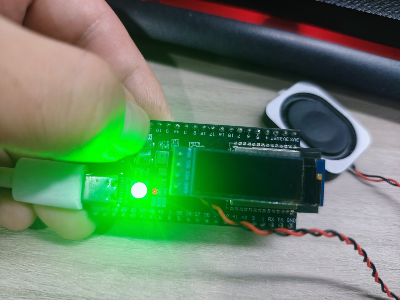
Step 3: Long press and hold the BOOT button (>0.8s) to start recording
xxxxxxxxxxmain: long press -> start recording (hold to keep)rec: started
The LED lights up green, indicating recording is in progress. Speak into the on-board MIC.
Step 4: Release the BOOT button to stop recording
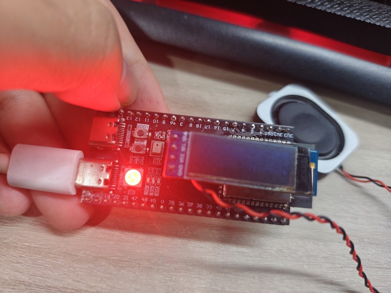
xxxxxxxxxxmain: button released -> stop recordingwav: finalized 72960 bytes PCMrec: done — 72960bytes saved
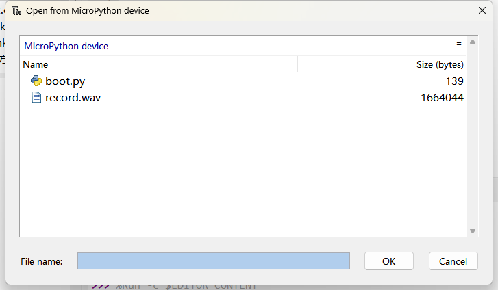
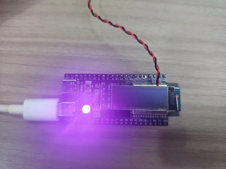
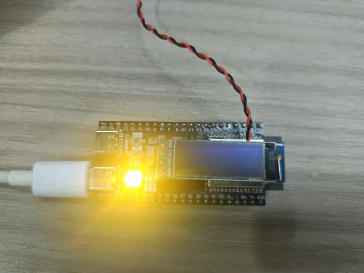
The LED turns red (briefly ~200ms), then turns off. The recording is saved to Flash in WAV format.
Save to Flash:
Step 5: Short press the BOOT button to play the just-recorded audio
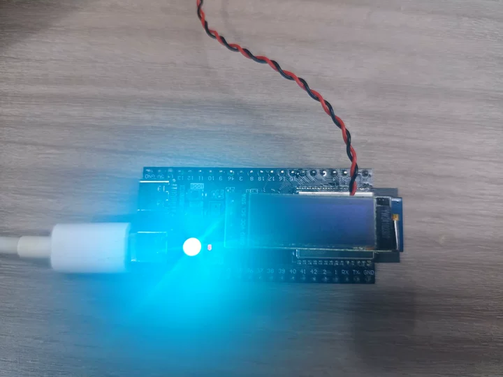
xxxxxxxxxxmain: short press -> playplay: /record.wav — 16000Hz 1ch 72960bytesplay: done — 72960bytes 2156ms
The LED shows a flowing rainbow effect and the speaker outputs sound.
Step 6: Short press the BOOT button while playing
- First short press → pause playback, the DAC mutes immediately, the LED stays at the current color
- Press again → resume playback, the DAC unmutes, the LED flows rainbow again
6.4 Edge Cases
| Scenario | Expected Behavior |
|---|---|
| Short press with no recording file | Prints "play: no file", no exception |
| Long press while playing | Prints "cannot record during playback", no response |
| Long press again while recording | Prints "already recording", no response |
| Recording reaches the 20-second limit | Automatically stops recording and saves the file |
| No operation after power-on | Idle waiting, amplifier on but DAC muted (no noise) |
| Abnormal crash during playback | finally block restores mute, closes file, resets flags |
| Insufficient Flash space | File write fails during recording; finally block reports error and cleans up |
7. FAQ
| Symptom | Cause | Solution |
|---|---|---|
| I2C scan does not show 0x18 | ES8311 not powered / I2C wiring error | Check the SCL(42)/SDA(41) wire order, confirm ES8311 power is normal |
| Recording file is 0 bytes | I2S RX cannot read data (ADC not powered) | Use es8311.dump() to check whether REG0D is 0x02 |
| Pops during playback | I2S format does not match ES8311 configuration | Check REG09/REG0A, bits[1:0]=00 (I2S), bits[3:2]=11 (16-bit) |
| Abnormal playback speed (fast/slow) | Sample rate mismatch | Ensure RATE is consistent in es8311.py and main.py |
| Low recording volume | Insufficient microphone gain | Change MIC at the top of es8311.py to 36 or 42 (dB) |
| Button response is not sensitive | Debounce too short / polling too slow | Adjust DB (30ms) or reduce sleep_ms(20) in the main loop |
| LED does not change during playback | NeoPixel initialization failed / GPIO48 conflict | Check the led.init() output and GPIO48 usage |
MemoryError | Allocating large memory at once | This project is fully stream-processed and should not occur (check whether old code is used) |
| Register dump is all 0 or FF | Unstable I2C communication | REG44 noise immunity has been written twice; try lowering the I2C frequency |
8. Parameter Tuning Guide
8.1 Changing the Volume
xxxxxxxxxx# main.py topVOL = 100 # Playback volume 0-100 (default 90)8.2 Changing the Microphone Gain
xxxxxxxxxx# es8311.py topMIC = 42 # Mic gain dB, options 0/6/12/18/24/30/36/428.3 Changing the Sample Rate
Both locations must be modified at the same time; the MCLK frequency follows automatically (PWM = RATE × 256):
xxxxxxxxxx# es8311.py — Sample rateRATE = 48000# main.py — Sample rateRATE = 480008.4 Changing the Maximum Recording Duration
# main.py topREC_SEC = 60 # seconds, streaming: no memory limit