Welcome to ESP32 Core Board repository
3.Repeater Experiment
Audio Recorder/Player Experiment
Audio Recorder/Player Experiment1. Audio Recording and Playback OverviewWhy Do You Need This Tutorial?Application ScenariosWhat This Project Does1.1 Comparison with the Previous Two Projects2. Core Concepts2.1 Full-Duplex I2S2.2 ES8311 BOTH Mode2.3 Pop Suppression Mechanism2.4 SPIFFS File Storage3. Project Architecture and Flow3.1 Recording Data Flow3.2 Playback Data Flow4. Hardware Dependencies5. Source Code Details5.1 app_speech.h — Macro Configuration and Interfaces5.2 app_speech.c — Full-Duplex Audio Chain5.3 wav_file_player.c — Player (with DAC Gain Control)5.4 main.c — Main Entry and Button State Machine5.5 wav_handler.c — WAV File Read/Write5.6 rgb_led.c — WS2812 RGB LED6. Operation Flow6.1 menuconfig Configuration6.2 Build and Flash6.3 Normal Operation6.4 Edge Cases7. Common Issues
1. Audio Recording and Playback Overview
Why Do You Need This Tutorial?
In embedded audio development, simultaneously implementing recording and playback is a key milestone for advancement. Standalone playback (Audio_Playing) or recording (Audio_Recording) only requires I2S half-duplex mode, whereas recorder/player combo demands full-duplex I2S bus driving both ADC and DAC simultaneously, with careful management of timing and resource sharing between the two. This tutorial is designed to solve this challenge. It not only teaches you how to establish a full-duplex audio chain, but also provides production-ready solutions for pop suppression, button interaction, file storage, and more.
Application Scenarios
The techniques demonstrated in this project can be widely applied to the following scenarios:
Smart Voice Assistants: Complete chain of audio sampling → speech recognition → speech synthesis playback
Intercom/Access Control Systems: Half-duplex communication where pressing the button records (talk) and releasing plays the other party's voice
Audio Memo/Answering Machine: Human interaction paradigm with long press to record, short press to playback
Educational Toys/Learning Devices: Learning feedback loop of echo recording → playback comparison
IoT Voice Alarm: Event-triggered pre-recorded voice, local instant playback
What This Project Does
This project implements a button-driven audio recorder/player that simultaneously drives the ES8311 ADC and DAC via full-duplex I2S bus, supporting dual-mode operation with long-press-to-record and short-press-to-play. Recording data is stored in WAV format in the SPIFFS flash filesystem, with built-in pop suppression mechanism to ensure playback quality.
Core capabilities:
| Function | Description |
|---|---|
| Recording | ES8311 ADC, 16kHz / 16-bit / mono, max 20 seconds, heap memory buffer 640KB |
| Playback | ES8311 DAC, 16kHz / 16-bit / stereo (mono duplicated), SPIFFS storage |
| Button Logic | BOOT button (GPIO0): Long press+hold=record, release=stop; Short press=play/pause/resume |
| LED Feedback | WS2812 RGB LED: Recording=green, Recording done=red, Playing=rainbow color animation |
| Pop Suppression | DAC mute → min gain → mute flush → PA on → DAC stays muted, restore gain and unmute before playback |
1.1 Comparison with the Previous Two Projects
| Feature | Audio_Playing | Audio_Recording | Audio_Play_Record_v2 |
|---|---|---|---|
| DAC Playback | ✓ | ✗ | ✓ |
| ADC Recording | ✗ | ✓ | ✓ |
| I2S Mode | TX only | RX only | TX+RX Full-Duplex |
| Storage | SPIFFS | FAT + USB MSC | SPIFFS |
| LED Driver | Manual RMT | led_strip library | Manual RMT |
| Pop Suppression | PA last on + mute flush | N/A | DAC hardware mute + multi-stage register control |
| Button Logic | Short press play/pause, long press stop | Short press start/stop recording | Short press play/pause/resume, long press record |
2. Core Concepts
2.1 Full-Duplex I2S
Full-duplex means I2S has both TX and RX channels open simultaneously, sharing MCLK / BCLK / WS clock signals:
MCLK (GPIO15)ESP32 ─────────────────────→ ES8311BCLK (GPIO16)ESP32 ─────────────────────→ ES8311WS (GPIO18)ESP32 ─────────────────────→ ES8311DOUT (GPIO8)ESP32 ─────────────────────→ ES8311 SDIN (DAC) ← Playback pathDIN (GPIO17)ESP32 ←───────────────────── ES8311 SDOUT (ADC) ← Recording pathI2C (GPIO41/42)ESP32 ←────────────────────→ ES8311 Control Interface
In full-duplex mode, TX and RX sampling parameters must match (same sample rate, same bit width), because in the standard Philips protocol they share the WS clock.
2.2 ES8311 BOTH Mode
ES8311 is configured in ADC+DAC dual mode (ESP_CODEC_DEV_WORK_MODE_BOTH):
xxxxxxxxxxes8311_codec_cfg_t ecfg = { .codec_mode = ESP_CODEC_DEV_WORK_MODE_BOTH,};esp_codec_dev_cfg_t dc = { .dev_type = ESP_CODEC_DEV_TYPE_IN_OUT, // Input + Output};| Parameter | Value |
|---|---|
| Working Mode | BOTH (ADC + DAC) |
| I2S Clock Source | XTAL (external crystal) |
| Sample Rate | 16000 Hz |
| Bit Depth | 16-bit |
| Channels | Stereo (mono data duplicated to L+R) |
| MIC Gain | 40 dB |
2.3 Pop Suppression Mechanism
Improper startup timing between ES8311 DAC and NS4150 amplifier at power-on can produce a "pop" sound. This project uses a multi-stage suppression strategy based on DAC hardware registers, fundamentally different from the Audio_Playing project's "PA last on + mute flush" strategy:
| Comparison Dimension | Audio_Playing (Player) | Audio_Play_Record_v2 (Recorder/Player) |
|---|---|---|
| Suppression Method | Mute flush + timing control | DAC hardware mute + gain register control + mute flush |
| PA Enable Timing | PA turns on as the final step after I2S+Codec are ready | PA turns on inside init_codec_official(), waiting 100ms for stabilization after |
| DAC State | Set to 90% volume after init, no mute | DAC stays muted (mute=true) after init, only unmutes when playing |
| Before Playback | Only write ~25ms silence preamble | First gain_max() → unmute → wait 10ms → then write silence preamble |
| When Paused | Do not touch DAC | Immediately mute DAC, no noise |
| At End of Playback | Do not touch DAC (only stop task) | Silence trailer → re-mute DAC |
This project's six-stage suppression flow:
xxxxxxxxxxStage 1: DAC mute (mute=true)Stage 2: Enable analog path (REG0E=0x02)Stage 3: Set minimum gain (REG32=0x00)Stage 4: Write silence data to I2S TX pipe (~200ms zero-value PCM), flush residual noiseStage 5: Enable amplifier power (PA=on), wait 100ms for stabilizationStage 6: Keep DAC muted, wait for playback command
Recovery flow when playback starts:
xBefore playback:① app_speech_dac_gain_max() → Set max gain (REG32=0xFF)② app_speech_dac_mute(false) → Unmute③ vTaskDelay(10) → Wait for gain and unmute to take effect④ Write silence buffer as preamble → Flush once more to ensure cleanliness (256×4 bytes)After playback ends:① Write silence buffer as trailer (256×4 bytes)② app_speech_dac_mute(true) → Re-mute
Core Difference: The player relies on "PA last on, I2S already outputting silence" to avoid pops, suitable for pure playback scenarios. The recorder/player introduces DAC hardware mute and gain register control, enabling finer management of mute switching between play/pause/stop, adapting to the complex workflow of combined recording and playback.
2.4 SPIFFS File Storage
This project uses SPIFFS as the storage medium for WAV files (same as Audio_Playing, different from Audio_Recording's FAT + USB MSC).
| Comparison | SPIFFS | FAT + USB MSC |
|---|---|---|
| Direct PC Read | Not supported | Supported (USB drive mode) |
| Wear Leveling | Built-in | Depends on WL layer |
| File Operations | POSIX fopen/fread | POSIX fopen/fread |
| Use Case | Firmware internal read-only resources | Data requiring PC interaction |
3. Project Architecture and Flow
xxxxxxxxxxapp_main()├─ remove(REC_FILE) ← Delete old recording file├─ Codec_I2S_init() ← Full-duplex audio chain initialization│ ├─ power_on_codec() PA pin initialized as output (off)│ ├─ i2c_init() I2C bus + scan│ ├─ i2s_driver_init() I2S TX + RX full-duplex channels│ └─ init_codec_official() ES8311 BOTH mode + pop suppression + PA on + wait stable│├─ wav_player_init() ← SPIFFS mount├─ rgb_led_init() ← WS2812 init and turn off lights├─ malloc(REC_BUF_LEN) ← Pre-allocate 640KB recording buffer│└─ xTaskCreate(v_button_task) ← Button polling taskv_button_task (FreeRTOS Task, 50Hz):while(1):Detect BOOT button (active low)Debounce 30ms|├─ Long press (≥800ms) → Recording flow:│ 1. Set g_recording = true│ 2. xTaskCreate(v_record_task) Start recording task│ 3. Wait for release (while button not released)│ 4. Set g_recording = false│ 5. Wait for recording task to exit│└─ Short press (<800ms) → Playback flow:1. Playing and paused → wav_player_resume()2. Playing and not paused → wav_player_pause()3. Idle → wav_player_play_file(REC_FILE)v_record_task (FreeRTOS Task):while(g_recording):i2s_channel_read(rx_handle_) → Extract left channel from stereo pair → g_rec_bufg_rec_len > 0 → wav_save_file("/spiffs/record.wav")v_wav_play_task (wav_file_player.c, FreeRTOS Task):fopen → read WAV header → app_speech_dac_gain_max() → unmute → loop:fread(mono) → mono→stereo copy → i2s_channel_write(tx)When paused: while(s_is_paused) vTaskDelay→ Silence flush → mute → fclose
3.1 Recording Data Flow
xxxxxxxxxxES8311 ADC → I2S DIN(GPIO17) → i2s_channel_read(rx_handle_)→ Stereo pair {L0,R0,L1,R1,...} → Extract left channel {L0,L1,...}→ g_rec_buf[heap]→ wav_save_file() → SPIFFS /spiffs/record.wav
3.2 Playback Data Flow
xxxxxxxxxxSPIFFS /spiffs/record.wav → fopen/fread → mono PCM→ Mono→Stereo copy → i2s_channel_write(tx_handle_)→ I2S DOUT(GPIO8) → ES8311 DAC → NS4150 PA → Speaker
4. Hardware Dependencies
Hardware Connections:
| Pin | Function | Connected To |
|---|---|---|
| GPIO42 | I2C SCL | ES8311 SCL |
| GPIO41 | I2C SDA | ES8311 SDA |
| GPIO15 | I2S MCLK | ES8311 MCLK |
| GPIO16 | I2S BCLK | ES8311 BCLK |
| GPIO18 | I2S WS | ES8311 LRCK |
| GPIO8 | I2S DOUT | ES8311 SDIN (DAC) |
| GPIO17 | I2S DIN | ES8311 SDOUT (ADC) |
| GPIO7 | PA_EN | NS4150 amplifier enable |
| GPIO48 | WS2812 Data | RGB LED |
| GPIO0 | BOOT button | Active low |
Required Components: driver/i2s_std / driver/i2c_master / driver/rmt_tx / esp_spiffs / FreeRTOS
This project uses third-party libraries again: For details, refer back to (Detailed third-party library installation process: 2.Basic Peripherals→10.RGB LED Effects)
Note:
esp_codec_devand its dependencyes8311are third-party components provided by the ESP-IDF Component Registry, not built into IDF. Before using, declare the dependency inmain/idf_component.yml, otherwise compilation will fail to find the header file:xxxxxxxxxx## IDF Component Manager Manifest Filedependenciesidfversion'>=4.1.0'espressif/esp_codec_dev^1.5.10After declaration, executing
idf.py buildwill cause the Component Manager to automatically download the component to themanaged_components/directory.es8311is a transitive dependency ofesp_codec_devand does not need to be declared separately.
5. Source Code Details
Complete source code: Source Code → ESP-IDF → 6.Audio → Audio_Play_Record_v2
5.1 app_speech.h — Macro Configuration and Interfaces
The header file centrally manages full-duplex I2S pin definitions, audio parameters, and channel handles, serving as the "configuration hub" for the entire audio chain. The following macro definitions and global declarations determine the hardware pins and audio quality parameters for recording/playback:
xxxxxxxxxx/* I2S Full-Duplex Pins */// Master Clock// Bit Clock// Word Select (LRCK)// RX: ES8311 ADC → ESP32// TX: ESP32 → ES8311 DAC
/* Audio Parameters */// Mic Gain 40dB// Max Output Volume// Sample Rate 16kHz// MCLK Multiple
/* Global I2S Channel Handles */extern i2s_chan_handle_t tx_handle_; // I2S TX Channelextern i2s_chan_handle_t rx_handle_; // I2S RX ChannelInterface list:
| Function | Description |
|---|---|
Codec_I2S_init() | Initialize full-duplex audio chain |
app_speech_record(buf, len, &read) | Read PCM from I2S RX |
app_speech_play(buf, len, &written) | Write PCM to I2S TX |
app_speech_pa_control(on) | Control amplifier on/off |
app_speech_dac_mute(mute) | Control DAC mute |
app_speech_dac_gain_set(gain) | Set DAC volume (0-90) |
app_speech_dac_gain_max() | Set DAC max gain (REG32=0xFF) |
5.2 app_speech.c — Full-Duplex Audio Chain
i2s_driver_init() — Full-duplex channel creation
This function is the core of what distinguishes this project from the previous two half-duplex projects: a single i2s_new_channel() call obtains both TX and RX channel handles simultaneously, both sharing the same clock parameters (std_cfg), ensuring strict consistency of sample rate and bit width in full-duplex mode.
xxxxxxxxxx/* Channel Config: Master Mode */i2s_chan_config_t cc = {    .id   = I2S_NUM,    .role = I2S_ROLE_MASTER,          // ESP32 provides clocks};// Create TX & RX bothi2s_new_channel(&cc, &tx_handle_, &rx_handle_);
/* Initialize TX Channel */i2s_channel_init_std_mode(tx_handle_, &std_cfg);i2s_channel_enable(tx_handle_);
/* Initialize RX Channel (shares same std_cfg parameters as TX) */if (rx_handle_ != NULL) {    i2s_channel_init_std_mode(rx_handle_, &std_cfg);    i2s_channel_enable(rx_handle_);}
TX and RX use the same
std_cfg(sample rate, bit width, channel mode all match), because they share the WS clock.
init_codec_official() — BOTH mode + Pop Suppression
This function is the final step in audio chain initialization: configure ES8311 in ADC+DAC dual working mode, then execute the six-stage pop suppression sequence in strict order, ensuring the amplifier produces no "pop" sound at power-on.
xxxxxxxxxx/* ES8311 Codec → BOTH mode (ADC + DAC) */es8311_codec_cfg_t ecfg = {    .codec_mode = ESP_CODEC_DEV_WORK_MODE_BOTH,};
/* Device Type: Input + Output */esp_codec_dev_cfg_t dc = {    .dev_type = ESP_CODEC_DEV_TYPE_IN_OUT,};
/* ====== Pop Suppression Sequence ====== */
// 1. DAC muteesp_codec_dev_set_out_mute(codec_dev_, true);
// 2. Enable analog pathesp_codec_dev_write_reg(codec_dev_, 0x0E, 0x02);
// 3. Set minimum gainesp_codec_dev_write_reg(codec_dev_, 0x32, 0x00);
// 4. Flush I2S pipe with silence data (~200ms zero-value PCM)int16_t *z = calloc(1, EXAMPLE_SAMPLE_RATE * 4 / 5);i2s_channel_write(tx_handle_, z, EXAMPLE_SAMPLE_RATE * 4 / 5,                  &w, pdMS_TO_TICKS(300));free(z);
// 5. Power on amplifierapp_speech_pa_control(true);vTaskDelay(pdMS_TO_TICKS(100));       // Wait for PA stable
// 6. Keep DAC muted, wait for playback command
Core idea of pop suppression: Flush the entire I2S pipe clean before the amplifier powers on, ensuring no noise gets amplified when the amplifier turns on.
5.3 wav_file_player.c — Player (with DAC Gain Control)
Compared with the Audio_Playing project, v2's player integrates DAC gain and mute control:
wav_player_init() — SPIFFS mount, auto-format on first use. Suppress W-level warnings triggered by format_if_mount_failed by temporarily elevating the log level:
xxxxxxxxxxvoid wav_player_init(void){ esp_vfs_spiffs_conf_t conf = { .base_path = "/spiffs", .partition_label = "storage", .max_files = 5, // Auto-format on first boot .format_if_mount_failed = true, }; // Suppress auto-format W-level log esp_log_level_set("SPIFFS", ESP_LOG_ERROR); esp_vfs_spiffs_register(&conf); esp_log_level_set("SPIFFS", ESP_LOG_WARN); s_is_playing = false; ESP_LOGI(TAG, "SPIFFS mounted");}"Voice onset" flow before playback starts — First restore gain, then unmute, with a silence data buffer as preamble to completely eliminate playback start pops:
xxxxxxxxxx/* Pop-Free Start: Max Gain → Unmute → Silence Cushion → Audio  */app_speech_dac_gain_max();      // REG32 = 0xFF Max Gainapp_speech_dac_mute(false);     // UnmutevTaskDelay(10);                 // Wait for registers to take effect
/* Pre-audio silence cushion to ensure DAC output is stable */memset(stereo_buf, 0, 256 * 4);i2s_channel_write(tx_handle_, stereo_buf, 256 * 4, &wd, pdMS_TO_TICKS(50));
"Voice offset" flow after playback ends — First flush silence data to clear residual I2S pipe content, then re-mute DAC, ensuring zero output from speaker during non-playback periods:
xxxxxxxxxx/* Pop-Free End: Silence Flush → Re-Mute */memset(stereo_buf, 0, 256 * 4);i2s_channel_write(tx_handle_, stereo_buf, 256 * 4, &wd, pdMS_TO_TICKS(50));app_speech_dac_mute(true);Comparison with Audio_Playing: v1 only writes silence frames, v2 adds DAC mute/gain codec-level control on top.
Pause/Resume with DAC linkage — Mute immediately when pausing to avoid noise, unmute first when resuming before setting the flag, ensuring DAC is ready before audio data arrives:
xxxxxxxxxxvoid wav_player_pause(void) {    s_is_paused = true;                  // Mark as paused    app_speech_dac_mute(true);           // Mute immediately}
void wav_player_resume(void) {    app_speech_dac_mute(false);          // Unmute first    s_is_paused = false;                 // Then clear flag}
5.4 main.c — Main Entry and Button State Machine
Button logic — A button state machine based on duration discrimination: first debounce 30ms, then poll to measure hold duration. ≥800ms is long press (record), <800ms is short press (play/pause/resume):
xxxxxxxxxx// Debounce Time (ms)// Long-Press Threshold (ms)
/* Detect press: Debounce then measure duration */if (gpio_get_level(BUTTON_PIN) == 0) { vTaskDelay(DEBOUNCE_MS / portTICK_PERIOD_MS); // Skip if debounce failed if (gpio_get_level(BUTTON_PIN) != 0) continue;
int hold_ms = 0; /* Measure hold duration */ while (gpio_get_level(BUTTON_PIN) == 0) { vTaskDelay(50); hold_ms += 50; if (hold_ms >= LONG_PRESS_MS) break; }
if (hold_ms >= LONG_PRESS_MS) { /* === Long Press: Start Recording === */ if (wav_player_is_busy()) { // Cannot record during playback ESP_LOGW(TAG, "Cannot record during playback"); } else if (g_recording) { // Already recording ESP_LOGW(TAG, "Already recording"); } else { g_recording = true; xTaskCreate(v_record_task, "record", 8192, NULL, 5, NULL);
/* Wait for release to stop recording */ while (gpio_get_level(BUTTON_PIN) == 0) vTaskDelay(50); g_recording = false; vTaskDelay(pdMS_TO_TICKS(300));
/* Ensure record task has exited */ while (g_recording) vTaskDelay(pdMS_TO_TICKS(10)); } } else { /* === Short Press: Play/Pause/Resume === */ if (wav_player_is_busy()) { if (wav_player_is_paused()) wav_player_resume(); else wav_player_pause(); } else { wav_player_play_file(REC_FILE); } /* Wait for release */ while (gpio_get_level(BUTTON_PIN) == 0) vTaskDelay(pdMS_TO_TICKS(10)); }}Recording task — Extract left channel from stereo — ES8311 I2S RX returns interleaved stereo data (L0,R0,L1,R1,...), but the actual MIC signal only exists in the left channel slot. Right channel data needs to be discarded to extract pure mono PCM. LED is green during recording, briefly red then off after completion:
xxxxxxxxxx/* FRAME_SIZE = 1920 bytes, DMA-aligned frame size */int16_t *rx_buf = malloc(FRAME_SIZE);g_rec_len = 0;// Recording: Green LEDrgb_led_set(0, 255, 0);
while (g_recording) {    /* Buffer overflow guard */    uint32_t remaining = REC_BUF_LEN - g_rec_len;    if (remaining < FRAME_SIZE / 2) break;
    i2s_channel_read(rx_handle_, (uint8_t *)rx_buf,                     FRAME_SIZE, &bytes_read, pdMS_TO_TICKS(200));
    /* Stereo Interleaved → Mono Extract     * {L0,R0, L1,R1, L2,R2, ...} → {L0, L1, L2, ...}  */    // 4 bytes per (L+R) pair    int npairs = bytes_read / 4;    for (int i = 0; i < npairs; i++) {        // Left channel only        g_rec_buf[g_rec_len / 2 + i] = rx_buf[i * 2];    }    g_rec_len += npairs * 2;}
// Done: Red LED → Save → Offrgb_led_off();rgb_led_set(255, 0, 0);free(rx_buf);
if (g_rec_len > 0) {    wav_save_file(REC_FILE, (uint8_t *)g_rec_buf, g_rec_len);    rgb_led_off();}
Why extract left channel? ES8311 is configured for stereo I2S in BOTH mode, but recording only needs mono. MIC signal appears in the left channel slot, right channel is silence or noise, which can be discarded directly.
LED effect logic — Main loop only manages rainbow LED effect during playback. Recording LED effects (green/red) are controlled internally by the recording task itself, achieving separation of concerns:
xxxxxxxxxx/* Recording task controls its own LED (Green=recording, Red=done) *//* Main loop only controls playback LED */if (wav_player_is_playing()) { // Playing: Rainbow animation rgb_led_rainbow_step();} else { // Not playing: Off rgb_led_off();}5.5 wav_handler.c — WAV File Read/Write
Same WAV processing module as Audio_Recording project, providing:
wav_create_header()— Fill WAV header magic number and PCM format parameterswav_save_file()— PCM buffer → WAV file (auto-generate 44-byte header)wav_load_file()— WAV file → PCM buffer (parse and skip header, verify RIFF magic)
5.6 rgb_led.c — WS2812 RGB LED
Same RMT driver implementation as Audio_Playing project:
80MHz RMT clock → 12.5ns/tick resolution
GRB byte order encoding
Rainbow hue HSV sector algorithm (6 sectors, 1.4° per step)
6. Operation Flow
6.1 menuconfig Configuration
This project depends on a custom partition table (including SPIFFS storage partition) and PSRAM. The following configuration options must be enabled in menuconfig before compilation. For detailed instructions on general settings such as the partition table and Flash size (including menuconfig screenshots), please refer to Section 4.2.1 in 3.Serial Communication and Storage System->6. USB Emulated Mass Storage Experiment.
| Config Path | Setting | Value | Description |
|---|---|---|---|
Serial flasher config → Flash size | Flash size | 16 MB | Match onboard 16MB SPI Flash |
Partition Table → Partition Table | Custom partition table CSV | partitions.csv | Custom partition (with 4M SPIFFS storage) |
Component config → ESP PSRAM | Support for external PSRAM | Enable | Enable 8MB PSRAM |
Component config → ESP PSRAM | Allow malloc() in external memory | Enable | Allow malloc to allocate from PSRAM (640KB recording buffer) |
Component config → ESP PSRAM | Allow .bss segment in external memory | Enable | Allow task stack to use PSRAM |
Component config → SPIFFS Configuration | Maximum Number of Partitions | 3 | SPIFFS max partition count |
Component config → SPIFFS Configuration | Use magic | Enable | Enable magic number check, prevent filesystem corruption |
Component config → SPIFFS Configuration | Use magic length | Enable | Enable length magic check |
Component config → SPIFFS Configuration | Use modification time | Enable | Enable file modification timestamp |
The above configuration is written to the project's
sdkconfig.defaults. After executingidf.py set-target esp32s3, IDF will automatically apply it. If compilation errors indicate a feature is not enabled, enteridf.py menuconfigto check each item.
xxxxxxxxxx# Flash sizeCONFIG_ESPTOOLPY_FLASHSIZE_16MB=y# Custom partition tableCONFIG_PARTITION_TABLE_CUSTOM=yCONFIG_PARTITION_TABLE_CUSTOM_FILENAME="partitions.csv"# PSRAM / External RAMCONFIG_SPIRAM=yCONFIG_SPIRAM_USE_MALLOC=yCONFIG_SPIRAM_ALLOW_STACK_EXTERNAL_MEMORY=yCONFIG_SPIRAM_MODE_OCT=yCONFIG_SPIRAM_SPEED_80M=y# SPIFFSCONFIG_SPIFFS_MAX_PARTITIONS=3CONFIG_SPIFFS_USE_MAGIC=yCONFIG_SPIFFS_USE_MAGIC_LENGTH=yCONFIG_SPIFFS_USE_MTIME=y
6.2 Build and Flash
ESP-IDF flashing process: See ESP-IDF → 1. Before Development → 3. Build and Flash.
6.3 Normal Operation
Step 1: Confirm hardware connections
This development board has ES8311 audio codec chip, NS4150 amplifier, and WS2812 RGB LED onboard. No external modules needed, ready to use after power-on. Ensure speaker is properly connected to amplifier output.
Step 2: Power on and reset, observe serial output:
xxxxxxxxxxI (1083) MAIN: Audio Player/Recorder v2I (1193) app_speech: I2C ok SDA:41 SCL:42I (1363) app_speech: I2S ready MCLK:15 BCLK:16 WS:18 DOUT:8 DIN:17I (1603) app_speech: ES8311 ok REG32=0x00 REG0E=0x00 PA=on MUTEDI (17633) WAV_PLAYER: SPIFFS mountedI (17633) MAIN: Long press+hold: record | Short press: play/pause/resume
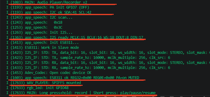
Startup log outputs in sequence: I2C bus ready → I2S full-duplex channel established → ES8311 initialization and pop suppression complete (PA on but DAC muted) → SPIFFS mounted → Button hint. Old recording file is automatically deleted after power-on.
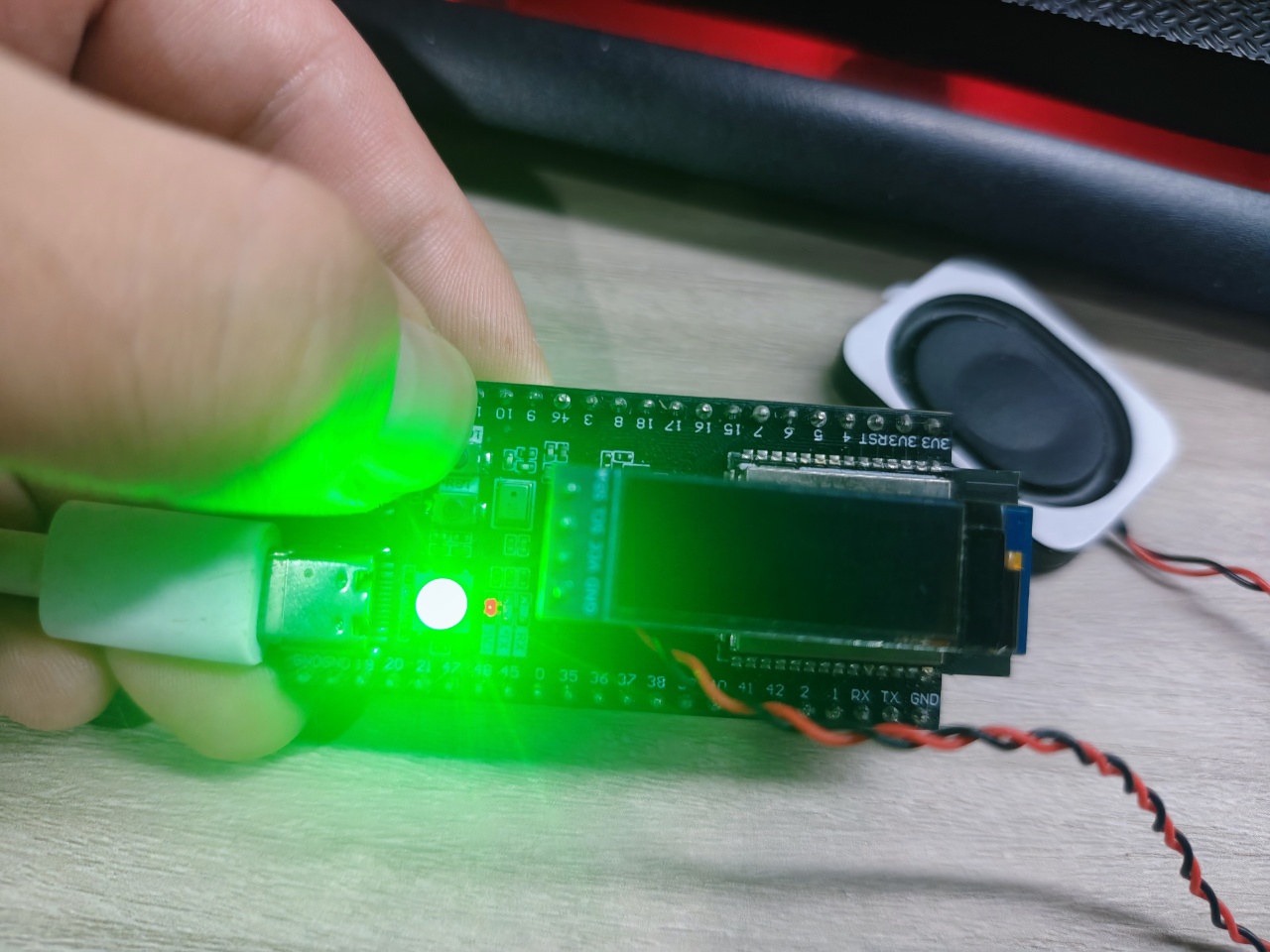
Step 3: Long press and hold BOOT button (>0.8s) to start recording:
xxxxxxxxxxI (213453) MAIN: Long press -> start recording (hold to keep)I (213453) MAIN: Recording started
LED turns green, indicating recording in progress. Speak toward the onboard MIC.
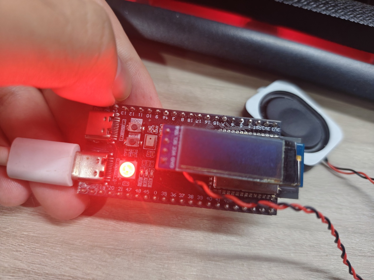
Step 4: Release BOOT button to stop recording:
xxxxxxxxxxI (219053) MAIN: Button released -> stop recordingI (220883) wav: Save OK: /spiffs/record.wavI (220883) MAIN: Rec: 186240 bytes 5600ms -> 33257 B/s (expect 32000)
LED turns red (briefly), then goes off. Recording data is saved to SPIFFS flash in WAV format.

Step 5: Short press BOOT button (<0.8s) to play the just-recorded audio:
xxxxxxxxxxI (8200) main: Short press -> playI (8200) WAV_PLAYER: Start: /spiffs/record.wav (1ch 16bit 16000Hz 48000bytes)I (11200) WAV_PLAYER: Play: sent=48000 dur=3000ms -> 16000 B/s (expect 32000)
LED shows rainbow flowing effect, speaker outputs the just-recorded sound. DAC gain automatically restores to maximum during playback, and re-mutes after playback ends.
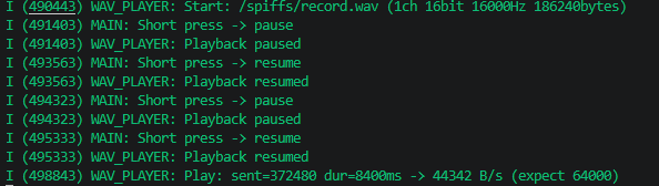
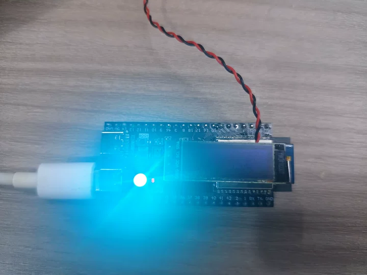
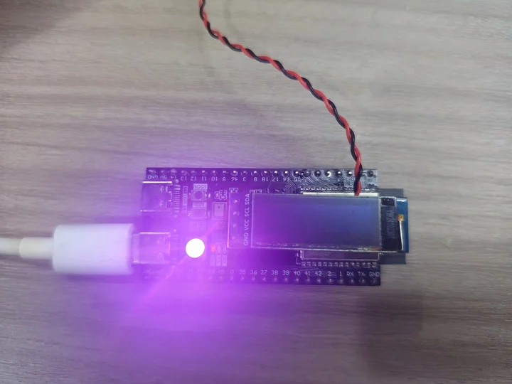
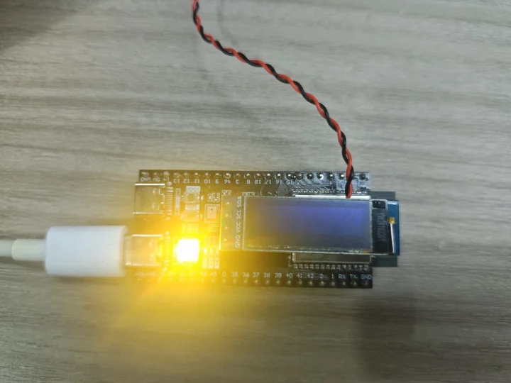
Step 6: Short press BOOT button during playback:
First short press → Pause playback, DAC immediately mutes, LED goes off
Short press again → Resume playback, DAC unmutes, LED rainbow resumes flowing
Playback reaches end of file → Auto stop, DAC re-mutes, LED goes off
6.4 Edge Cases
| Scenario | Expected Behavior |
|---|---|
| Short press with no recording file | Playback fails, error log printed |
| Long press during playback | Warning printed "Cannot record during playback" |
| Long press while already recording | Warning printed "Already recording" |
| Recording buffer full at 20 seconds | Auto stop recording |
| No operation after power-on | Idle wait, amplifier on but DAC muted (no noise) |
7. Common Issues
| Symptom | Cause | Solution |
|---|---|---|
| No sound in playback/recording | I2S clock config error | Check MCLK/BCLK/WS pin connections |
| Pop sound during playback | Pop suppression sequence not executed | Verify mute→gain→amplifier flow in init_codec_official() |
| Recording file empty or all zeros | I2S DIN (GPIO17) not connected / ES8311 ADC not enabled | Check hardware connections and ADC initialization |
| Recording volume too low | MIC gain insufficient | Increase EXAMPLE_MIC_GAIN (max 42dB) |
| Abnormal playback speed | WAV file sample rate doesn't match playback params | Ensure both recording and playback use 16kHz |
| Noise during recording | MIC bias power unstable | Check if amplifier GPIO7 is enabled (provides MIC bias) |
| Button unresponsive | Debounce time insufficient / polling frequency too low | Increase DEBOUNCE_MS or reduce polling interval |
| LED doesn't change during playback | RMT init failed / pin conflict | Check if GPIO48 is used by other functions |
| Heap memory allocation failed | Insufficient 640KB contiguous memory | Check memory usage, consider reducing REC_MAX_SEC |
| Recording buffer full | Reached 20-second recording limit | Increase REC_MAX_SEC (note memory constraints) |