Welcome to ESP32 Core Board repository
6. ADC
ADC
ADC1. ADC Overview2. Core Concepts2.1 How the SAR ADC Works2.2 ADC Attenuation2.3 ADC Reading and Voltage Conversion2.4 Averaging Filter2.5 Core API3. Hardware Dependencies4. Project Architecture and Flow5. Source Code Details5.1 Parameter Configuration and Initialization5.2 Averaged Sampling and Voltage Conversion6. Operation Procedure6.1 Flashing and Running6.2 Normal Phenomenon6.3 Verification Methods7. Common Problems
1. ADC Overview
ADC (Analog-to-Digital Converter) converts an analog voltage into a digital value. This experiment uses the SAR ADC of the ESP32-S3 to read the voltage on the GPIO4 pin, taking 16 consecutive samples per batch and averaging them, then printing the raw ADC value and the converted voltage (mV) via serial. Averaging filtering effectively suppresses the random noise of a single sample.
Typical application scenarios:
| Application Type | Example |
|---|---|
| Sensor reading | Potentiometers, photoresistors, thermistors, current sensors |
| Battery level detection | Lithium battery voltage monitoring |
| Audio capture | Microphone analog signal (with DMA) |
| Touch detection | Capacitive touch (dedicated touch sensors) |
2. Core Concepts
2.1 How the SAR ADC Works
The ESP32-S3 uses a SAR ADC (Successive Approximation Register type). The core idea is binary-search approximation: comparing the input voltage with the DAC output voltage bit by bit from the MSB to the LSB, with 12-bit resolution requiring 12 clock cycles to complete one conversion.
2.2 ADC Attenuation
By default, the ADC of the ESP32-S3 can only measure 0~1.1V. The range can be extended by setting the attenuator:
| Attenuation | ADC Constant | Range | Use Case |
|---|---|---|---|
| 0 dB | ADC.ATTN_0DB | 0 ~ 1.1V | Small signals |
| 2.5 dB | ADC.ATTN_2_5DB | 0 ~ 1.5V | — |
| 6 dB | ADC.ATTN_6DB | 0 ~ 2.2V | — |
| 11 dB | ADC.ATTN_11DB | 0 ~ 3.3V | General (most commonly used) |
Choose
ATTN_11DBto cover the full 0~3.3V range, which suits most cases.
2.3 ADC Reading and Voltage Conversion
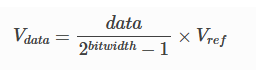
adc.read() returns a 12-bit raw value (0~4095). The conversion formula is:
Voltage formula without attenuation:
Vdata = (data / (2^bitwidth - 1)) × Vref
Voltage formula with attenuation:
xxxxxxxxxxVdata = (data / (2^bitwidth - 1)) × Vref / k
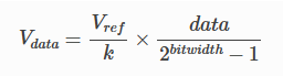
The effective precision of the ESP32-S3 ADC is about 11-12 bits; noise in the low bits is normal. This experiment averages 16 samples to reduce noise.
2.4 Averaging Filter
xxxxxxxxxxsum_val = 0for i in range(SAMPLE_COUNT): sum_val += adc.read() # 16 consecutive samplesavg_raw = sum_val // SAMPLE_COUNT # averageAveraging filtering is the simplest digital filter. Averaging 16 samples reduces the standard deviation of random noise to 1/4 of its original value.
2.5 Core API
xfrom machine import ADC, Pin
adc = ADC(Pin(4)) # create the ADC objectadc.atten(ADC.ATTN_11DB) # set attenuation, range 0~3.3Vval = adc.read() # read a 12-bit value (0~4095)3. Hardware Dependencies
| GPIO | Peripheral | Mode | Description |
|---|---|---|---|
| 4 | ADC1_CH3 | ADC | Analog input pin, connect the voltage to be measured |
In this experiment, you can leave GPIO4 floating to observe the fluctuating reading, or connect an external potentiometer to verify the voltage change.
4. Project Architecture and Flow
xxxxxxxxxxScript execution (single-file .py)│├─ Parameter config: ADC_PIN=4, SAMPLE_COUNT=16, VREF=3300mV├─ adc = ADC(Pin(4)) // GPIO4 → ADC├─ adc.atten(ADC.ATTN_11DB) // range 0~3.3V│└─ while True: // sampling loop (once per second)├─ sum_val = 0 // clear the accumulator├─ for i in 0..15: // take 16 consecutive samples│ └─ sum_val += adc.read() // accumulate the 12-bit values├─ avg_raw = sum_val // 16 // take the average├─ avg_mv = avg_raw * 3300 // 4095 // convert to mV├─ print("ADC_Value=..., Voltage=...mV") // serial output└─ sleep_ms(1000) // 1s interval
5. Source Code Details
Full source code: 5.Source Code → MicroPython → 1.Basic Peripherals → 6.ADC → 6.ADC.py
5.1 Parameter Configuration and Initialization
xxxxxxxxxxfrom machine import ADC, Pin  # ADC and Pin classesimport time                    # delay
# Configuration parametersADC_PIN       = 4              # ADC pin (ADC1 CH3)SAMPLE_COUNT  = 16             # samples per batchADC_VREF_MV   = 3300           # reference voltage (mV)ADC_MAX_COUNT = 4095           # 12-bit full scale
# Init ADC (11dB → 0~3.3V, 12-bit)adc = ADC(Pin(ADC_PIN))adc.atten(ADC.ATTN_11DB)
ATTN_11DBextends the range to cover 0~3.3V.adc.read()returns a 12-bit raw value (0~4095).
5.2 Averaged Sampling and Voltage Conversion
xxxxxxxxxxwhile True:    sum_val = 0
    for i in range(SAMPLE_COUNT):        sum_val += adc.read()       # 12-bit raw value
    avg_raw = sum_val // SAMPLE_COUNT    avg_mv  = (avg_raw * ADC_VREF_MV) // ADC_MAX_COUNT
    # ADC raw value + voltage (mV)    print("ADC_Value=%4d, Voltage=%4d mV" % (avg_raw, avg_mv))
    time.sleep_ms(1000)
6. Operation Procedure
6.1 Flashing and Running
Thonny IDE steps: See the 1. Before Development → 3.Thonny IDE chapter.
6.2 Normal Phenomenon
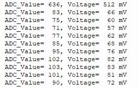
The Thonny Shell prints one line per second:
xxxxxxxxxxADC_Value= 636, Voltage= 512 mVADC_Value= 83, Voltage= 66 mVADC_Value= 75, Voltage= 60 mVADC_Value= 71, Voltage= 57 mVADC_Value= 77, Voltage= 62 mVADC_Value= 85, Voltage= 68 mVADC_Value= 95, Voltage= 76 mVADC_Value= 102, Voltage= 82 mVADC_Value= 103, Voltage= 83 mVADC_Value= 101, Voltage= 81 mV...
When GPIO4 is floating, the reading fluctuates (normal, pin floating)
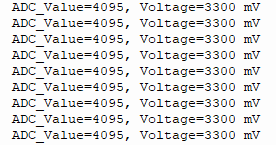
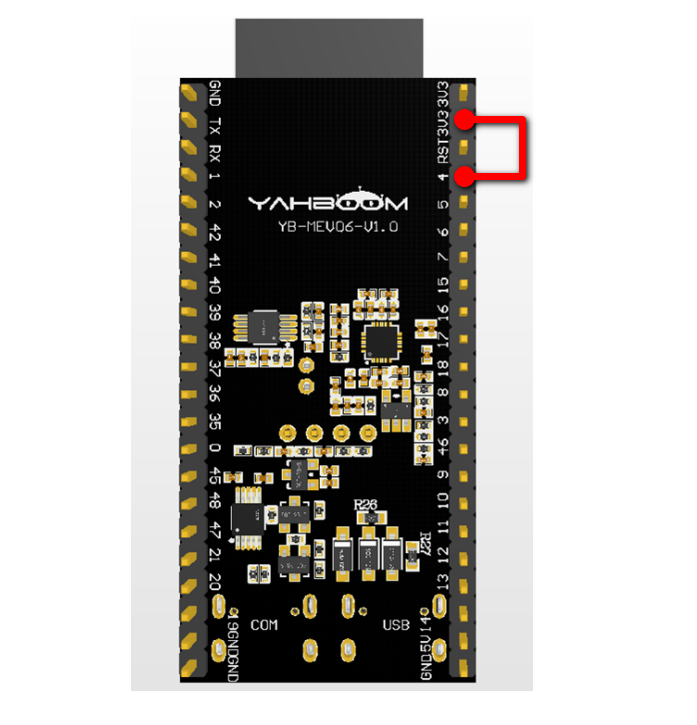
Connect 3.3V → the reading is close to 4095, the voltage about 3300mV
Wiring method:
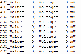
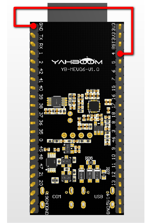
Connect GND → the reading is close to 0
Wiring method:
6.3 Verification Methods
| Operation | Expected Result |
|---|---|
| GPIO4 floating | Reading fluctuates randomly |
| GPIO4 connected to 3.3V | Reading ~4095, voltage ~3300mV |
| GPIO4 connected to GND | Reading ~0, voltage ~0mV |
| Connect the middle pin of a potentiometer | Rotating the potentiometer continuously changes the reading and voltage |
Change SAMPLE_COUNT=16 to SAMPLE_COUNT=1 | Output jitter increases noticeably |
7. Common Problems
| Symptom | Cause | Solution |
|---|---|---|
| Reading always close to 0 | Pin floating + no internal pull-up | Connect an external test voltage or potentiometer to GPIO4 |
| Reading fluctuates wildly | ADC noise is a normal phenomenon | Increase SAMPLE_COUNT or use a hardware filter capacitor |
| Converted voltage always too small | ADC reference or attenuation error | Measure with a multimeter and do a linear calibration |
Pin(4) errors or abnormal readings | GPIO4 conflicts with strapping pins | Use another ADC1 pin |
| Some pin readings wrong after WiFi is enabled | ADC2 channel is used | Switch to an ADC1 channel (GPIO1~9) |