Welcome to ESP32 Core Board repository
4.Binary Semaphore
Binary Semaphore
Binary Semaphore1. Binary Semaphore Overview2. Core Concepts2.1 How Binary Semaphores Work2.2 Semaphore Creation API2.3 Semaphore Operations API2.4 Why Must Use FromISR Version in ISR2.5 Semaphore vs Mutex3. Project Architecture and Flow4. Hardware Dependencies5. Source Code Analysis5.1 Header Files and Macro Configuration5.2 Rainbow Color Definition5.3 button_isr_handler() — GPIO Interrupt Service Routine5.4 vButtonTask() — Button Handling Task5.5 run_marquee_effect() — Marquee5.6 app_main() — Main Entry6. Operation Flow6.1 Compilation and Flashing Flow6.2 Normal Operation7. FAQ
1. Binary Semaphore Overview
Binary Semaphore is the lightest synchronization mechanism in FreeRTOS. It has only two states (0 and 1), and its typical use is ISR → Task notification — when a hardware interrupt occurs, the ISR gives the semaphore, and the task blocked waiting for the semaphore wakes up to process.
Why are Binary Semaphores important? In embedded systems, communication between tasks and interrupts is an unavoidable requirement. Interrupts require extremely fast response and cannot block, while tasks need space for time-consuming processing — these two are inherently contradictory. Binary semaphores are precisely the "bridge" that solves this contradiction: ISR does the minimum (Give semaphore), delegating heavy work to tasks, ensuring both interrupt real-time performance and business logic completeness.
Common application scenarios:
| Scenario | ISR Source | Task Action |
|---|---|---|
| Button/touch detection | GPIO interrupt | Debounce, state machine, UI logic |
| Sensor data ready | SPI/I2C DMA completion interrupt | Parse data, filter, report |
| Wireless packet notification | WiFi/BLE MAC layer interrupt | Protocol stack processing, application layer callback |
| Timer expiration | Hardware Timer interrupt | Periodic sampling, timeout processing |
| ADC conversion complete | ADC interrupt | Read result, calculate, calibrate |
| Encoder pulse | Encoder external interrupt | Position/speed calculation |
One-sentence summary: Whenever a task needs to intervene after an interrupt occurs, binary semaphore is appropriate.
This project demonstrates: button (GPIO0 falling edge interrupt) → ISR gives semaphore → task wakes up → debounce confirmation → accumulated count → light up corresponding color LED. After 7 presses, trigger rainbow marquee, counter resets to zero.
2. Core Concepts
2.1 How Binary Semaphores Work
Initial value = 0│xSemaphoreTake() ──► Block (value is 0, cannot get)│ISR triggers: xSemaphoreGiveFromISR() value becomes 1│xSemaphoreTake() ──► Acquired (value returns to 0)
Binary Semaphore = Queue with only one element, having an element means "signal present" (1), no element means "no signal" (0).
2.2 Semaphore Creation API
x// Binary semaphore — initial value=0SemaphoreHandle_t xSemaphoreCreateBinary(void);
// Counting semaphore — specify initial and maxSemaphoreHandle_t xSemaphoreCreateCounting( UBaseType_t uxMaxCount, // Max count UBaseType_t uxInitialCount // Initial count);2.3 Semaphore Operations API
| API | Context | Function |
|---|---|---|
xSemaphoreTake(handle, timeout) | Task | Wait to acquire semaphore (0→1 taken, returns to 0) |
xSemaphoreGive(handle) | Task | Give semaphore (0→1) |
xSemaphoreGiveFromISR(handle, &pxWoken) | ISR | Give semaphore from ISR |
2.4 Why Must Use FromISR Version in ISR
xxxxxxxxxx// Wrong: normal API in ISRxSemaphoreGive(xSemaphore);  // ❌ Forbidden
// Correct: FromISR in ISRBaseType_t xHigherPriorityTaskWoken = pdFALSE;xSemaphoreGiveFromISR(xSemaphore, &xHigherPriorityTaskWoken);  // ✅ OKif (xHigherPriorityTaskWoken == pdTRUE) {    portYIELD_FROM_ISR();  // Trigger task switch}
Normal APIs call operations that may cause blocking (such as disabling interrupts), which are not available in ISR context. The FromISR version is a lightweight implementation specifically designed for non-blocking ISR calls.
Why initial value = 0? Ensures task starts blocked at
xSemaphoreTakeuntil the first ISR signal arrives. This is the standard ISR→task synchronization pattern.
2.5 Semaphore vs Mutex
| Feature | Binary Semaphore | Mutex |
|---|---|---|
| Purpose | Synchronization (event notification) | Mutual exclusion (resource protection) |
| Any task can Give | ✓ (unblock) | ✗ (only task that took can give) |
| Priority inheritance | None | Yes |
| Can Give in ISR | ✓ (FromISR) | ✗ |
| Initial value | Usually 0 | 1 |
3. Project Architecture and Flow
xxxxxxxxxxapp_main()├─ xSemaphoreCreateBinary() ← Create binary semaphore (initial=0)├─ gpio_config() + ISR ← GPIO0 falling edge interrupt├─ led_strip_init() ← WS2812 (GPIO48, RMT 10MHz)└─ xTaskCreate(vButtonTask) ← Button handling task (Prio 3)GPIO0 falling edge ─► ISR ──(GiveFromISR)──► xButtonSemaphore│(Take, blocking wait)▼vButtonTask│Increment count → Light up corresponding color LED7 times → marquee → counter reset
Button→LED Color Mapping:
| Button Presses | Color | Meaning |
|---|---|---|
| 1st | Red | — |
| 2nd | Orange | — |
| 3rd | Yellow | — |
| 4th | Green | — |
| 5th | Cyan | — |
| 6th | Blue | — |
| 7th | Purple → Marquee | Trigger special effect, counter resets |
4. Hardware Dependencies
| Pin | Function | Description |
|---|---|---|
| GPIO 0 | BOOT button | Falling edge interrupt, internal pull-up |
| GPIO 48 | WS2812 RGB LED | RMT peripheral driver |
Required Components: freertos/FreeRTOS, freertos/task, freertos/semphr, driver/gpio, led_strip, esp_log
This project uses a third-party library again: For details, review (Third-party library installation process: 2.Basic Peripherals → 10.RGB LED Effects)
Note:
led_stripis a third-party component provided by ESP-IDF Component Registry, not built into IDF. Before use, declare the dependency inmain/idf_component.yml:xxxxxxxxxx## IDF Component Manager Manifest Filedependenciesidfversion'>=4.1.0'espressif/led_strip^3.0.3After declaration, execute
idf.py build, and the component manager will automatically download the component tomanaged_components/directory.
5. Source Code Analysis
Full source code: Source Code → ESP-IDF → 4.FreeRTOS → 2. RTOS_Inter-task_communication → RTOS-SEM
5.1 Header Files and Macro Configuration
This section introduces FreeRTOS task, semaphore, GPIO driver, and WS2812 LED strip components. Hardware pins use GPIO0 as button input, GPIO48 to drive onboard RGB LED, and defines software parameters (button target 7 presses, debounce 50ms, marquee step 80ms, 3 cycles).
xxxxxxxxxx
static const char *TAG = "RTOS_SEM_BUTTON";
/* ========== Hardware Pins ========== */// Active level = 0// Number of LEDs
/* ========== Software Parameters ========== */// Presses to trigger marquee// Debounce (ms)// Number of colors// Marquee step (ms)// Marquee cycles
/* ========== Global Handles ========== */static SemaphoreHandle_t xButtonSemaphore = NULL;static led_strip_handle_t led_strip;5.2 Rainbow Color Definition
WS2812 uses GRB color order (Green→Red→Blue), structs and color arrays must strictly follow this order. Seven colors correspond to 7 button presses: red→orange→yellow→green→cyan→blue→purple, 7th press triggers marquee effect.
xxxxxxxxxxtypedef struct {    uint8_t green;      // First byte WS2812 expects    uint8_t red;    uint8_t blue;} led_color_t;
// Seven Rainbow Colors (GRB format)static const led_color_t rainbow_colors[COLOR_COUNT] = {    {0,   60,  0  },     // [0] Red     — Pure red    {8,   50,  0  },     // [1] Orange  — Red dominant + trace green    {35,  50,  0  },     // [2] Yellow  — Red dominant + small amount green    {50,  0,   0  },     // [3] Green   — Pure green    {50,  0,   50 },     // [4] Cyan    — Green + Blue    {0,   0,   50 },     // [5] Blue    — Pure blue    {0,   35,  50 },     // [6] Purple  — Blue + Red};
static const char *color_names[COLOR_COUNT] = {    "Red", "Orange", "Yellow", "Green", "Cyan", "Blue", "Purple"};
5.3 button_isr_handler() — GPIO Interrupt Service Routine
When button occurs (GPIO0 falling edge), hardware triggers this ISR. ISR gives semaphore (0→1) via xSemaphoreGiveFromISR() as event notification. If giving semaphore causes higher priority task to become ready, must call portYIELD_FROM_ISR() to trigger immediate switch.
Key: Must use
FromISRversion in ISR, strictly forbidden to use normalxSemaphoreGive().
xxxxxxxxxxstatic void IRAM_ATTR button_isr_handler(void *arg){    BaseType_t xHigherPriorityTaskWoken = pdFALSE;
    xSemaphoreGiveFromISR(xButtonSemaphore, &xHigherPriorityTaskWoken);
    if (xHigherPriorityTaskWoken == pdTRUE) {        portYIELD_FROM_ISR();    }}
IRAM_ATTRplaces function in IRAM, ensuring ISR execution doesn't need to load code from Flash (Flash may be writing).
5.4 vButtonTask() — Button Handling Task
Button handling task is the core logic of this project, executing the following 6 steps in an infinite loop:
Block waiting for semaphore —
xSemaphoreTake()blocks withportMAX_DELAY, wakes up only after ISR sends semaphoreDebounce confirmation — Delay 50ms then re-read GPIO, only recognized as valid button if still low
Light LED — Increment count, light corresponding rainbow color by index
Wait for release — Poll waiting for GPIO to return high (button released)
Rising edge debounce — After release, delay another 50ms to filter rising edge bounce
Threshold judgment — After 7 times, trigger marquee, counter resets to zero
Debounce logic reference:
key_scan()function fromKEYexample — detect low level → delay → re-detect → wait for release.
xxxxxxxxxxstatic void vButtonTask(void *pvParameters){    uint32_t press_cnt = 0;
    while (1) {        if (xSemaphoreTake(xButtonSemaphore, portMAX_DELAY) == pdPASS) {
            vTaskDelay(pdMS_TO_TICKS(DEBOUNCE_MS));            if (gpio_get_level(BUTTON_GPIO) != 0) {                continue;            }
            press_cnt++;            ESP_LOGI(TAG, "Button pressed! [%d/%d]", press_cnt, TARGET_PRESSES);
            ws2812_set_color(&rainbow_colors[press_cnt - 1]);            printf("LED color: %s\n", color_names[press_cnt - 1]);
            while (gpio_get_level(BUTTON_GPIO) == 0) {                vTaskDelay(pdMS_TO_TICKS(10));            }
            vTaskDelay(pdMS_TO_TICKS(DEBOUNCE_MS));
            if (press_cnt >= TARGET_PRESSES) {                ESP_LOGI(TAG, "=== 7th press reached! ===");
                vTaskDelay(pdMS_TO_TICKS(400));
                run_marquee_effect();
                press_cnt = 0;                ESP_LOGI(TAG, "Counter reset. Press again...");            }        }    }}
5.5 run_marquee_effect() — Marquee
Executes "ping-pong" rainbow marquee: forward scan from red to purple, reverse scan from blue back to red (skipping ends to avoid color repetition), 3 cycles total. Each step间隔 80ms, LED turns off after completion.
xxxxxxxxxxstatic void run_marquee_effect(void){    ESP_LOGI(TAG, "=== Marquee START (%d cycles) ===", MARQUEE_CYCLES);
    for (int cycle = 0; cycle < MARQUEE_CYCLES; cycle++) {
        for (int i = 0; i < COLOR_COUNT; i++) {            ws2812_set_color(&rainbow_colors[i]);            vTaskDelay(pdMS_TO_TICKS(MARQUEE_STEP_MS));        }
        for (int i = COLOR_COUNT - 2; i > 0; i--) {            ws2812_set_color(&rainbow_colors[i]);            vTaskDelay(pdMS_TO_TICKS(MARQUEE_STEP_MS));        }    }
    led_strip_clear(led_strip);    led_strip_refresh(led_strip);
    ESP_LOGI(TAG, ">>> Marquee END <<<");}
5.6 app_main() — Main Entry
app_main() completes four initializations in sequence: create binary semaphore (initial=0), configure button GPIO (falling edge interrupt + internal pull-up), initialize WS2812 LED (RMT driver), create button handling task (stack 3072 words, priority 3).
xxxxxxxxxxvoid app_main(void){    xButtonSemaphore = xSemaphoreCreateBinary();    if (xButtonSemaphore == NULL) {        ESP_LOGE(TAG, "Failed to create binary semaphore!");        return;    }    ESP_LOGI(TAG, "[1/4] Binary semaphore created (initial=0).");
    gpio_config_t btn_cfg = {        .intr_type    = GPIO_INTR_NEGEDGE,        .mode         = GPIO_MODE_INPUT,        .pin_bit_mask = (1ULL << BUTTON_GPIO),        .pull_up_en   = GPIO_PULLUP_ENABLE,        .pull_down_en = GPIO_PULLDOWN_DISABLE,    };    gpio_config(&btn_cfg);
    gpio_install_isr_service(0);    gpio_isr_handler_add(BUTTON_GPIO, button_isr_handler, NULL);    ESP_LOGI(TAG, "[2/4] Button GPIO%d configured + ISR attached.", BUTTON_GPIO);
    led_strip_config_t strip_config = {        .strip_gpio_num   = LED_GPIO,        .max_leds         = LED_NUM,        .led_model        = LED_MODEL_WS2812,        .color_component_format = LED_STRIP_COLOR_COMPONENT_FMT_GRB,        .flags.invert_out = false,    };    led_strip_rmt_config_t rmt_config = {        .resolution_hz = 10 * 1000 * 1000,        .flags.with_dma = false,    };    ESP_ERROR_CHECK(led_strip_new_rmt_device(&strip_config, &rmt_config, &led_strip));    led_strip_clear(led_strip);    led_strip_refresh(led_strip);    ESP_LOGI(TAG, "[3/4] WS2812 LED on GPIO%d initialized.", LED_GPIO);
    xTaskCreate(vButtonTask, "Button_Task", 3072, NULL, 3, NULL);    ESP_LOGI(TAG, "[4/4] Button task created (stack=3072, prio=3).");}
6. Operation Flow
6.1 Compilation and Flashing Flow
For detailed flashing process: 1. Before Development → 3. Build and Flash
6.2 Normal Operation
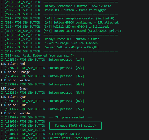
After flashing, power on, LED off, wait for button
1st press → Red
2nd press → Orange
...in sequence red→orange→yellow→green→cyan→blue→purple
7th press → Marquee effect (7-color ping-pong scan 3 cycles) → LED off → counter resets
Press again → Start from red
Log example:
xxxxxxxxxxI (282) RTOS_SEM_BUTTON: ============================================I (282) RTOS_SEM_BUTTON: Binary Semaphore + Button + WS2812 DemoI (282) RTOS_SEM_BUTTON: Press BOOT button 7 times to triggerI (292) RTOS_SEM_BUTTON: ============================================I (292) RTOS_SEM_BUTTON: [1/4] Binary semaphore created (initial=0).I (302) RTOS_SEM_BUTTON: [2/4] Button GPIO0 configured + ISR attached.I (312) RTOS_SEM_BUTTON: [3/4] WS2812 LED on GPIO48 initialized.I (312) RTOS_SEM_BUTTON: [4/4] Button task created (stack=3072, prio=3).I (322) RTOS_SEM_BUTTON: ============================================I (322) RTOS_SEM_BUTTON: Ready! Press BOOT button 7 times.I (332) RTOS_SEM_BUTTON: 1-Red 2-Orange 3-Yellow 4-GreenI (342) RTOS_SEM_BUTTON: 5-Cyan 6-Blue 7-Purple → MARQUEE!I (342) RTOS_SEM_BUTTON: ============================================I (352) main_task: Returned from app_main()I (125582) RTOS_SEM_BUTTON: Button pressed! [1/7]LED color: RedI (126072) RTOS_SEM_BUTTON: Button pressed! [2/7]LED color: OrangeI (126452) RTOS_SEM_BUTTON: Button pressed! [3/7]LED color: YellowI (127392) RTOS_SEM_BUTTON: Button pressed! [4/7]LED color: GreenI (128332) RTOS_SEM_BUTTON: Button pressed! [5/7]LED color: CyanI (130052) RTOS_SEM_BUTTON: Button pressed! [6/7]LED color: BlueI (131392) RTOS_SEM_BUTTON: Button pressed! [7/7]LED color: PurpleI (131592) RTOS_SEM_BUTTON: === 7th press reached! ===I (131992) RTOS_SEM_BUTTON: ╔══════════════════════════════╗I (131992) RTOS_SEM_BUTTON: ║ Marquee START (3 cycles) ║I (131992) RTOS_SEM_BUTTON: ╚══════════════════════════════╝I (134882) RTOS_SEM_BUTTON: >>> Marquee END <<<I (134882) RTOS_SEM_BUTTON: Counter reset. Press again...
7. FAQ
| Symptom | Cause | Solution |
|---|---|---|
| Button unresponsive | ISR not registered / Semaphore is NULL | Check gpio_isr_handler_add return value |
| One press triggers multiple responses | Debounce time too short | Increase DEBOUNCE_MS (recommended 50ms) |
Directly calling xSemaphoreGive in ISR | Not using FromISR version | Must use xSemaphoreGiveFromISR in ISR |
| Task never executes | Semaphore initial value wrong | Binary Semaphore initial value after creation = 0 |
| LED color too dark | Brightness value too low | Adjust each component in rainbow_colors (0-255) |
| Marquee effect too slow/fast | MARQUEE_STEP_MS inappropriate | Recommended 50~100ms |
| Press 7 times but doesn't enter marquee | Count logic problem | Check press_cnt >= TARGET_PRESSES |