Welcome to ROSMASTER M1 repository
10. Control serial port servos
10. Control serial port servos
10. Control serial port servos 10.1. Purpose of the experiment 10.2. Configuration pin information 10.3. Analysis of the experimental flow chart 10.4. core code explanation 10.5. Hardware connection 10.6. Experimental effect
10.1. Purpose of the experiment
Use the serial port function of STM32 to control the serial port servo and read the position of the serial port servo.
10.2. Configuration pin information
- Import the ioc file from the Serial project and name it Serial_Servo.
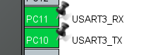
According to the schematic diagram, the serial port servo is connected to the serial port 3, PC10 and PC11 pins.
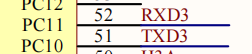
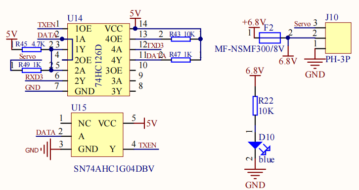
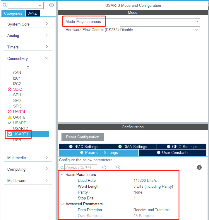
- Set serial port 3 to Asynchronous mode, and other parameters are shown in the figure below.
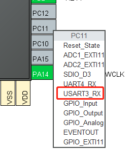
- Since the default serial port 3 pins are PB10 and PB11, and the serial port 3 of the expansion board schematic diagram is connected to PC10 and PC11, the serial port remapping function is required.
Click the PC11 pin first, and then select USART3_RX. After this operation, the pins of serial port 3 will be remapped to PC10 and PC11.
10.3. Analysis of the experimental flow chart
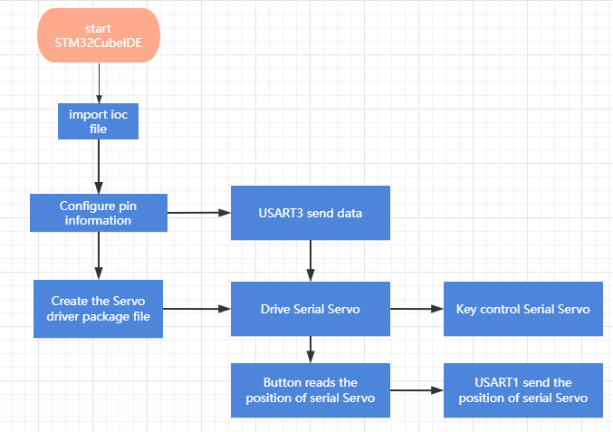
10.4. core code explanation
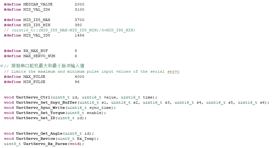
- Create new bsp_uart_servo.h and bsp_uart_servo.c, and add the following content in bsp_uart_servo.h:
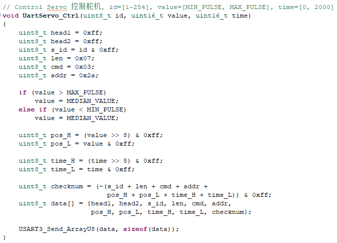
- Create the following content in the bsp_uart_servo.c file:
According to the communication protocol of the serial servo, create a new UartServo_Ctrl(id, value, time) to control the servo. The id corresponds to the ID of the servo to be controlled. If id=0xFE(254), all servos will be controlled. value indicates the position to which the control servo moves, time indicates the running time, before reaching the maximum speed, the shorter the time, the faster the running.
- The UartServo_Get_Angle() function requests the current position of the servo.

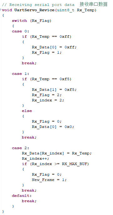
- The UartServo_Revice(Rx_Temp) function receives the serial port 3 data to determine whether it conforms to the serial port servo communication protocol. If it conforms to a frame of data, update the Rx_Data array and set New_Frame to 1.
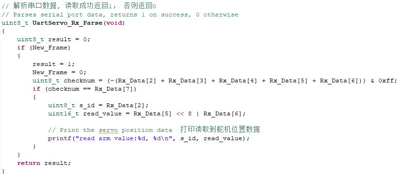
- Parse the data returned by the serial port servo, return 1 if the read is successful, and print the data, otherwise return 0.
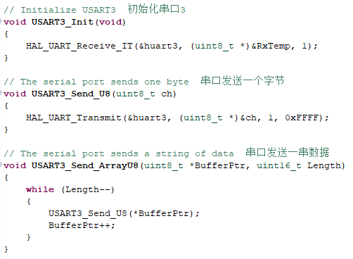
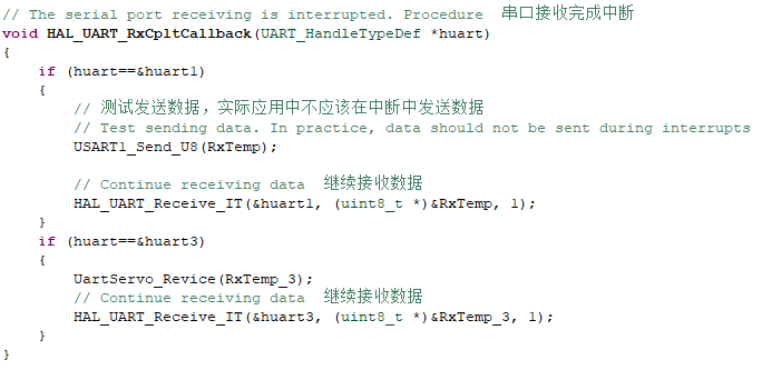
- Add the following functions related to writing and reading of serial port 3 in bsp_uart.c.
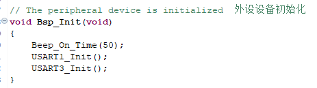
- Add the content of serial port 3 initialization in the Bsp_Init() function.
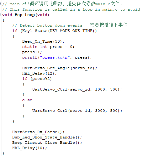
- In the Bsp_Loop() function, add the function of key reading and controlling the serial port servo.
10.5. Hardware connection
The serial port servo needs to be connected to the serial port servo port on the expansion board. The serial port servo port has the function of preventing reverse connection, and it can be inserted in the direction. Multiple serial servos can be cascaded. Due to the limited power supply current of the expansion board, do not connect too many servos. At present, six servos can be used normally.
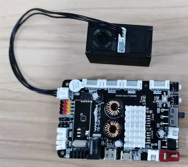
Because the power of the serial port servo is relatively large, the expansion board should not be powered by USB 5V directly, it needs to be powered by DC 12V.
10.6. Experimental effect
After the program is programmed, the LED light flashes every 200 milliseconds. Press the button multiple times, the serial servo will go back and forth between the 1000 position and the 3000 position, and return to the position data before the movement.