Welcome to ROSMASTER M3 PRO repository
4.Angular velocity calibration
Angular velocity calibration
Angular velocity calibration1. Course Content2. Preparation2.1 Content Description2.2 Start the Agent3. Run the case3.1 Startup Program3.2 Start calibration3.3 Writing calibration parameters to the chassis4. Source code analysis4.1 View the node relationship diagram4.2 Source code analysis
1. Course Content
Learn the function of robot angular velocity calibration
Run the angular velocity calibration program. After clicking Start on the visual interface, the robot chassis will begin to rotate and will stop when the error is less than the tolerance value.
2. Preparation
2.1 Content Description
This course uses the Jetson Orin NX as an example. For Raspberry Pi and Jetson Nano boards, you need to open a terminal and enter the command to enter the Docker container. Once inside the Docker container, enter the commands mentioned in this course in the terminal. For instructions on entering the Docker container, refer to the product tutorial [Configuration and Operation Guide] - [Enter the Docker (Jetson Nano and Raspberry Pi 5 users see here)]. For Orin and NX boards, simply open a terminal and enter the commands mentioned in this course.
2.2 Start the Agent
calibrate_angular Note: All test cases must start the docker agent first. If it has already been started, there is no need to start it again
Enter the command in the vehicle terminal:
sh start_agent.sh
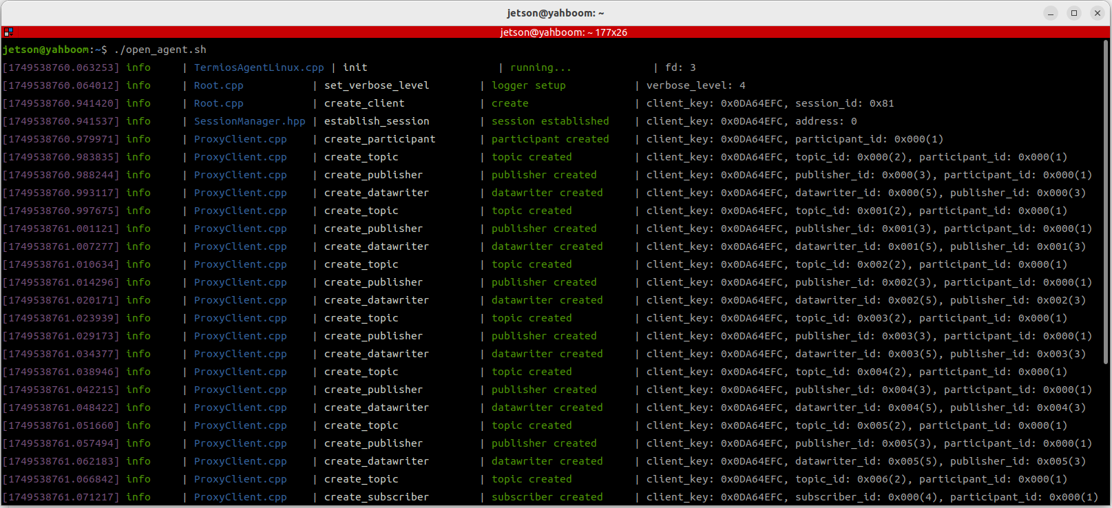
The terminal prints the following information, indicating that the connection is successful
3. Run the case
Notice:
- Jetson Nano and Raspberry Pi series controllers need to enter the Docker container first (please refer to the [Docker course chapter - Entering the robot's Docker container] for steps).
3.1 Startup Program
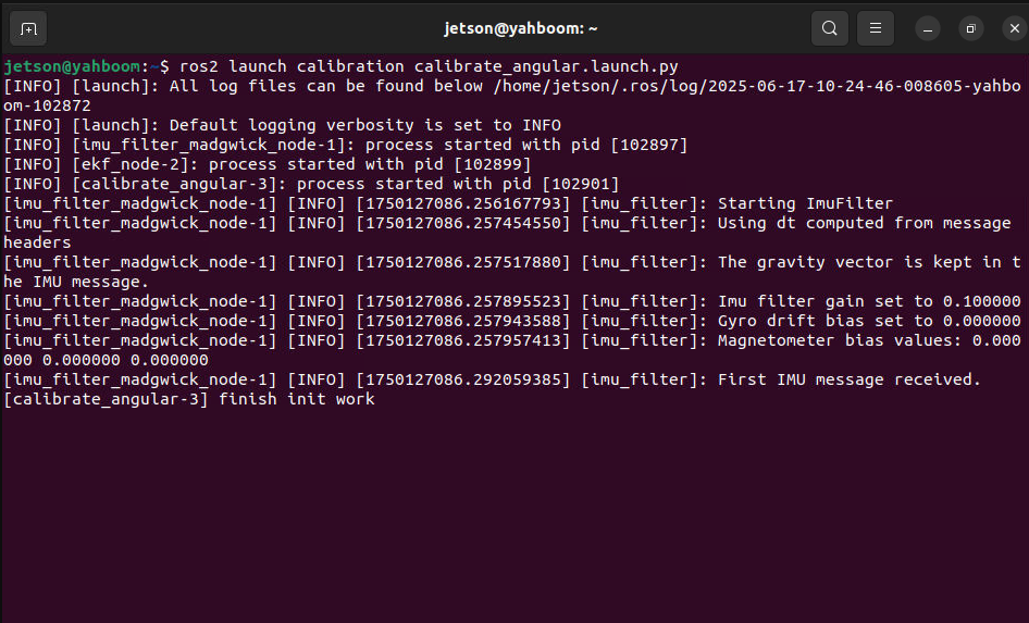
The vehicle computer opens the terminal and runs the angular velocity calibration node:
xxxxxxxxxxros2 launch calibration calibrate_angular.launch.py
Open the dynamic parameter adjuster in the virtual machine terminal and run:
xxxxxxxxxxros2 run rqt_reconfigure rqt_reconfigure
Click the calibrate_angular node in the node options on the left :
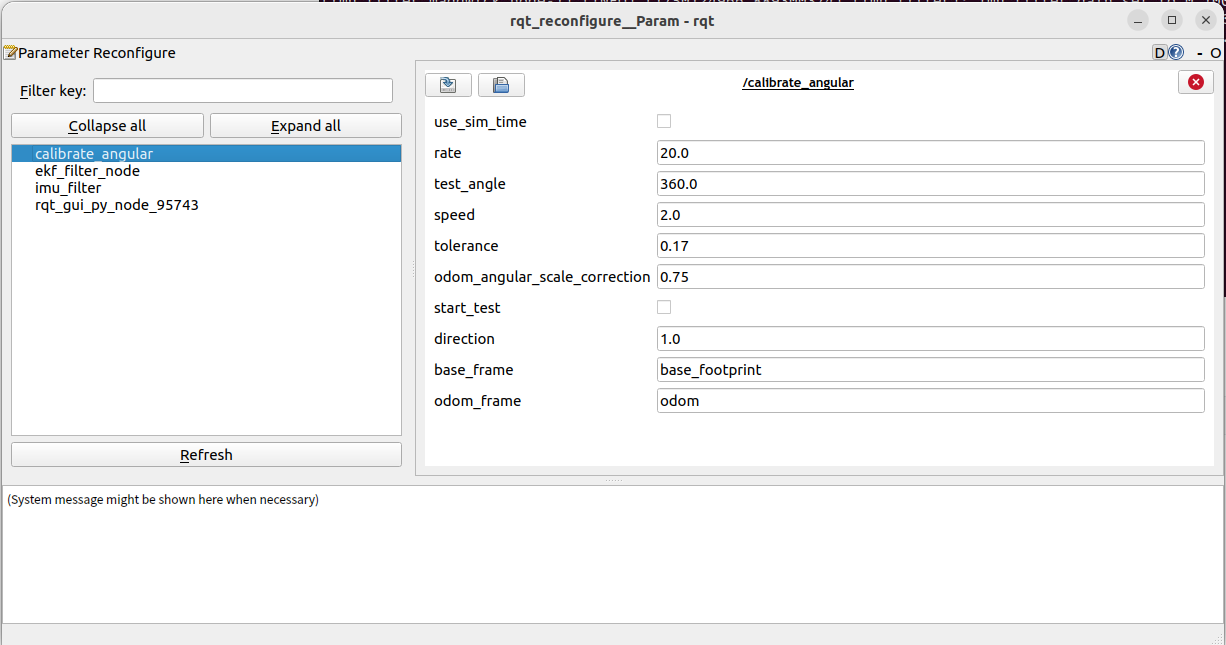
Note: The above nodes may not be present when you first open the application. Click Refresh to see all nodes. The calibrate_angular node displayed is the node for calibrating angular velocity.
Other parameters of the rqt interface are described as follows:
- test_angle: calibration test angle, here the test rotates 360 degrees;
- speed: angular velocity;
- Tolerance: the tolerance allowed for error;
- odom_angular_scale_correction: Linear velocity proportional coefficient. If the test result is not ideal, modify this value.
- start_test: test switch;
- base_frame: the name of the base coordinate system;
- odom_frame: The name of the odometry coordinate frame.
3.2 Start calibration
In the rqt_reconfigure interface, select the calibrate_angular node. There is a start_test node below . Click the box to the right of it to start calibration.
Click start_test to start calibration. The car will monitor the TF transformation of base_footprint and odom, calculate the theoretical rotation angle of the car, and issue a stop command when the error is less than tolerance.
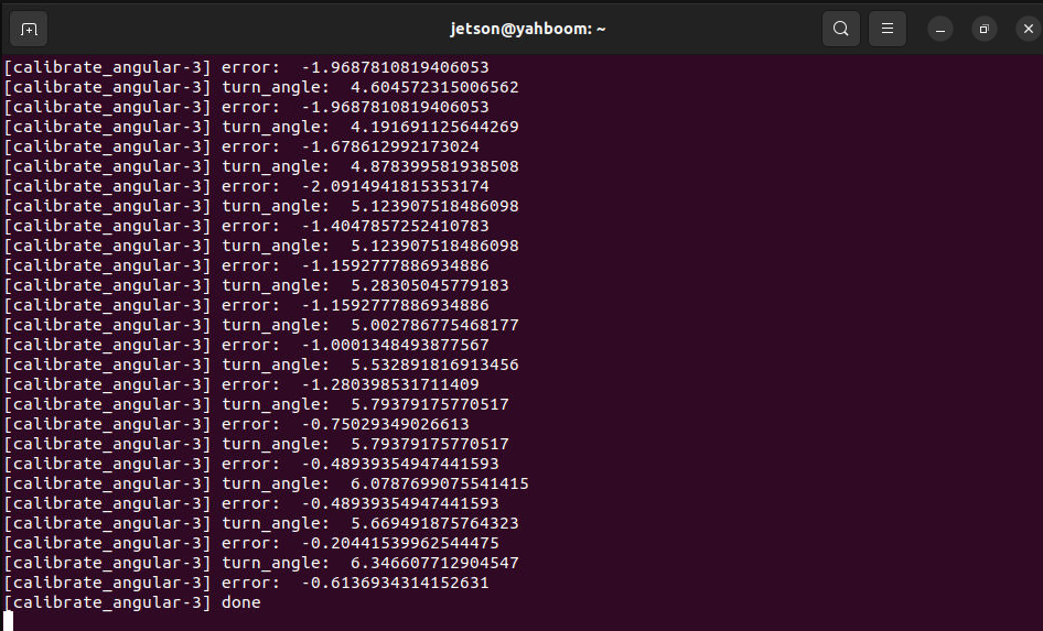
If the actual rotation angle of the car is not 360 degrees, then modify the odom_angular_scale_correction parameter in rqt. After modification, click a blank space, click start_test again, reset start_test, and then click start_test again to calibrate. Modifying other parameters is the same. You need to click a blank space to write the modified parameters. Record the last calibrated odom_angular_scale_correction parameter
3.3 Writing calibration parameters to the chassis
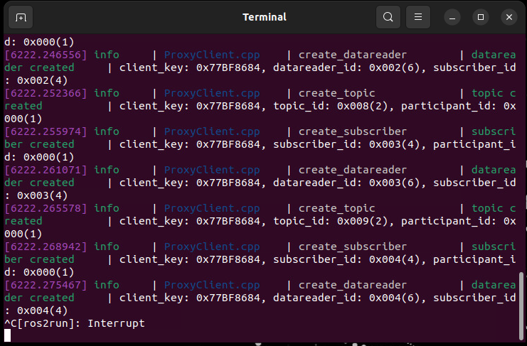
To write parameters to the chassis, you need to disconnect the chassis agent first. Press ctrl+c or directly close the chassis connection agent terminal.
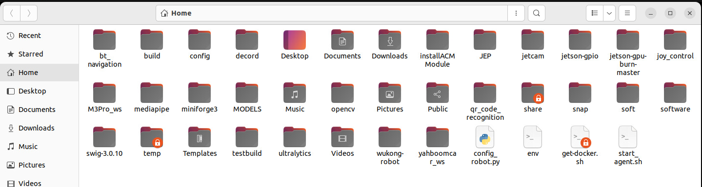
Open the config_robot.py file in the home directory of the vehicle
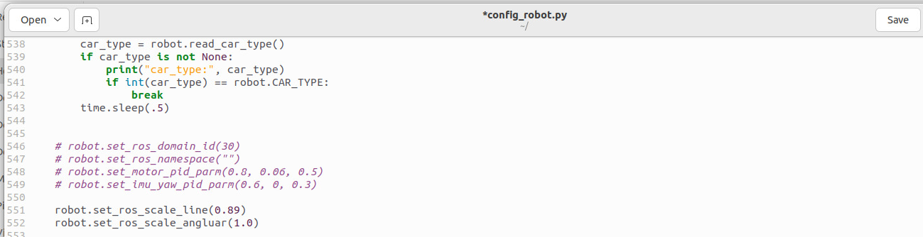
Uncomment line 552, enter the previous calibration coefficients in the brackets of robot.set_ros_scale_angluar(xx) , and click Save .
Open a terminal on the car and enter the command:
xxxxxxxxxxpython3 config_robot.py
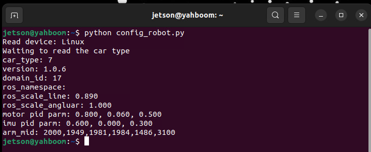
Wait for the parameter writing to be completed. The ros_scale_angluar:1.000 printed in the terminal information is the written parameter, and the chassis angular velocity calibration is completed.
4. Source code analysis
Source code path:
jetson orin nano, jetson orin NX host:
xxxxxxxxxx/home/jetson/M3Pro_ws/src/calibration/calibration/calibrate_angular.py
Jetson Orin Nano, Raspberry Pi host:
You need to enter docker first
xxxxxxxxxxroot/M3Pro_ws/src/calibration/calibration/calibrate_angular.py
4.1 View the node relationship diagram
Open a terminal on the virtual machine and enter the command:
xxxxxxxxxxros2 run rqt_graph rqt_graph
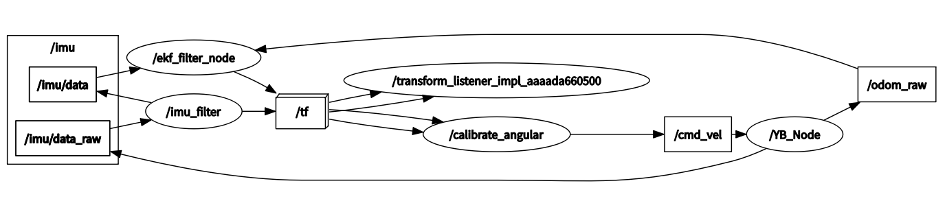
In the above node relationship diagram:
- The imu_filter node is responsible for filtering the original IMU data /imu/data of the chassis and publishing the filtered data /imu/data
- The /ekf_filter_node node subscribes to the chassis raw odometer /odom_raw and filtered IMU data /imu/data , performs data fusion and publishes to the /odom topic
- The calibrate_angular node monitors the TF transformation of odom->base_footprint and publishes the /cmd_vel topic to control the movement of the robot chassis.
4.2 Source code analysis
Among them, the implementation of monitoring tf coordinate transformation is the get_odom_angle method in the Calibrateangular class:
xdef get_odom_angle ( self ): try : now = rclpy . time . Time () rot = self . tf_buffer . lookup_transform ( self . base_frame , self . odom_frame , now , timeout = rclpy . duration . Duration ( seconds = 1.0 )) cacl_rot = PyKDL . Rotation . Quaternion ( rot . transform . rotation . x , rot . transform . rotation . y , rot . transform . rotation . z , rot . transform . rotation . w ) #print("cacl_rot: ",cacl_rot) angle_rot = cacl_rot . GetRPY ()[ 2 ] #print("angle_rot: ",angle_rot) except ( LookupException , ConnectivityException , ExtrapolationException ): # self.get_logger().info('transform not ready') returnThe on_timer (timer callback function) method in the Calibrateangular class is used to determine the rotation angle of the robot chassis and control the chassis movement:
xxxxxxxxxxdef on_timer ( self ): self . start_test = self . get_parameter ( 'start_test' ). get_parameter_value (). bool_value self . odom_angular_scale_correction = self . get_parameter ( 'odom_angular_scale_correction' ) . get_parameter_value () . double_value self . test_angle = self . get_parameter ( 'test_angle' ) . get_parameter_value () . double_value self . test_angle = radians ( self . test_angle ) # Convert angle to radians self . speed = self . get_parameter ( 'speed' ). get_parameter_value (). double_value move_cmd = Twist () self . test_angle *= self . reverse #self.test_angle *= self.reverse #self.error = self.test_angle - self.turn_angle if self . start_test : self . error = self . turn_angle - self . test_angle if abs ( self . error ) > self . tolerance : #move_cmd.linear.x = 0.2 move_cmd . angular . z = copysign ( self . speed , self . error ) #print("angular: ",move_cmd.angular.z) self . cmd_vel . publish ( move_cmd ) self . odom_angle = self . get_odom_angle () self . delta_angle = self . odom_angular_scale_correction * self . normalize_angle ( self . odom_angle - self . first_angle ) #print("delta_angle: ",self.delta_angle) self . turn_angle += self . delta_angle print ( "turn_angle: " , self . turn_angle , flush = True ) #self.error = self.test_angle - self.turn_angle print ( "error: " , self . error , flush = True ) self . first_angle = self . odom_angle #print("first_angle: ",self.first_angle) else : self . error = 0.0 self . turn_angle = 0.0 print ( "done" , flush = True )