Welcome to ROSMASTER M3 PRO repository
2. OpenClaw robotic arm tracking and grasping
OpenClaw Robotic Arm Tracking And Grasping
OpenClaw Robotic Arm Tracking And Grasping1. Course ContentLearning Objectives2. Preparation3. Robotic Arm Grasping Target Object Case4. Source Code Analysis① pick() — Grasp Object② _get_grasp_point() — Get Grasp Point Coordinates (Internal Method)5. Parameter Debugging6. FAQ6.1 How to Adjust When the Grasp Position Is Inaccurate and Deviates from the Ideal Grasp Point?6.2 How to Adjust grasp_offset6.3 How to Replace and Test the Vision Model If Positioning Is Inaccurate?
1. Course Content
Learning Objectives
- Learn to adjust key parameters such as
grasp_offsetandplace_offsetto optimize grasping accuracy and stability - Develop the ability to analyze the causes of grasping deviations, and diagnose and resolve visual recognition and depth loss issues
2. Preparation
- Start the MicroROS chassis agent (skip if already started)
sh start_agent.sh
- Start odometry, tf, robotic arm assistant, camera node and other nodes
xxxxxxxxxxros2 launch m3pro_bringup car_base.launch.py- Start the MCP service
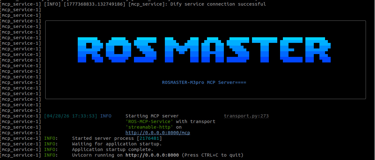
xxxxxxxxxxros2 launch m3pro_bringup mcp_service.launch.py
- If you need voice reply, you need to additionally start openclaw_bridge, otherwise you can skip
xxxxxxxxxxros2 run multi_brains_pre openclaw_bridge
3. Robotic Arm Grasping Target Object Case
[!TIP]
- You can write commands according to your own needs. The following is a case demonstration. Choose any interaction method. Here we use the web page WebChat as an example.
[!IMPORTANT]
- The block demonstrated here for grasping is a 4x4x4cm wooden block. Tracking and grasping can pick up any target object. Since the servo has no torque feedback, the grasping closure angle of the gripper needs to be specified through parameters. If the gripper grasps too loosely or too tightly, fine-tuning can be done through parameters.
- Grasp the orange block in front of you
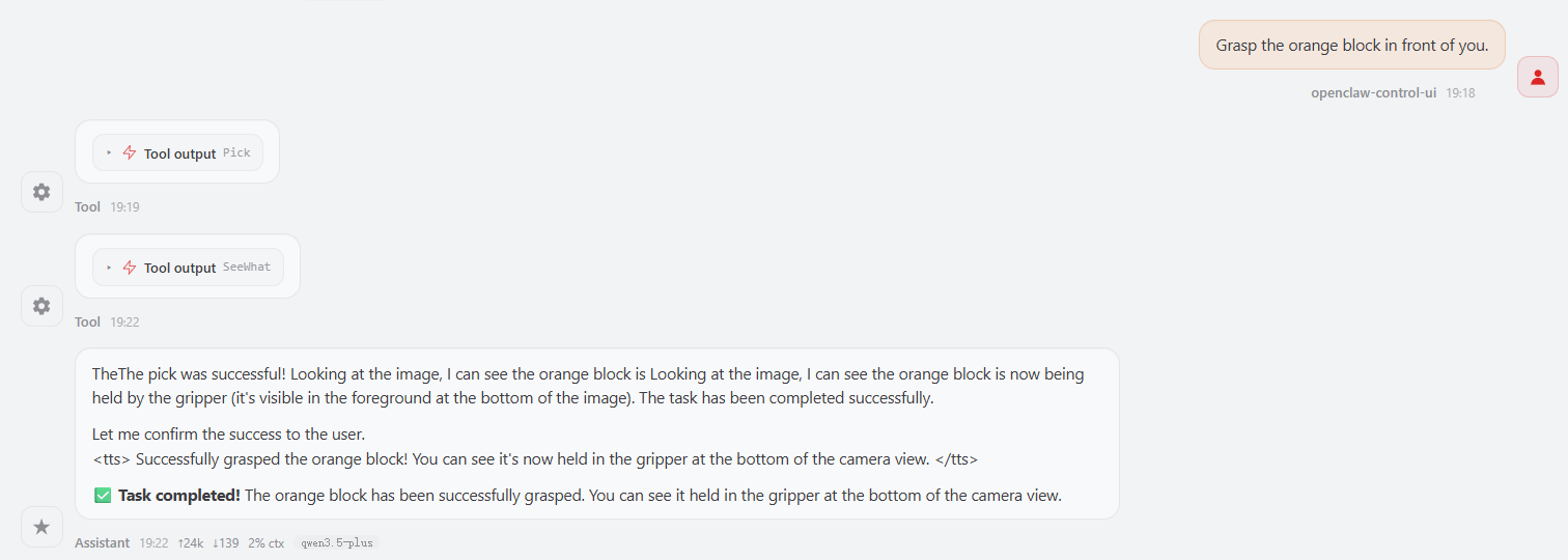
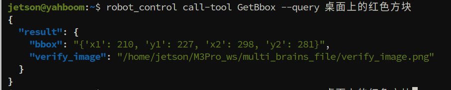
- OpenClaw calls GetBbox to obtain the outer bounding box of the target. This interface automatically generates a verification image to verify whether the Dify vision model has selected the correct area. Image path:
xxxxxxxxxx$HOME/M3Pro_ws/multi_brains_file/verify_image.png
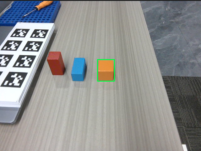
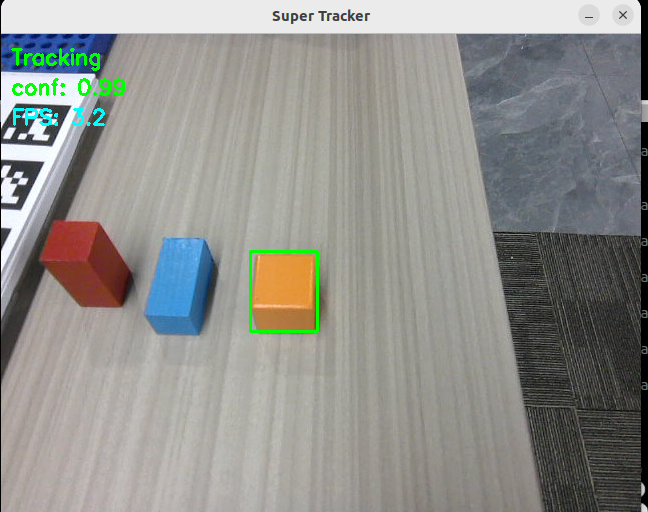
- The figure below shows the tracking process of the grasping target. The robot chassis will first adjust the chassis position to ensure the target is within the grasping range of the robotic arm.
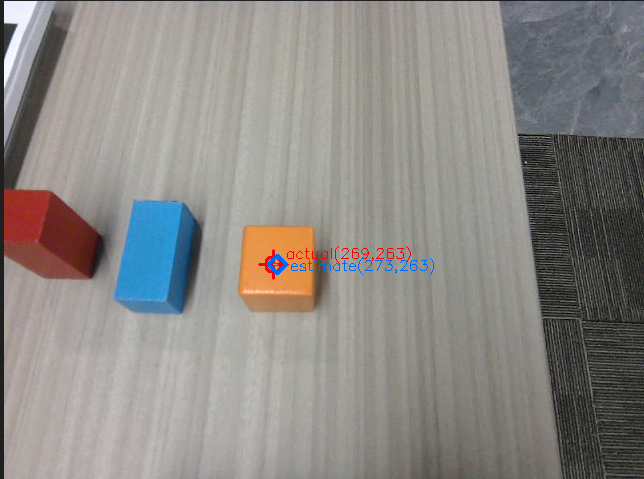
- After the chassis adjustment is completed, the grasping point will be obtained as shown below. The program will automatically draw the image of the grasping point for debugging and verifying whether the grasping point is accurate. The image path is:
xxxxxxxxxx$HOME/M3Pro_ws/multi_brains_file/grasp_point_image.png
- Object grasping process
xxxxxxxxxx┌─────────────┐│ Observe ││ Environment │└──────┬──────┘│▼┌─────────────┐│ Get Target ││ Bounding Box│└──────┬──────┘│▼┌─────────────┐│ Track Target│└──────┬──────┘│▼┌─────────────┐│ Adjust ││ Chassis ││ Position │└──────┬──────┘│▼┌─────────────┐│ Grasp Target│└──────┬──────┘│▼┌─────────────┐│ Check If ││ Target ││ Is Grasped │└─────────────┘
Target grasping skills
- OpenClaw controls the robot to grasp the target object by first reading the robotic arm grasping skills, following the SOP workflow.
- Robotic arm grasping skill reference: [08-OpenClaw Skills Development]
[!IMPORTANT]
- In [03-OpenClaw Development][02-OpenClaw Robotic Arm Tracking And Grasping], OpenClaw will first track the target before grasping it.
4. Source Code Analysis
- Source code path:
xxxxxxxxxx$HOME/M3Pro_ws/src/multi_brains_pre/multi_brains_pre/action_controller.py
The core functional functions of the grasping program are all defined in the ActionController class. After being registered through the MCP Tool interface, they can be called by OpenClaw. The following is an explanation of each key function's source code.
① pick() — Grasp Object
xxxxxxxxxxdef pick(self, x1:int, y1:int, x2:int, y2:int) -> list[bool, str]: """Pick up item""" # Step 1: Start target tracking result = self.start_track_client.call( StartTrack.Request(x1=x1, y1=y1, x2=x2, y2=y2)) # Step 2: Adjust grasping pose if not self._adjust_grasp_pose(): return [False, "Failed to adjust grasp pose"] # Step 3: Get grasp point result = self._get_grasp_point() # Step 4: Execute grasp self._grasp(grasp_x=result[1], grasp_y=result[2], grasp_z=result[3], grasp_pitch=self.grasp_offset[3]) # Step 5: Auto backward self.move_by_odom(direction='backward', distance=self.auto_back_dist) return [True, ""]Process description:
- Start tracking: Based on the target bounding box (x1, y1, x2, y2) detected by vision, call the
/start_trackservice to start Smart Tracker target tracking. _adjust_grasp_pose(): An internal loop that executes the "align camera → measure object 3D pose → move chassis" process until the target is within grasping range._get_grasp_point(): Call/get_box_centerto get the pixel coordinates of the grasp point, then combine with the 3D pose service to convert to spatial coordinates. See below for detailed source code and explanation._grasp()(internal method): Solve the 6 joint angles through inverse kinematics (IK), publish to thearm6_jointstopic to drive the robotic arm, then close the gripper.- Auto backward: After grasping is complete, move backward by the
auto_back_distdistance to avoid collisions and entering costmap obstacle areas.
② _get_grasp_point() — Get Grasp Point Coordinates (Internal Method)
xxxxxxxxxxdef _get_grasp_point(self) -> list: """获取抓取点的3D空间坐标""" # Step 1: Ensure box_center service is available if not self.box_center_client.wait_for_service(timeout_sec=8.0): return [False, "get grasp point service not available"] # Step 2: Capture the current frame, get grasp point detection result self.SeeWhat() response = self.box_center_client.call(GetBoxCenter.Request()) if not response.success: return [False, response.message] # Step 3: Draw grasp point verification image (for debugging) image = cv2.imread(self.image_path) ax, ay = int(response.actual_center[0]), int(response.actual_center[1]) ex, ey = int(response.estimate_center[0]), int(response.estimate_center[1]) # Draw red crosshair (actual) and blue diamond (estimate), connect the two points cv2.imwrite(self.grasp_point_path, image) # Step 4: Prefer estimate_pose, calculate pixel offset compensation to 3D coordinates if response.estimate_pose is not None: offset_x = (ax - ex) / 1000 # pixel offset → meters offset_y = (ay - ey) / 1000 if offset_x < 0.02: offset_x = 0 if offset_y < 0.02: offset_y = 0 grasp_x = response.actual_pose.position.x + offset_y # image vertical direction grasp_y = response.actual_pose.position.y + offset_x # image horizontal direction grasp_z = response.actual_pose.position.z return [True, grasp_x, grasp_y, grasp_z] # Step 5: Fallback to actual_pose return [True, response.actual_pose.x, response.actual_pose.y, response.actual_pose.z]Code explanation:
- Based on engineering experience, a grasp center estimation algorithm is proposed. When most of the depth data of the target object is missing due to environmental lighting, it can still estimate the 3D coordinates of the grasping target center. Due to space limitations, the theory is not derived; only the program source code is explained.
- Dual-center mechanism: The returned result includes
actual_center(actual detection center) andestimate_center(algorithm estimated center). The pixel offset between the two is used to compensate for the error in 3D spatial coordinates. - Verification image: Automatically draws a red crosshair (actual) and a blue diamond (estimate) onto
grasp_point_image.pngfor debugging whether the grasp point is accurate. - Priority strategy:
estimate_posetakes precedence overactual_posebecause it combines visual detection and grasp center point estimation algorithm, resulting in higher accuracy. - Offset compensation:
(ax-ex)/1000approximately converts the pixel coordinate difference into an offset in meters, compensating the grasp coordinates. Here, only the pixel unit is proportionally scaled to the actual unit.
5. Parameter Debugging
- Parameter file path:
xxxxxxxxxx$HOME/M3Pro_ws/src/m3pro_bringup/config/common.yaml
The following is the correspondence table between parameters and code:
| Parameter | Code Usage Location | Function Description |
|---|---|---|
GraspKeepPose | _grasp() → self.GraspKeepPose | Joint angle posture maintained by the robotic arm after grasping |
InitArmPose | InitArmPose() → self.init_arm_pose | Target joint angles for restoring the robotic arm to its initial posture |
grasp_distance | _adjust_grasp_pose() → self.grasp_distance[0] | Desired distance between chassis and target during grasping (x direction), used to determine if chassis movement is needed |
grasp_offset | _grasp() → self.grasp_offset[0]/[1]/[2]/[3] | Grasp position offset [x, y, z, grasp angle], used for fine-tuning grasp coordinates |
auto_back_dist | pick(), place() → self.auto_back_dist | Auto backward distance after grasp/place completion to avoid collisions and entering costmap forbidden zones |
target_circle | GetPlacePoint() / _get_pick_target_pose() → self.target_circle | Circular area sampling radius (pixels) used for calculating 3D pose when obtaining target point coordinates |
xxxxxxxxxxmcp_service ros__parameters #action_controller——Arm GraspKeepPose901253090140 #Robotic arm grasp keep posture, 140 is gripper opening angle, 0-180, larger value means tighter grip grasp_distance0.265 0.0 0.0 # [x, y, yaw] place_distance0.39 0.00.45 0.25 #Place position and tolerance detection grasp_offset0.0150.015-0.032.0 # Grasp offset x,y,z,grasp angle place_offset-0.010.000.051.3 #Place position offset auto_back_dist0.13 # Auto backward distance, unit: meters, automatically moves backward a distance after grasping and placing to avoid collisions and entering costmap forbidden zones #odom tf_tolerance 0.5 # TF transform tolerance, unit: seconds linear_speed_factor0.5 # Linear speed factor angular_speed_factor0.1 # Angular speed factor odom_linear_speed0.08 odom_angular_speed0.5 odom_position_tolerance0.005 odom_angle_tolerance0.05 odom_timeout30.0 target_circle 10 # Circular area radius when obtaining target point coordinates, unit: pixels #auto back enable_auto_backTrue # Whether to enable auto backward function[!IMPORTANT]
- The auto backward function after grasping (enable_auto_back) is designed to avoid colliding with map edges when combined with navigation. If you need to disable auto backward, set enable_auto_back to False in the parameter file. The auto backward function in subsequent courses (garbage grasping, machine code grasping, placing) is all controlled by this parameter and will not be repeated in later lessons.
6. FAQ
6.1 How to Adjust When the Grasp Position Is Inaccurate and Deviates from the Ideal Grasp Point?
Check in order:
Is the Dify model's bounding box selection of the target object accurate?
- If inaccurate, replace the vision model in Dify.
Is the grasp point obtained before grasping accurate?
- If the grasp point deviates too far from the object center, it means the depth camera is heavily affected by ambient lighting and the target object has no depth data at all. The grasp center estimation algorithm cannot estimate the 3D position of the target grasp point. Change the ambient lighting.
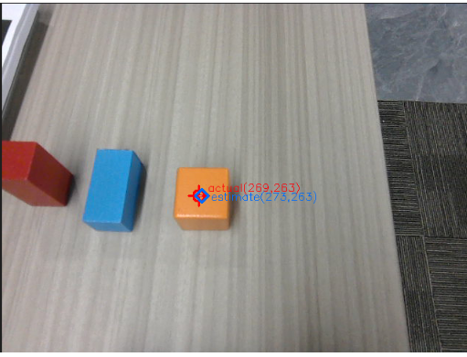
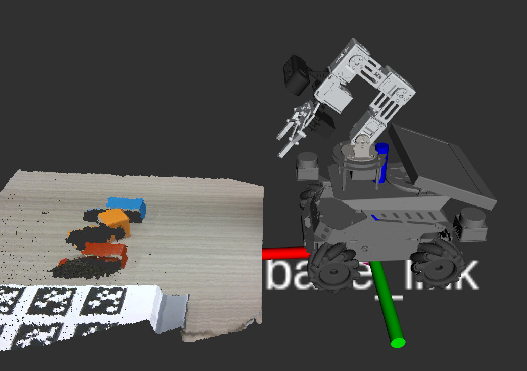
If the grasp point is accurate (e.g., the grasp point is at the center of the grasped object in the image below) but there is a slight offset during grasping, it may be caused by mechanical error of the robotic arm. Refer to Section 5.2 Grasp Parameter Analysis and adjust grasp_offset. The offset follows the robot's right-hand coordinate system. Increase or decrease the grasp offset appropriately.
6.2 How to Adjust grasp_offset
Parameter description of grasp_offset:
The grasp_offset parameter format is [x offset, y offset, z offset, grasp angle], with a default value of [0.015, 0.015, -0.03, 2.0].
Adjustment principles:
X-axis offset (forward/backward direction)
- Positive value: grasp point forward (away from the robot body)
- Negative value: grasp point backward (toward the robot body)
Y-axis offset (left/right direction)
- Positive value: grasp point to the left (left side in the robot's forward direction)
- Negative value: grasp point to the right (right side in the robot's forward direction)
Z-axis offset (up/down direction)
- Positive value: grasp point upward
- Negative value: grasp point downward
- Adjustment scenario: used when grasping too high or too low, often to compensate for the height difference between the gripper and the object surface
Grasp angle (gripper rotation angle)
- Unit: radian (rad)
- Adjustment scenario: adjust when needing to grasp the object from a specific angle; not recommended to change
Adjustment steps:
- Perform a grasping operation and record the deviation direction between the actual grasp position and the ideal position.
- Determine the direction and sign to adjust based on the right-hand coordinate system principle.
- Modify the corresponding offset parameter in
common.yaml. The change takes effect immediately after saving. - Restart the MCP service to apply the parameters:
ros2 launch m3pro_bringup mcp_service.launch.py
Example scenario:
xxxxxxxxxxScenario: When grasping the orange block, the robotic arm always deviates about 1cm to the rightAnalysis: Deviation to the right in the Y-axis direction, needs compensation in the positive direction (left)Adjustment: Change the y value of grasp_offset from 0.015 to 0.025Verification: Re-test grasping and observe if it improves
- Right-hand coordinate system
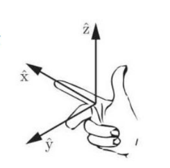
- Chassis coordinate system direction
6.3 How to Replace and Test the Vision Model If Positioning Is Inaccurate?
Enter the robot's IP in the browser to access the Dify management page
- Username: yahboom@163.com
- Password: yahboom123
Find the Robot Vision application
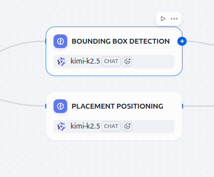
- Bounding Box Detection and Placement Positioning are the visual positioning models:
- Bounding Box Detection is used for bounding box positioning based on natural language descriptions, used in visual grasping and tracking tasks to locate the initial bounding box of the target in the image.
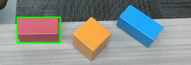
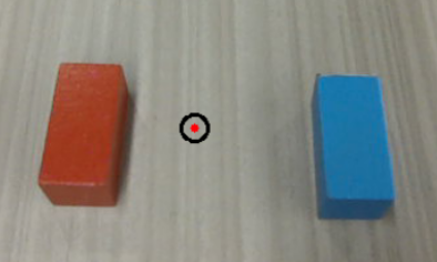
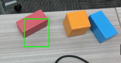
Example: Red block on the table
- The green box below is the visualization result of the object's bounding box coordinates given by the vision model based on the natural language description.
Placement Positioning is used for target point positioning based on natural language descriptions, commonly used in robotic arm placement tasks to find the target position to place.
Example: Between the red block and the blue block
- The green box below is the visualization result of the target point given by the vision model based on the natural language description.
- You can use the CLI tool in the terminal to test whether the current model selected in Dify has accurate visual positioning. verify_image is the path to the visual verification image.
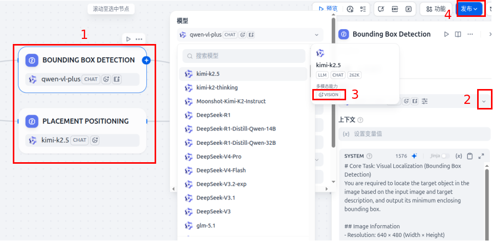
- If the visual positioning of the currently used model is inaccurate, you can replace the vision model.
- Click the corresponding card — scroll down and select an available vision model from the model list (vision models will have a VISION tag) — finally click Publish to save the changes.
[!TIP]
- Recommended vision models: QwenVL-Max series, Kimi-k2.5 series, etc.