Welcome to ROSMASTER M3 PRO repository
3. OpenClaw robotic arm fixed-point placement
OpenClaw Robotic Arm Precision Placement
OpenClaw Robotic Arm Precision Placement1. Course ContentCourse OverviewLearning Objectives2. Preparation3. Robotic Arm Precise Placement Use Case4. Source Code Analysis4.1 GetPlacePoint() — Obtaining Placement Point Coordinates4.3 _place() — Execute Placement Action (Internal Method)5. Parameter Debugging6. Functionality Q&A6.1 How do I adjust the distance between the robot chassis and the target placement point?6.2 How do I adjust the placement position if it is inaccurate? Checklist (in order):
1. Course Content
Course Overview
This course explains the complete technical process of using OpenClaw to control an M3Pro robot to achieve precise placement of the robotic arm. The course covers all aspects from natural language understanding, visual point recognition, 3D coordinate transformation to precise robotic arm placement, including Dify visual agent invocation and inverse kinematics (IK) solving.
Learning Objectives
Master the technical workflow for using OpenClaw to control a robotic arm for precise object placement via natural language instructions.
Understand the role of the Dify Vision Agent in identifying target locations and how to invoke it.
Learn how to use the
GetPlacePointtool to retrieve the 3D coordinates of a placement target and verify if it falls within the robotic arm's reachable workspace.
2. Preparation
Start the MicroROS chassis agent (skip this step if it is already running).
sh start_agent.sh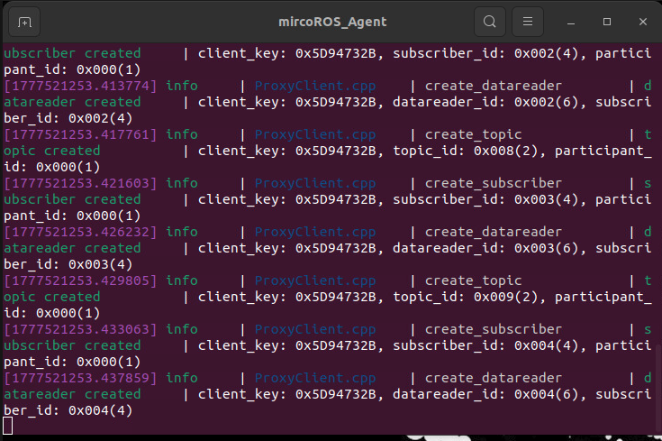
Launch the odometry, TF, robotic arm auxiliary, camera, and other relevant nodes.
xxxxxxxxxxros2 launch m3pro_bringup car_base.launch.pyStart the MCP service.
xxxxxxxxxxros2 launch m3pro_bringup mcp_service.launch.py
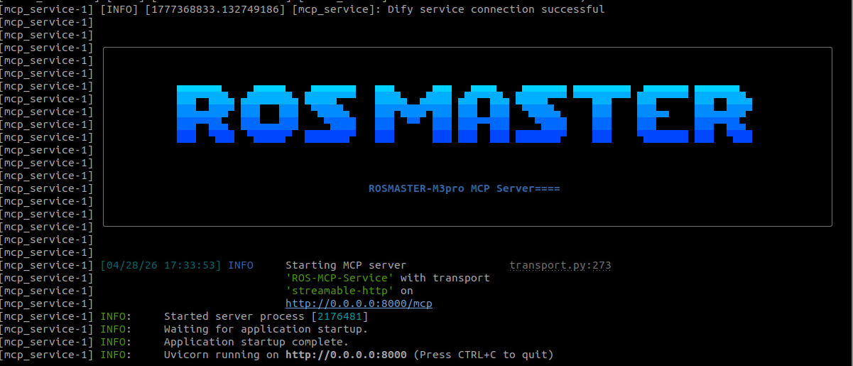
If you require voice feedback, you must additionally launch the
openclaw_bridge; otherwise, this step can be skipped.
xxxxxxxxxxros2 run multi_brains_pre openclaw_bridge
3. Robotic Arm Precise Placement Use Case
Tip
You may formulate commands according to your specific needs; the following serves as a demonstration. You may choose any interaction method you prefer; this example uses the WebChat interface for the demonstration.
| Command | Parameters | Function |
|---|---|---|
| GetPlacePoint | --query | Locates the coordinates of a placement target and checks if it lies within the robotic arm's reachable workspace. |
| Place | --place-x, --place-y, --place-z | Places an object at the specified coordinate position. |
The
Placetool provides the capability to place an object at a specific location within the robot's camera field of view, based on a natural language description. For example: Place the grasped orange block between the red and blue blocks located in front of you.
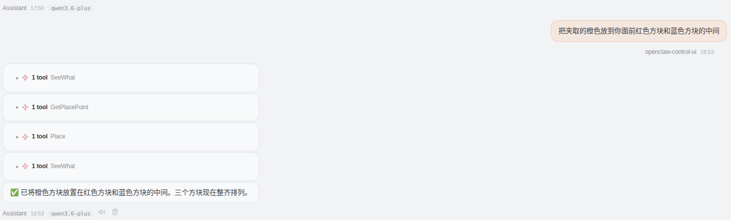
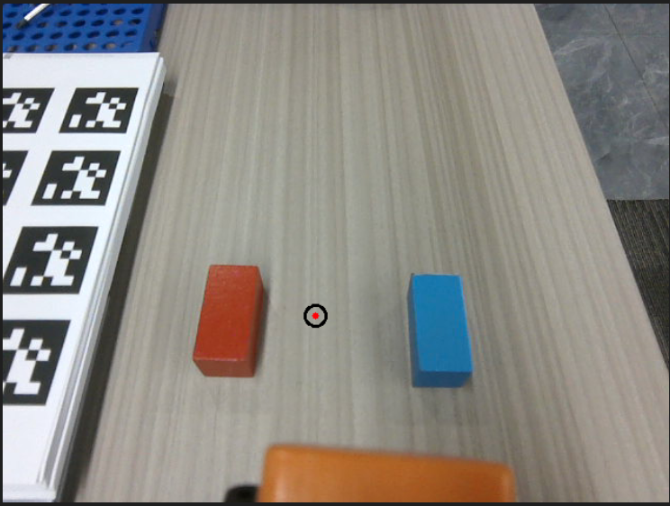
When obtaining a placement point, a verification image is automatically generated to facilitate debugging and to verify the accuracy of the placement coordinates. The image path is:
xxxxxxxxxx$HOME/M3Pro_ws/multi_brains_file/place_verify_image.png
4. Source Code Analysis
Source Code Path
xxxxxxxxxx$HOME/M3Pro_ws/src/multi_brains_pre/multi_brains_pre/action_controller.py
4.1 GetPlacePoint() — Obtaining Placement Point Coordinates
xxxxxxxxxxdef GetPlacePoint(self, query: str) -> list[bool, str]: """Retrieve the 3D spatial coordinates of the placement point"""# Step 1: Capture the current scene save_result = self.SeeWhat() if not save_result[0]: return [False, f"SeeWhat error:{save_result[1]}", ""] # Step 2: Apply Grid Overlay and Invoke Dify Vision Agent for Analysis img = draw_grid_overlay(image=cv2.imread(self.image_path), grid_size=20) cv2.imwrite(self.grid_images_path, img) agent_result = self._request_dify_agent(query, self.grid_images_path, TYPE="POINT") if not agent_result[0]: return [False, f"Dify Agent error:{agent_result[1]}", ""] # Step 3: Retrieve pixel coordinates and check for the presence of the target. point_data = agent_result[1].get("point", {}) x, y = point_data.get("x"), point_data.get("y") if x == -1 and y == -1: return [False, "目标点不存在于画面中", ""] # Step 4: Draw point verification image (for debugging purposes) img = cv2.imread(self.image_path) cv2.circle(img, (x, y), self.target_circle, (0, 0, 0), 2) # Circular Marker cv2.circle(img, (x, y), 3, (0, 0, 255), -1) # Center Red Dot cv2.imwrite(self.place_verify_image_path, img) # Step 5: Convert pixel coordinates to spatial coordinates using the 3D Pose Service. request = GetTargetPose.Request(x=float(x), y=float(y), radius=self.target_circle) result = self.get_pose_client.call(request) if not result.success: return [False, str(result.message), ""] point = str({"x": round(result.pose.position.x, 2), "y": round(result.pose.position.y, 2), "z": round(result.pose.position.z, 2)}) # Step 6: Check if within the robotic arm's workspace if result.pose.position.x <= self.place_distance[2] and \ result.pose.position.y <= self.place_distance[3]: msg = "✅ 目标点在工作范围内" else: msg = "❌ 目标点超出工作范围" return [True, msg, point]Process Description:
First, capture the current scene and overlay a 20px grid reference (to facilitate positioning by the Dify Vision Model).
Invoke the Dify Vision Agent to parse natural language instructions and return the pixel coordinates (x, y) for the placement location.
If
(-1, -1)is returned, it indicates that the target is not present in the scene; an error is returned immediately.Generate a point verification image saved as
place_verify_image.png, using a black circle to mark the target area and a red dot to mark its center, to aid in debugging.Convert the pixel coordinates into 3D spatial coordinates using the
get_target_poseservice.Use
place_distance[2](x-axis upper limit) andplace_distance[3](y-axis upper limit) to determine whether the target point lies within the robotic arm's workspace.
4.2 place() — Placing Items
xdef place(self, place_x: float, place_y: float, place_z: float) -> list[bool, str]: """The robotic arm places the object to the target position.""" # Step 1: Execute placement action self._place(place_x, place_y, place_z, place_pitch=self.place_offset[3])
# Step 2: Automatic Backtrack self.move_by_odom(direction='backward', distance=self.auto_back_dist) self.get_logger().info("Place object complete") return [True, ""]Process Description:
Invoke Internal Placement Method: Pass the target placement coordinates (
place_x,place_y,place_z) to the_place()method, along with the configured placement angleplace_offset[3](pitch angle).Automatic Retraction: Upon completion of the placement, retract by a distance of
auto_back_distto prevent collisions between the robotic arm and the placement platform.
4.3 _place() — Execute Placement Action (Internal Method)
xxxxxxxxxxdef _place(self, place_x, place_y, place_z,            place_roll=0.0, place_pitch=0.0, place_yaw=0.0):   # Step 1: Construct the inverse kinematics solve request, applying the placement offset.    request = ArmKinemarics.Request()    request.tar_x = place_x + self.place_offset[0]    request.tar_y = -(place_y + self.place_offset[1])  # Invert Y-Axis (Coordinate System Transformation)    request.tar_z = place_z + self.place_offset[2]    request.kin_name = "ik"    request.roll = place_roll    request.pitch = place_pitch    request.yaw = place_yaw
    # Step 2: Call the Inverse Kinematics Solver    response: ArmKinemarics.Response = self.arm_kin_client.call(request)    self.get_logger().info(f"place IK-pose: {response}")
    # Step 3: Extract Joint Angles and Control Robot Arm Movement    joints = [0, 0, 0, 0, 0, 0]    joints[0] = int(response.joint1)    joints[1] = int(response.joint2)    joints[2] = int(response.joint3)    joints[3] = int(response.joint4)    joints[4] = int(response.joint5)    joints[5] = self.GraspKeepPose[5]  # Joint 6 maintains the gripping posture angle.    self._pubSix_Arm(joints)    time.sleep(4.0)  # Waiting for the robotic arm to reach the target position        # Step 4: Release the Gripper Jaws    self.SingleJoint_pub.publish(ArmJoint(id=6, joint=0, time=1500))    time.sleep(2.0) # Wait for Object Release        # Step 5: Restore the robotic arm to its initial pose.    self._pubSix_Arm(self.init_arm_pose)
Code Explanation:
Offset Superposition: The
place_offset(x/y/z) is superimposed onto the target placement coordinates to fine-tune the exact placement position.Inverse Kinematics Solution: Calls the
/get_kinematicsservice (withkin_name="ik") to calculate the six joint angles required to achieve the target pose.Joint Control: Publishes the six joint angles to the
arm6_jointstopic via_pubSix_Arm(), driving the robotic arm to move to the designated placement location.Object Release: Controls the 6th joint (the gripper) to open (joint=0), thereby releasing the grasped object.
Pose Recovery: Upon completion of the placement task,
_pubSix_Arm(self.init_arm_pose)is called to restore the robotic arm to its initial pose, preventing interference with subsequent operations.
Key Parameter Descriptions:
place_offset[0]: X-axis offset; adjusts the forward/backward position of the placement point.place_offset[1]: Y-axis offset; adjusts the left/right position of the placement point.place_offset[2]: Z-axis offset; typically set to a positive value (e.g., 0.05m) to ensure the object is released slightly above the target surface during placement.place_offset[3]: Placement pitch angle; controls the orientation of the gripper during placement (default: 1.3 rad).
5. Parameter Debugging
Parameter File Path:
xxxxxxxxxx$HOME/M3Pro_ws/src/m3pro_bringup/config/common.yaml
The following table outlines the correspondence between the parameters and the code:
| Parameter | Location in Code | Function Description |
|---|---|---|
place_distance | GetPlacePoint() → self.place_distance[2]/[3] | XYZ coordinates for the placement position, and tolerance check for the robot arm's workspace ([2] is the X upper limit; [3] is the Y upper limit). |
place_offset | _place() → self.place_offset[0]/[1]/[2]/[3] | Placement position offset, used for fine-tuning the placement coordinates. |
auto_back_dist | pick(), place() → self.auto_back_dist | Automatic retreat distance after completing a pick/place operation, to avoid collisions and prevent entry into restricted zones within the costmap. |
target_circle | GetPlacePoint() / _get_pick_target_pose() → self.target_circle | The sampling radius (in pixels) of the circular region used to calculate the 3D pose when determining target point coordinates. |
xxxxxxxxxxmcp_service ros__parameters #action_controller——Arm GraspKeepPose901253090140 #Robotic Arm: Maintain Grasping Posture. 140 represents the gripper opening/closing angle (range: 0–180); a higher value indicates a tighter grip. grasp_distance0.265 0.0 0.0 # [x, y, yaw] place_distance0.39 0.00.45 0.25 #Placement Position and Tolerance Detection grasp_offset0.0150.015-0.032.0 # Grasping Offset (x, y, z), Grasping Angle place_offset-0.010.000.051.3 Placement Offset auto_back_dist0.13 # Automatic Retreat Distance (Unit: Meters): After a grasping or placing operation is completed, the robot automatically retreats a certain distance to avoid collisions and prevent entry into restricted zones within the costmap. #odom tf_tolerance 0.5 # TF Transform Tolerance (Unit: seconds) linear_speed_factor0.5 # Linear Velocity Scale Factor angular_speed_factor0.1 # Angular Velocity Scale Factor odom_linear_speed0.08 odom_angular_speed0.5 odom_position_tolerance0.005 odom_angle_tolerance0.05 odom_timeout30.0 target_circle 10 # When obtaining target point coordinates, the radius of the circular region (in pixels).
6. Functionality Q&A
6.1 How do I adjust the distance between the robot chassis and the target placement point?
Use
AdjustChassisFitArmRangeto adjust the chassis position.
If the target point falls outside the robotic arm's working range, OpenClaw will call AdjustChassisFitArmRange to adjust the chassis position, thereby bringing the target point within the arm's reachable range:
xxxxxxxxxx# Source Code Location: AdjustChassisFitArmRange()def AdjustChassisFitArmRange(self, x: float, y: float, z: float) -> bool:delta_x = x - self.place_distance[0] # Calculate deviation in the x-directiondelta_y = y - self.place_distance[1] # Calculate deviation in the y-directionself.move_by_odom(distance=abs(delta_x), direction='forward')direction = 'left' if delta_y > 0 else 'right'self.move_by_odom(distance=abs(delta_y), direction=direction)return TrueAdjustment Method:
Modify the reference coordinates
[x_ref, y_ref]within theplace_distanceparameter.Increasing the values of
place_distance[2]andplace_distance[3]can extend the robotic arm's working range.
6.2 How do I adjust the placement position if it is inaccurate? Checklist (in order):
Is the Dify model recognition accurate?
Inspect the
place_verify_image.pngverification image to confirm that the designated point markers are located at the expected positions.If the recognition is inaccurate, refine the natural language description or switch to a different Dify vision model.
Is the placement offset appropriate?
If the designated point is accurate but the actual placement is misaligned, adjust the
place_offsetparameters.X/Y-axis offsets follow the robot's right-hand coordinate system; for the Z-axis, it is recommended to maintain a positive value.
Is ambient lighting interfering with the depth camera?
Missing depth data will result in inaccurate 3D coordinate transformations.
Improve the ambient lighting conditions or adjust the position of the object.
Parameter Configuration Example
xxxxxxxxxxmcp_serviceros__parametersplace_distance0.39 0.0 0.45 0.25 # [x_base, y_base, x_upper_limit, y_upper_limit]place_offset-0.01 0.00 0.05 1.3 # [x_offset, y_offset, z_offset, placement_pitch_angle]Important Notes:
⚠️ When adjusting offsets, adhere to the principle of small increments and iterative testing to avoid large, sudden adjustments that could lead to collisions. ⚠️ Adjust parameters for only one axis/direction at a time to accurately assess the impact of each adjustment. ⚠️ Record the parameter values and test results for every adjustment to build a comprehensive parameter tuning log.