Welcome to ROSMASTER M3 PRO repository
9.Navigation2 single-point navigation avoid
Navigation2 Single-Point Navigation and Obstacle Avoidance
1. Course Content
- Learn the single-point navigation and obstacle avoidance function of Robot Navigation2.
- Run the program. A map will load in rviz. In the rviz interface, use the [2D Pose Estimate] tool to set the robot's initial pose, then use the [2D Goal Pose] tool to set a target point for the robot. The robot will calculate a path based on its surroundings and move to its destination. If it encounters obstacles, it will automatically avoid them and stop at its destination.
- Learn the concepts of global and local costmaps, navigation parameter configuration, and the principles of the AMCL localization algorithm.
2. Introduction to Navigation2
2.1 Introduction
Navigation2 Overall Architecture Diagram
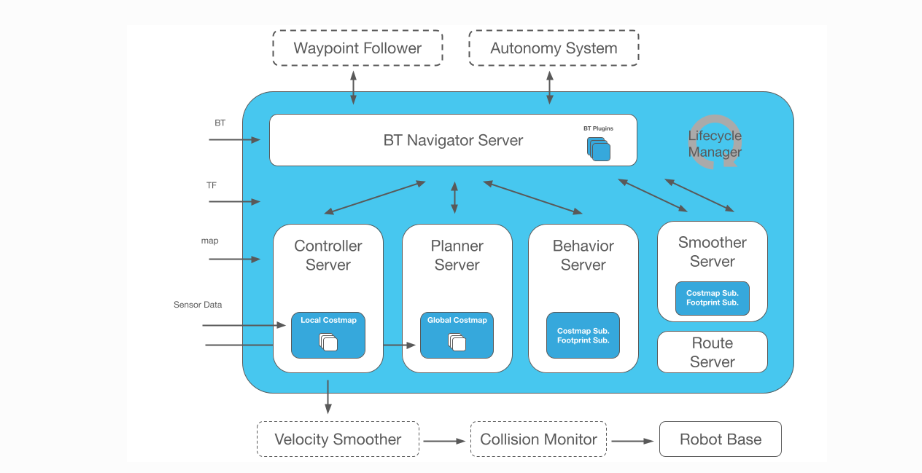
Navigation2 provides the following tools:
- Tools for loading, serving, and storing maps (Map Server)
- Tools for localizing the robot on a map (AMCL)
- Tools for planning paths from point A to point B while avoiding obstacles (Nav2 Planner)
- Tools for controlling the robot while following a path (Nav2 Controller)
- Tools for converting sensor data into a costmap representation of the robot's world (Nav2 Costmap 2D)
- Tools for building complex robot behaviors using behavior trees (Nav2 Behavior Trees and BT Navigator)
- Tools for calculating recovery behaviors in the event of a failure (Nav2 Recoveries)
- A tool for following sequential waypoints (Nav2 Waypoint Follower)
- A tool and watchdog for managing the server lifecycle (Nav2 Lifecycle Manager)
- A plugin for enabling user-defined algorithms and behaviors (Nav2 Core)
Navigation 2 (Nav2) is the native navigation framework in ROS 2. Its purpose is to safely move mobile robots from point A to point B. Nav2 implements behaviors such as dynamic path planning, motor speed calculation, obstacle avoidance, and structure recovery.
Nav2 uses behavior trees (BTs) to call modular servers to complete an action. Actions can include path calculation, control efforts, recovery, or other navigation-related actions. These actions are independent nodes that communicate with the behavior tree (BT) through the action server.
2.2 Related Materials
Navigation2 Documentation: https://navigation.ros.org/index.html
Navigation2 GitHub: https://github.com/ros-planning/navigation2
Navigation2 Paper: https://arxiv.org/pdf/2003.00368.pdf
3. Preparation
3.1 Content Description
This lesson uses the Jetson Orin NX as an example. For Raspberry Pi and Jetson Nano boards, you need to open a terminal and enter the command to enter the Docker container. Once inside the Docker container, enter the commands mentioned in this lesson in the terminal. For instructions on entering the Docker container, refer to the product tutorial [Configuration and Operation Guide]--[Enter the Docker (Jetson Nano and Raspberry Pi 5 users, see here)]. For Orin and NX boards, simply open a terminal and enter the commands mentioned in this lesson.
3.2 Starting the Agent
Note: The Docker agent must be started before testing all examples. If it's already started, you don't need to restart it.
Enter the following command in the vehicle terminal:
xxxxxxxxxxsh start_agent.sh
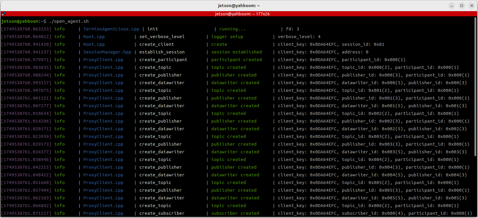
The terminal prints the following message, indicating a successful connection.
4. Running the Example
4.1 Single-Click Navigation
Note:
- For Jetson Nano and Raspberry Pi series controllers, you must first enter the Docker container (see the [Docker Course Section - Entering the Robot's Docker Container] for steps).
- This section requires at least one existing map. Refer to any of the SLAM mapping courses, such as Gmapping-SLAM Mapping, Cartographer Mapping, or Slam-Toolbox Mapping.
To start the underlying sensor on the robot terminal:
xxxxxxxxxxros2 launch M3Pro_navigation base_bringup.launch.pyTo start navigation again:
xxxxxxxxxxros2 launch M3Pro_navigation navigation2.launch.py
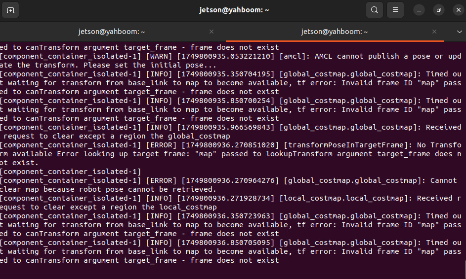
The rviz visualization function can be started on either the vehicle terminal or the virtual machine. Select either method. Do not start both the virtual machine and the vehicle terminal at the same time:
For example, using a virtual machine, open a terminal and start the rviz visualization interface:
xxxxxxxxxxros2 launch slam_view nav_rviz.launch.pyCommand to launch the Rviz visualization interface on the vehicle:
xxxxxxxxxxros2 launch M3Pro_navigation nav_rviz.launch.py
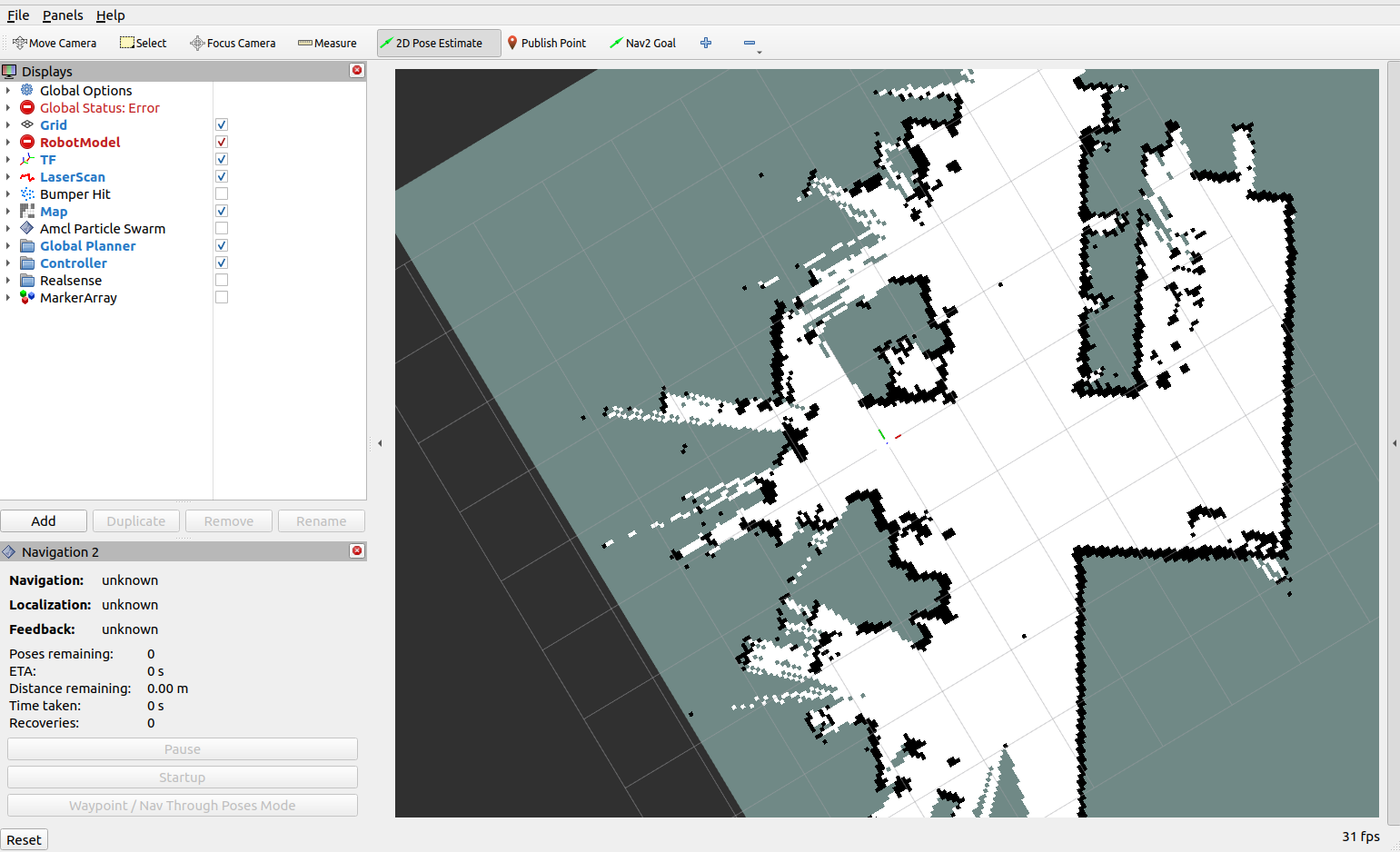
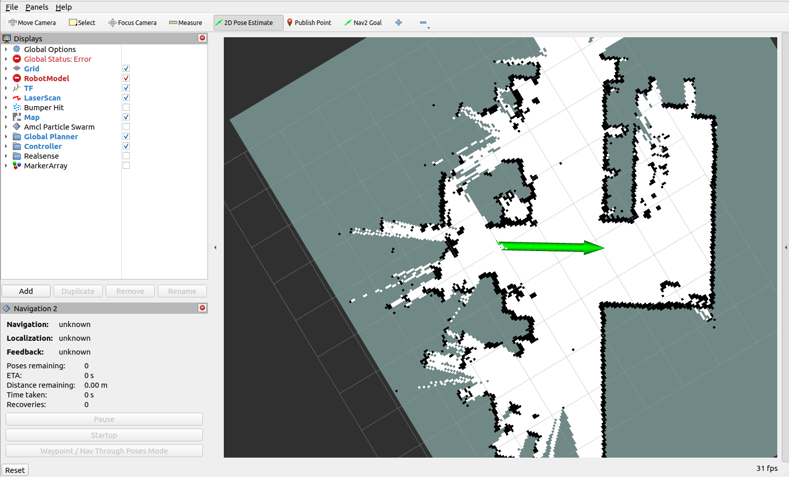
You can now see the map loading. Click [2D Pose Estimate] to set the initial pose for the car. Based on the car's actual position in the environment, click and drag the mouse in Rviz to move the car model to the set position. As shown in the figure below, if the radar scan area roughly overlaps with the actual obstacle, the pose is accurate.
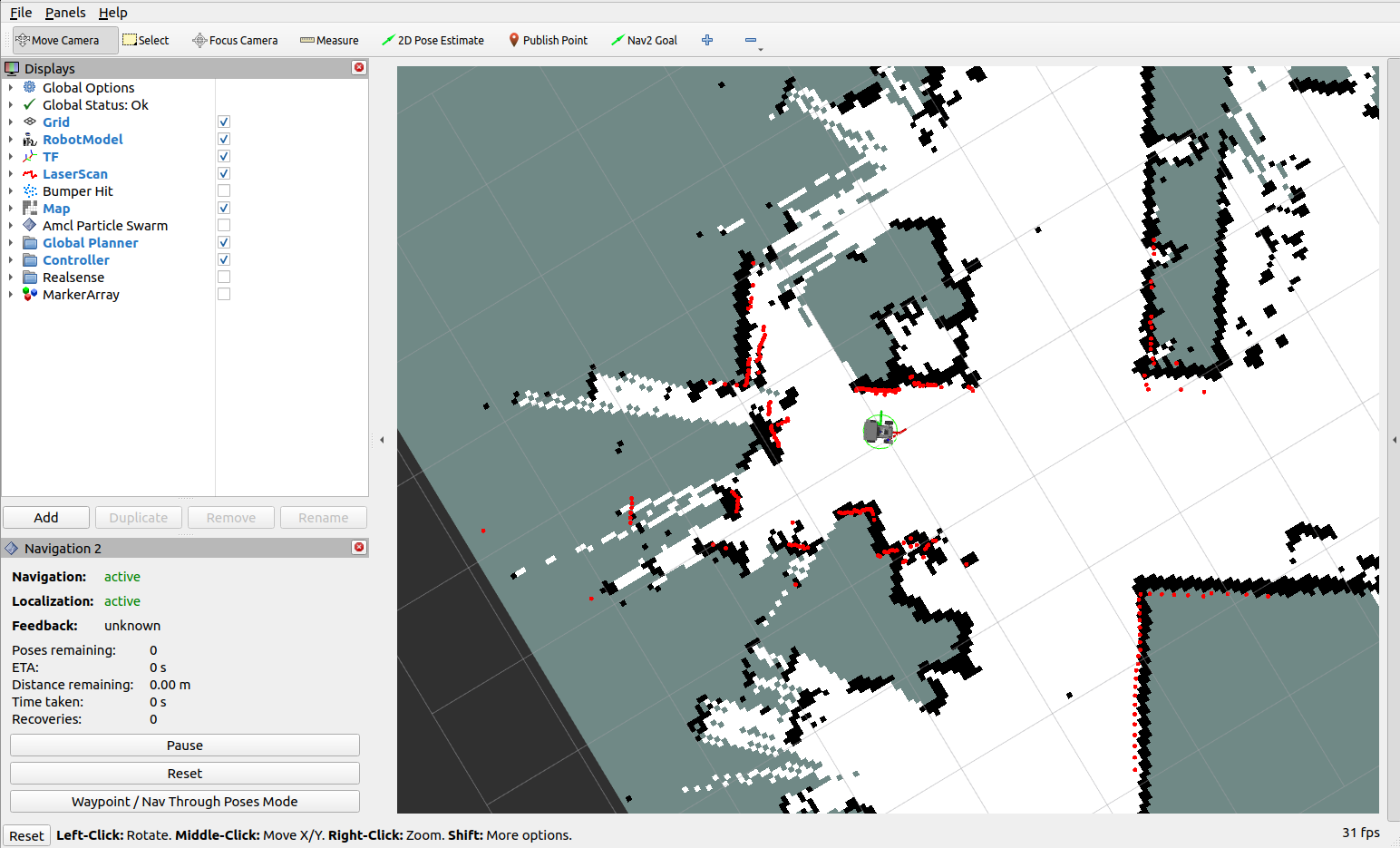
After pose initialization is complete, the robot model and the red LiDAR 2D point cloud will appear in the rviz interface.
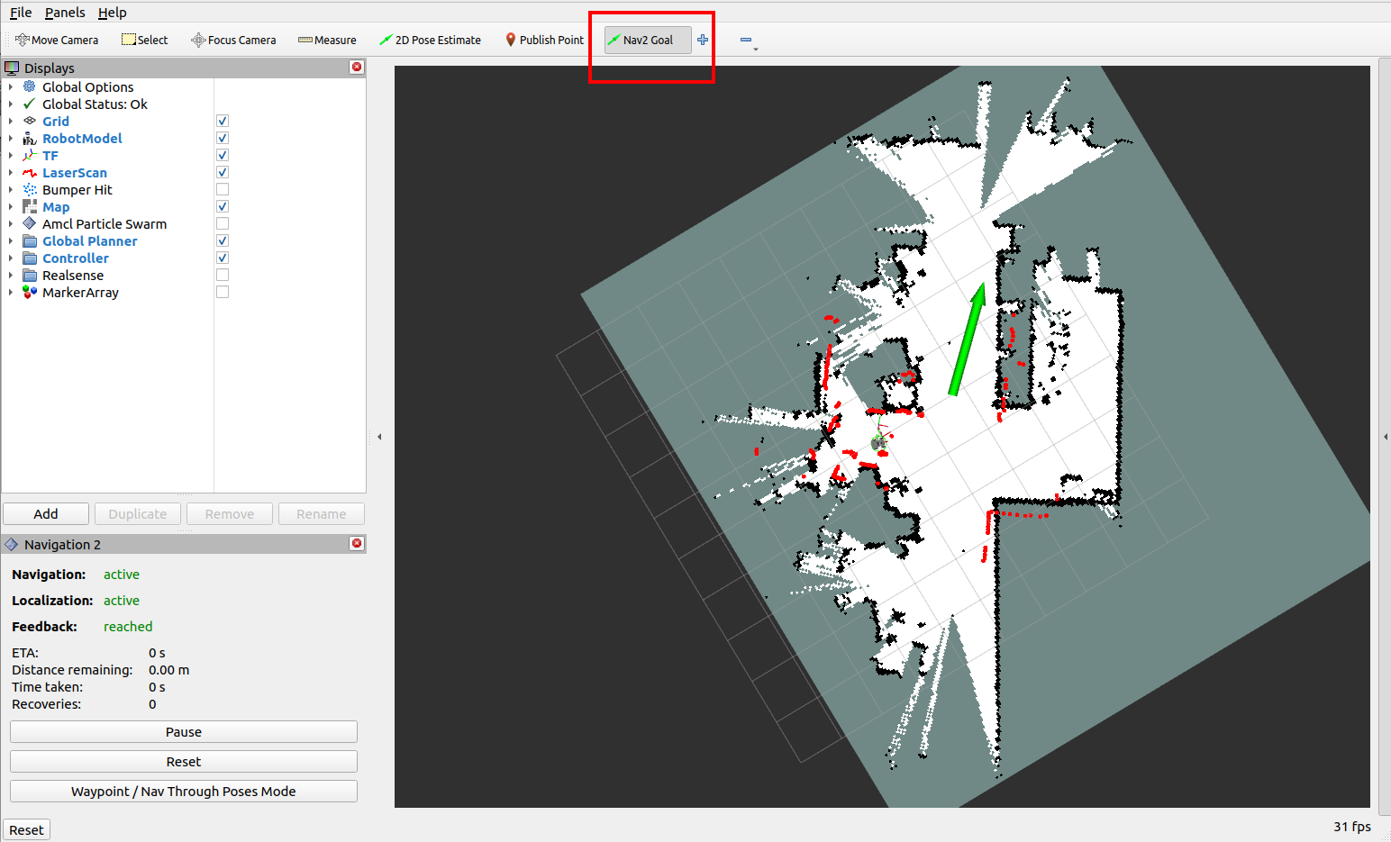
For single-point navigation, click the [2D Goal Pose] tool, then use the mouse to select a target point and orientation in rviz, then release.
The robot plans a path based on its surroundings and moves along it to the target point.
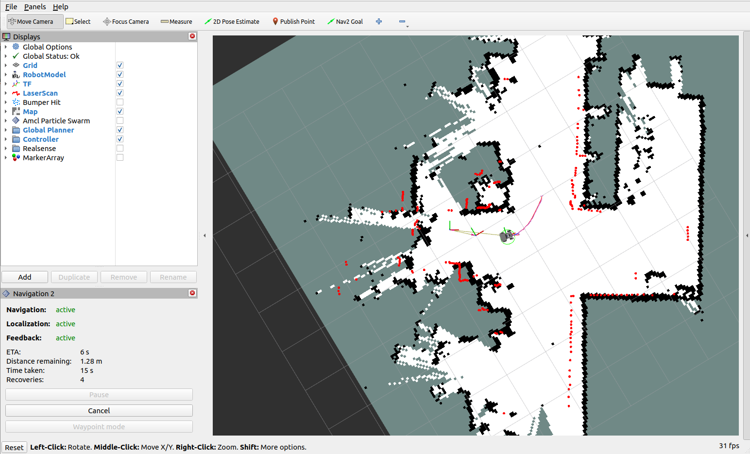
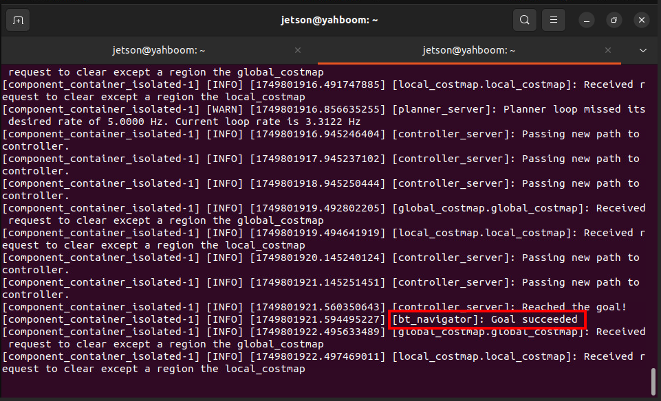
After the robot successfully reaches the target point, the vehicle terminal will display "Goal succeeded," indicating successful navigation.
4.2 Viewing the Costmap
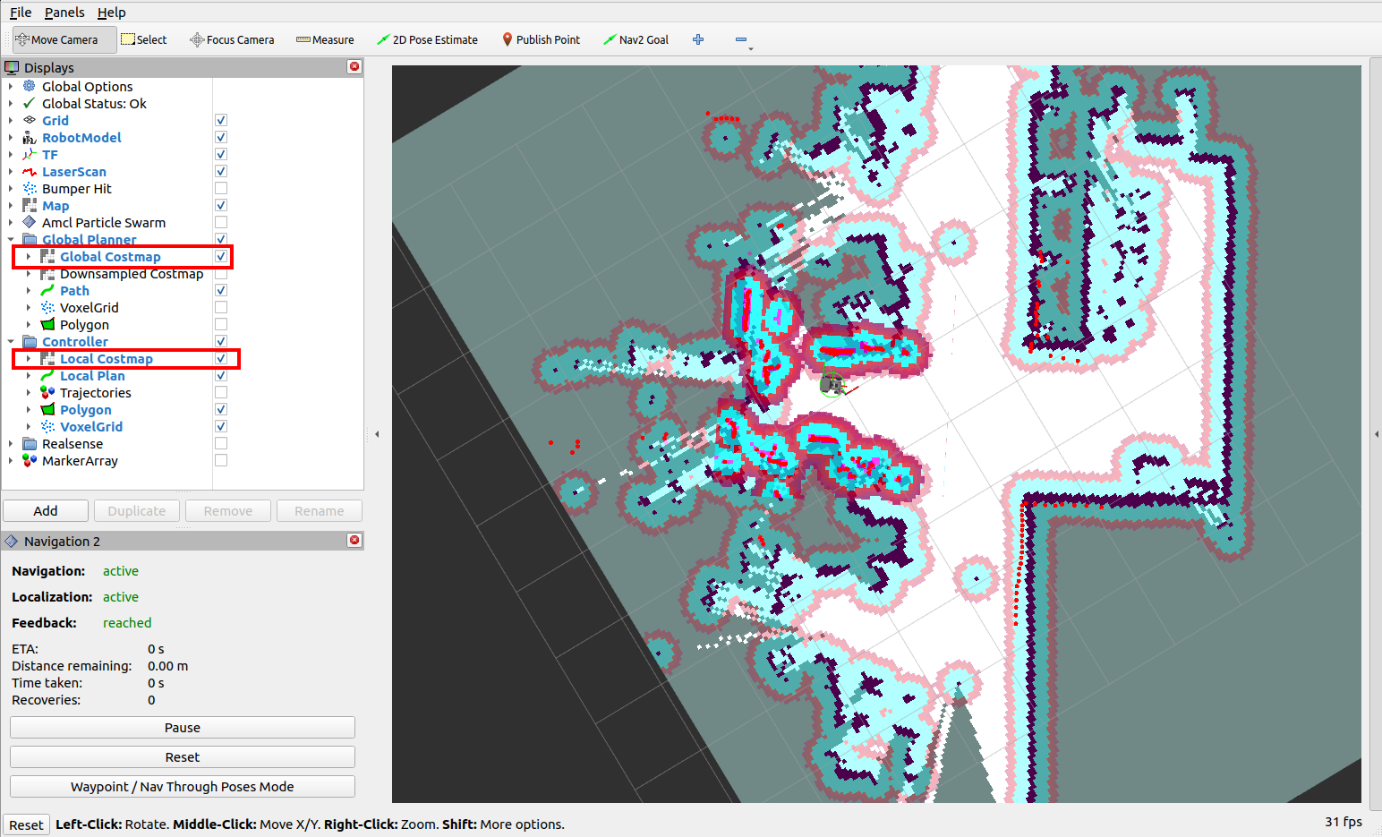
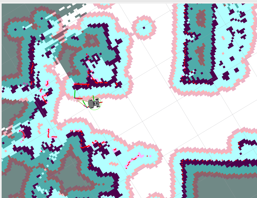
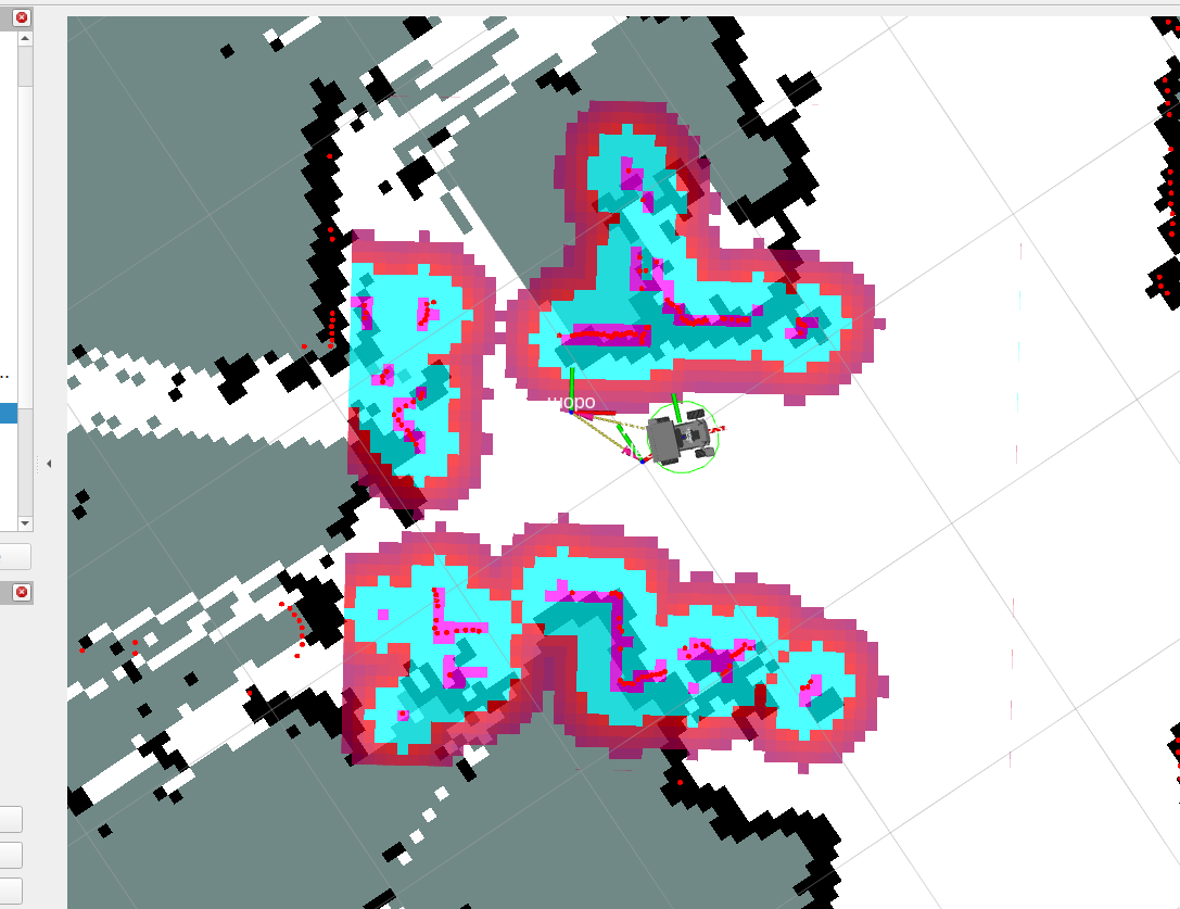
To view the global and local costmaps, locate Global Costmap under the Global Planner group in the left-hand configuration pane and select it to display the global costmap. Similarly, locate Local Costmap under the Controller group and select it. Click the Costmap option to display the costmap (the concept of costmaps will be explained in the theoretical section below).
4.3 Viewing the Node Communication Graph
In the VM terminal, enter:
xxxxxxxxxxros2 run rqt_graph rqt_graphIf the graph does not display initially, select [Nodes/Topics (all)] and click the refresh button in the upper left corner. The original graph is too large; you can view it in the current lesson folder.

4.4 Viewing the TF Tree
In the VM terminal, enter:
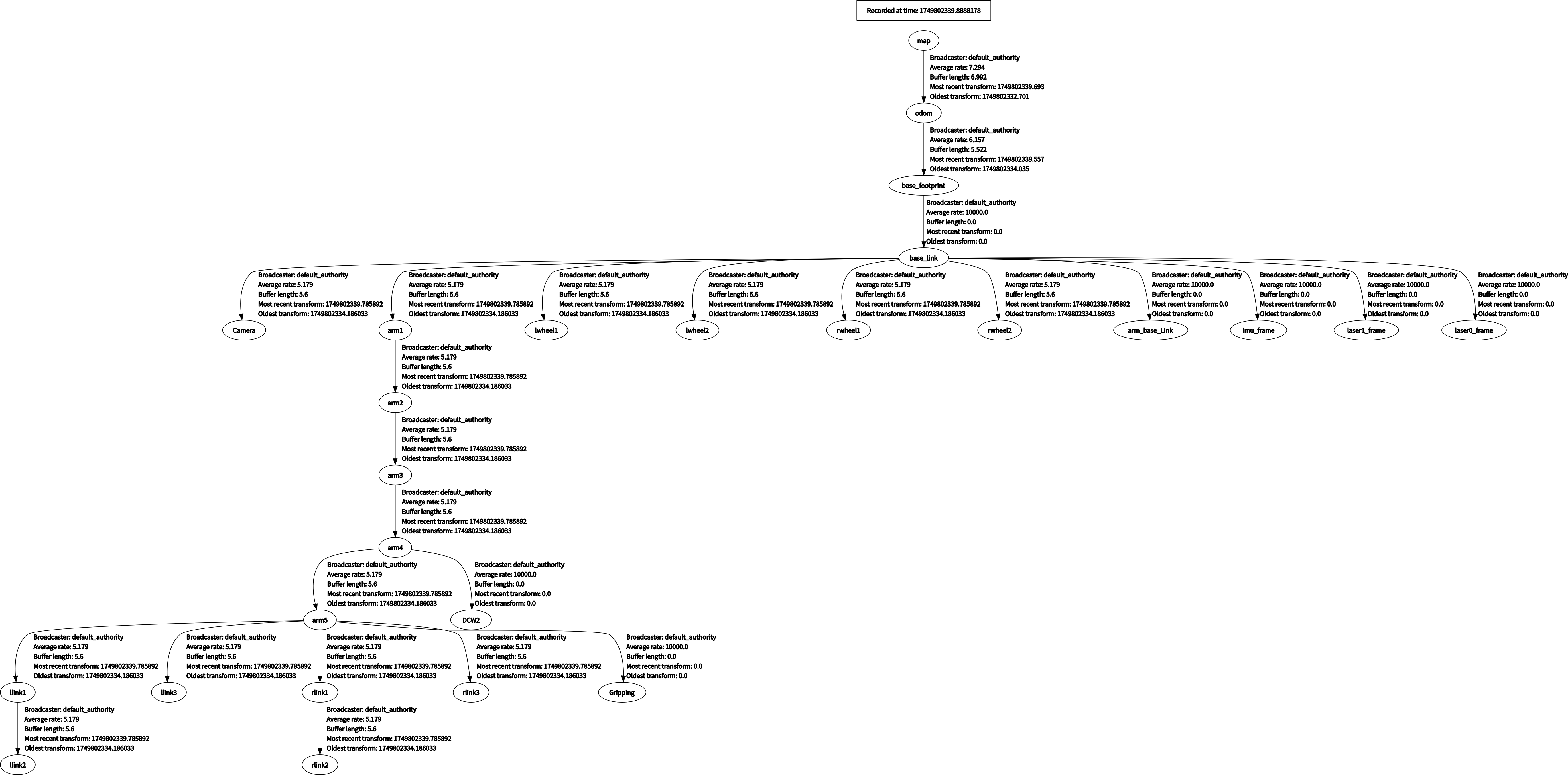
xxxxxxxxxxros2 run rqt_tf_tree rqt_tf_treeIf the page doesn't display initially, click the refresh icon in the upper left corner to refresh the page. The original image is too large; you can view it in the course folder.
5. Navigation Explanation
5.1 Core Steps of the Navigation Process
5.1.1 Phase 1: System Initialization and Map Loading
- Map Acquisition
- Load a pre-built raster map from
map_server - The map contains static obstacle information and serves as the basic environment model for navigation.
Cost Map Initialization
- Global Costmap: Based on the static map, used for global path planning.
- Local Costmap: Integrates the real-time
scantopic of the lidar for dynamic obstacle avoidance.
5.1.2 Phase 2: Sensor Data Processing and Environmental Perception
Sensor Data Access
- LiDAR (/scan), IMU (/imu/data), and odometry (/odom) data are input via ROS topics.
Cost Map Update
- The local cost map updates dynamic obstacle information in real time. Each grid cell calculates occupancy probability and cost based on sensor data (e.g., the closer to the obstacle, the higher the cost).
- Inflation: Expands the edges of obstacles to prevent the robot from getting too close.
5.1.3 Phase 3: Path Planning (Global and Local Planning)
Global Path Planning
- Input: Start point (current robot pose), end point (goal pose), and global cost map.
- The Dijkstra planner algorithm generates an optimal path (a series of discrete coordinate points) from the start point to the end point.
Local Path Planning and Tracking
The local planner, DWBLocalPlanner, generates short-term control commands that the robot can execute based on the global path and the local costmap.
5.1.4 Phase 4: Control Execution and Behavior Decision-Making
Controller Output
- The controller converts the local path into the robot's linear velocity (
linear.x) and angular velocity (angular.z), which are published via the/cmd_veltopic. - Velocity Smoothing: This prevents abrupt changes in robot motion and improves stability.
Behavior Tree Decision Process
The behavior tree defines the priority and state transition logic for navigation tasks. A typical process is as follows:
- Checking if the target is reachable: If global planning fails, trigger a "recovery behavior" (e.g., replanning).
- Performing Local Obstacle Avoidance: When an obstacle is detected in the local costmap, temporarily deviate from the global path.
- Reaching the Target: When the error between the robot's pose and the target pose is less than a threshold, the task is completed.
Recovery Behavior Mechanism
When navigation encounters an anomaly (such as a completely blocked path), a pre-set recovery strategy (such as rotating to search for a new path or backing off to replan) is triggered.
5.2 Key Technical Principles
5.2.1 Costmap
- Probabilistic Grid Representation: Each grid stores an occupancy probability (0-1) and is updated based on sensor data (such as raycast detection by LiDAR).
- Multi-layer Cost Overlay: Static cost (for obstacles in the map) + Dynamic cost (for obstacles detected by real-time sensors) + Inflated cost (for safety distance).
A costmap is a 2D or 3D map created and updated by the robot using sensor information. The following figure provides a brief overview.
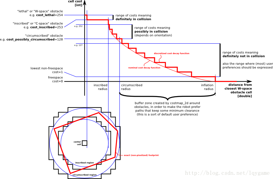
In the figure above, the red area represents obstacles in the costmap, the blue area represents obstacles expanded by the radius of the robot's inscribed circle, and the red polygon represents the footprint (the vertical projection of the robot's outline). To avoid collisions, the footprint should not intersect the red area, and the robot's center should not intersect the blue area. The ROS costmap uses a grid format, with each cell value (cell cost) ranging from 0 to 255. It is divided into three states: occupied (obstacles present), free area (no obstacles), and unknown area.
The specific states and values are shown in the following figure:
The above figure can be divided into five parts, with the red polygon representing the robot's outline:
- Lethal: The robot's center coincides with the center of the grid; in this case, the robot will definitely collide with the obstacle.
- Inscribed: The grid's circumscribed circle is inscribed within the robot's outline; in this case, the robot will definitely collide with the obstacle.
- Possibly circumscribed: The grid's circumscribed circle is inscribed within the robot's outline; in this case, the robot is essentially close to the obstacle, so a collision is not certain.
- Freespace: Space without obstacles.
- Unknown: Space without known locations.
Global Costmap:
Local Costmap:
5.2.2 AMCL Localization Algorithm
AMCL (Adaptive Monte Carlo Localization) is a probabilistic localization system for 2D mobile robots. It implements an adaptive (or KLD sampling) Monte Carlo localization method that uses a particle filter to estimate the robot's position based on a given map.
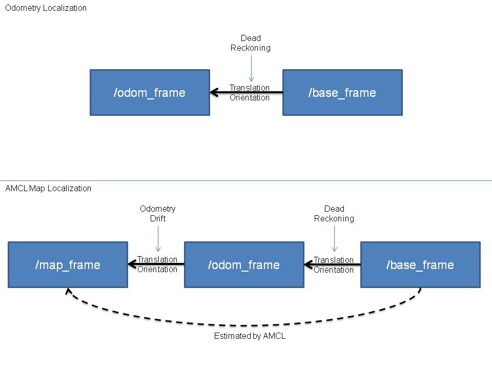
As shown in the figure below, if the odometry is error-free, in a perfect world, we can directly use the odometry information (top half) to infer the robot's (base_frame) position relative to the odometry coordinate system. However, in reality, odometry drift and non-negligible cumulative errors exist. Therefore, AMCL uses the method in the bottom half. This method first uses the odometry information to preliminarily locate the base_frame. Then, using the measurement model, we determine the base_frame's position relative to the map_frame (global map coordinate system), thus determining the robot's position within the map. (Note that although the conversion from base to map is estimated here, the conversion from map to odom is finally published, which can be understood as the drift of the odometry.)
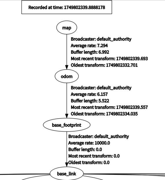
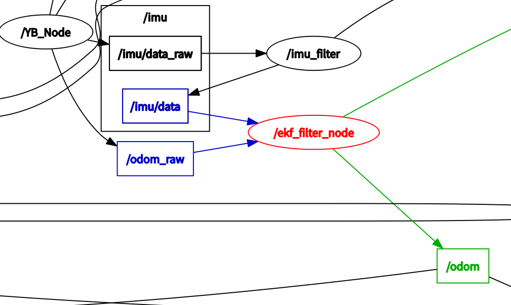
In the TF tree during robot navigation, the coordinate transformation between map (map coordinate system) and odom (odometry coordinate system) is published by the AMCL positioning algorithm, while the coordinate transformation between odom (odometry coordinate system) and besel_footprint (robot chassis center projection coordinate system) is published by the ekf_filter_node node under the robot_localization function package. Its function is to publish the odometry information after the fusion of the IMU sensor and the encoder raw mileage.
In the node communication diagram above, we can see the communication data flow for the ekf_filter_node.
The /YB_Node node is the robot chassis node, publishing /imu/data_raw (raw IMU sensor data) and /odom_raw (raw encoder odometry data).
The imu_filter node subscribes to /imu_data_raw published by the robot chassis. u/data_raw** (raw IMU sensor data). The imu_filter node filters the raw IMU sensor data and publishes it to the /imu/data topic.
The ekf_filter_node node subscribes to the /odom and /imu/data topics, fuses the multi-sensor data, and publishes it to the /odom topic.
5.3 Path Planning
5.3.1 Global Path Planning
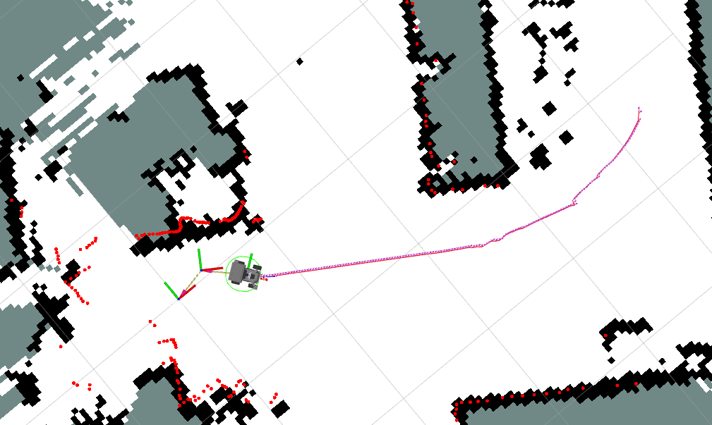
Global path planning calculates an optimal or feasible global path from a start point to a destination within a known environment map, disregarding real-time obstacles. The path from the start point to the destination is calculated with the global optimum as the goal. As shown in the figure below, the path connected by arrows is the global path.
5.3.2 Local Path Planning
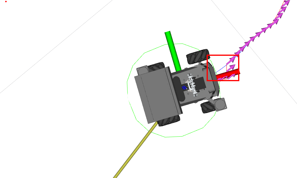
Local path planning dynamically adjusts the robot's path based on real-time LiDAR sensor data during movement to avoid obstacles (obstacles are displayed in the costmap). As shown in the figure below, the blue path is the local path.
5.4 Navigation Parameter Configuration
Configuration file path:
For Jetson Nano and Raspberry Pi, you must first enter Docker:
xxxxxxxxxx/root/M3Pro_ws/src/M3Pro_navigation/param/yahboom_M3Pro.yaml
For Jetson Orin Nano and NX:
xxxxxxxxxx/home/jetson/M3Pro_ws/src/M3Pro_navigation/param/yahboom_M3Pro.yaml
The default configuration parameters for the navigation function are as follows:
x
# AMCL (Adaptive Monte Carlo Localization) configurationamcl ros__parameters # Whether to use simulation time, False means use real time use_sim_time False # Control the noise parameters of the odometer model when the robot rotates alpha1 0.2 # Control the noise parameters of the odometry model when the robot rotates and translates alpha2 0.2 # Control the noise parameters of the odometer model when the robot translates alpha3 0.2 # Control the noise parameters of the odometer model when the robot is rotated due to translation alpha4 0.2 # Control the noise parameters of the odometry model when the robot rotates (another aspect) alpha5 0.2 # The name of the robot's base coordinate system base_frame_id "base_footprint" # The distance threshold for beam skipping, used for laser scanning data processing beam_skip_distance 0.5 # The error threshold for beam skipping, used to decide whether to skip certain beams beam_skip_error_threshold 0.9 # The beam skipping threshold is used to decide whether to skip certain beams beam_skip_threshold 0.3 # Whether to enable beam skipping function do_beamskip false # Global coordinate system name global_frame_id "map" # Attenuation coefficient of short laser reflection lambda_short 0.1 # Maximum likelihood distance for laser scanning laser_likelihood_max_dist 2.0 # Maximum range of laser scanning laser_max_range 100.0 # Minimum range of laser scanning laser_min_range -1.0 # Laser model type laser_model_type "likelihood_field" # Maximum number of laser beams to use per update max_beams 60 # Maximum number of particles allowed in the particle filter max_particles 2000 # Minimum number of particles allowed in the particle filter min_particles 500 # Odometer coordinate system name odom_frame_id "odom" # Error threshold of particle filter pf_err 0.05 # Confidence threshold for particle filter pf_z 0.99 # Fast recovery factor, used for the recovery mechanism of the particle filter recovery_alpha_fast 0.0 # Slow recovery factor, used for the recovery mechanism of the particle filter recovery_alpha_slow 0.0 # Resampling interval resample_interval 1 # The robot's motion model type robot_model_type "nav2_amcl::DifferentialMotionModel" # Save the rate of the robot's posture save_pose_rate 0.5 # Standard deviation of laser hits sigma_hit 0.2 # Whether to broadcast TF transformation tf_broadcast true # TF Transform Release Rate tf_publish_rate 10.0 # Transformation tolerance time transform_tolerance 0.2 # Minimum threshold for angle update update_min_a 0.2 # Minimum threshold for distance update update_min_d 0.25 # Weight of laser hit z_hit 0.5 # Weight of the laser's maximum range z_max 0.05 # Weights of random laser measurements z_rand 0.5 # Weight of short laser reflections z_short 0.05 #Topic name for laser scanning data scan_topic scan# AMCL map client configurationamcl_map_client ros__parameters # Whether to use simulation time, False means use real time use_sim_time False# AMCL RCLCPP node configurationamcl_rclcpp_node ros__parameters # Whether to use simulation time, False means use real time use_sim_time False# BT Navigator Configurationbt_navigator ros__parameters # Whether to use simulation time, False means use real time use_sim_time False # Global coordinate system name global_frame map # The name of the robot's base coordinate system robot_base_frame base_link # Topic name for odometer data odom_topic /odom # Default behavior tree XML file name default_bt_xml_filename "navigate_w_replanning_and_recovery.xml" # Behavior Tree Loop bt_loop_duration 10 #Default server timeout default_server_timeout 20 # Whether to enable Groot monitoring enable_groot_monitoring True # Groot's ZMQ publisher port groot_zmq_publisher_port 1666 # Groot's ZMQ server port groot_zmq_server_port 1667 # List of behavior tree plugin library names plugin_lib_names nav2_compute_path_to_pose_action_bt_nodenav2_compute_path_through_poses_action_bt_nodenav2_follow_path_action_bt_nodenav2_back_up_action_bt_nodenav2_spin_action_bt_nodenav2_wait_action_bt_nodenav2_clear_costmap_service_bt_nodenav2_is_stuck_condition_bt_nodenav2_goal_reached_condition_bt_nodenav2_goal_updated_condition_bt_nodenav2_initial_pose_received_condition_bt_nodenav2_reinitialize_global_localization_service_bt_nodenav2_rate_controller_bt_nodenav2_distance_controller_bt_nodenav2_speed_controller_bt_nodenav2_truncate_path_action_bt_nodenav2_goal_updater_node_bt_nodenav2_recovery_node_bt_nodenav2_pipeline_sequence_bt_nodenav2_round_robin_node_bt_nodenav2_transform_available_condition_bt_nodenav2_time_expired_condition_bt_nodenav2_distance_traveled_condition_bt_nodenav2_single_trigger_bt_nodenav2_is_battery_low_condition_bt_nodenav2_navigate_through_poses_action_bt_nodenav2_navigate_to_pose_action_bt_nodenav2_remove_passed_goals_action_bt_nodenav2_planner_selector_bt_nodenav2_controller_selector_bt_nodenav2_goal_checker_selector_bt_node# BT Navigator RCLCPP node configurationbt_navigator_rclcpp_node ros__parameters # Whether to use simulation time, False means use real time use_sim_time False# Controller Server Configurationcontroller_server ros__parameters # Whether to use simulation time, False means use real time use_sim_time False # The controller's operating frequency controller_frequency 5.0 # Minimum speed threshold in the X direction min_x_velocity_threshold 0.001 # Minimum speed threshold in the Y direction min_y_velocity_threshold 0.5 # Minimum speed threshold for rotation direction min_theta_velocity_threshold 0.001 # Maximum failure tolerance allowed failure_tolerance 0.3 # Progress checker plugin name progress_checker_plugin "progress_checker" # List of target checker plugin names goal_checker_plugins "general_goal_checker" # List of controller plugin names controller_plugins "FollowPath" # Progress Checker Parameters progress_checker # Progress Checker Plugin Type plugin "nav2_controller::SimpleProgressChecker" # The minimum radius the robot must move required_movement_radius 0.5 # Maximum allowed movement time movement_time_allowance 10.0 general_goal_checker # Is this a stateful target checker? stateful True # Target Inspector Plugin Type plugin "nav2_controller::SimpleGoalChecker" # Target tolerance in X and Y directions xy_goal_tolerance 0.15 # Target tolerance for rotation direction yaw_goal_tolerance 0.15 # DWB local planner parameters FollowPath # Local planner plugin type plugin "dwb_core::DWBLocalPlanner" # Whether to debug trajectory details debug_trajectory_details True # Minimum speed in the X direction min_vel_x 0.0 # Minimum speed in the Y direction min_vel_y 0.0 # Maximum speed in the X direction max_vel_x 0.35 # Maximum speed in the Y direction max_vel_y 0.0 # Maximum speed in the direction of rotation max_vel_theta 1.0 # Minimum speed in the XY plane min_speed_xy 0.0 # Maximum speed in the XY plane max_speed_xy 0.22 # Minimum speed in the direction of rotation min_speed_theta 0.0 # Acceleration limit in X direction acc_lim_x 2.5 # Acceleration limit in the Y direction acc_lim_y 0.0 # Acceleration limit in the rotation direction acc_lim_theta 3.2 # Deceleration limit in X direction decel_lim_x -2.5 # Deceleration limit in Y direction decel_lim_y 0.0 # Deceleration limit in the rotation direction decel_lim_theta -3.2 # Number of velocity samples in the X direction vx_samples 20 # Number of velocity samples in the Y direction vy_samples 0 # Number of speed samples in the rotation direction vtheta_samples 40 # Simulation time sim_time 1.5 Linear resolution linear_granularity 0.05 # Angular resolution angular_granularity 0.025 # Transformation tolerance time transform_tolerance 0.2 # Target tolerance in X and Y directions xy_goal_tolerance 0.05 # Speed threshold for panning to stop trans_stopped_velocity 0.25 # Whether to short-circuit trajectory evaluation short_circuit_trajectory_evaluation True # Is it a stateful planner? stateful True # Evaluator list critics "RotateToGoal" "Oscillation" "BaseObstacle" "GoalAlign" "PathAlign" "PathDist" "GoalDist" # Weight of the basic obstacle evaluator BaseObstacle.scale 0.02 # Weights of the path alignment evaluator PathAlign.scale 32.0 # Forward point distance of path alignment evaluator PathAlign.forward_point_distance 0.1 # Weights of the target alignment evaluator GoalAlign.scale 24.0 # Forward point distance of target alignment evaluator GoalAlign.forward_point_distance 0.1 # Weight of the path distance evaluator PathDist.scale 32.0 # Weight of target distance evaluator GoalDist.scale 24.0 # Rotate to the target evaluator weights RotateToGoal.scale 32.0 #Deceleration factor for rotating to target evaluator RotateToGoal.slowing_factor 5.0 # Rotate to the look-ahead time of the target evaluator RotateToGoal.lookahead_time -1.0 # Controller server RCLCPP node configurationcontroller_server_rclcpp_node ros__parameters # Whether to use simulation time, False means use real time use_sim_time False # Local costmap configurationlocal_costmap local_costmap ros__parameters # Costmap update frequency update_frequency 5.0 # How often the costmap is published publish_frequency 2.0 # Global coordinate system name global_frame odom # The name of the robot's base coordinate system robot_base_frame base_link # Whether to use simulation time, False means use real time use_sim_time False # Whether to use rolling window rolling_window true # The width of the costmap width 3 # The height of the costmap height 3 # Costmap resolution resolution 0.05 # The radius of the robot robot_radius 0.15 # List of costmap plugins plugins "obstacle_layer" "voxel_layer" "inflation_layer" inflation_layer # Expansion layer plugin type plugin "nav2_costmap_2d::InflationLayer" # Expansion radius inflation_radius 0.3 # Cost scaling factor cost_scaling_factor 3.0 obstacle_layer # Obstacle layer plugin type plugin "nav2_costmap_2d::ObstacleLayer" # Whether to enable the obstacle layer enabled True # Observation source name observation_sources scan scan #Topic name for laser scanning data topic /scan # Maximum obstacle height max_obstacle_height 2.0 # Whether to clear obstacles clearing True # Whether to mark obstacles marking True # Data Types data_type "LaserScan" voxel_layer # Voxel layer plugin type plugin "nav2_costmap_2d::VoxelLayer" # Whether to enable voxel layer enabled True # Whether to publish voxel map publish_voxel_map True # Z-origin origin_z 0.0 # Z resolution z_resolution 0.05 # Number of voxels in the Z direction z_voxels 16 # Maximum obstacle height max_obstacle_height 2.0 # Marking threshold mark_threshold 0 # Observation source name observation_sources scan scan #Topic name for laser scanning data topic /scan # Maximum obstacle height max_obstacle_height 2.0 # Whether to clear obstacles clearing True # Whether to mark obstacles marking True # Data Types data_type "LaserScan" # Maximum range of ray tracing raytrace_max_range 3.0 # Minimum range for ray tracing raytrace_min_range 0.0 # Maximum detection range of obstacles obstacle_max_range 2.5 # Minimum obstacle detection range obstacle_min_range 0.0 static_layer # Whether to subscribe to transient local map map_subscribe_transient_local True # Whether to always send the full costmap always_send_full_costmap True local_costmap_client ros__parameters # Whether to use simulation time, False means use real time use_sim_time False local_costmap_rclcpp_node ros__parameters # Whether to use simulation time, False means use real time use_sim_time False# Global costmap configurationglobal_costmap global_costmap ros__parameters # Costmap update frequency update_frequency 1.0 # How often the costmap is published publish_frequency 1.0 # Global coordinate system name global_frame map # The name of the robot's base coordinate system robot_base_frame base_link # Whether to use simulation time, True means to use simulation time use_sim_time True # The radius of the robot robot_radius 0.2 # Costmap resolution resolution 0.05 # Whether to track unknown space track_unknown_space false # List of costmap plugins plugins "static_layer" "obstacle_layer" "voxel_layer" "inflation_layer" obstacle_layer # Obstacle layer plugin type plugin "nav2_costmap_2d::ObstacleLayer" # Whether to enable the obstacle layer enabled True # Observation source name observation_sources scan scan #Topic name for laser scanning data topic /scan # Maximum obstacle height max_obstacle_height 2.0 # Whether to clear obstacles clearing True # Whether to mark obstacles marking True # Data Types data_type "LaserScan" # Maximum range of ray tracing raytrace_max_range 3.0 # Minimum range for ray tracing raytrace_min_range 0.0 # Maximum detection range of obstacles obstacle_max_range 2.5 # Minimum obstacle detection range obstacle_min_range 0.0 voxel_layer # Voxel layer plugin type plugin "nav2_costmap_2d::VoxelLayer" # Whether to enable voxel layer enabled True # Whether to publish voxel map publish_voxel_map True # Z-origin origin_z 0.0 # Z resolution z_resolution 0.05 # Number of voxels in the Z direction z_voxels 16 # Maximum obstacle height max_obstacle_height 2.0 # Marking threshold mark_threshold 0 # Observation source name observation_sources scan scan #Topic name for laser scanning data topic /scan # Maximum obstacle height max_obstacle_height 2.0 # Whether to clear obstacles clearing True # Whether to mark obstacles marking True # Data Types data_type "LaserScan" # Maximum range of ray tracing raytrace_max_range 3.0 # Minimum range for ray tracing raytrace_min_range 0.0 # Maximum detection range of obstacles obstacle_max_range 2.5 # Minimum obstacle detection range obstacle_min_range 0.0 static_layer # Static layer plugin type plugin "nav2_costmap_2d::StaticLayer" # Whether to subscribe to transient local map map_subscribe_transient_local True inflation_layer # Expansion layer plugin type plugin "nav2_costmap_2d::InflationLayer" # Cost scaling factor cost_scaling_factor 3.0 # Expansion radius inflation_radius 0.3 # Whether to always send the full costmap always_send_full_costmap True global_costmap_client ros__parameters # Whether to use simulation time, False means use real time use_sim_time False global_costmap_rclcpp_node ros__parameters # Whether to use simulation time, False means use real time use_sim_time False# Map server configurationmap_server ros__parameters # Whether to use simulation time, False means use real time use_sim_time False # Name of the map YAML file yaml_filename "map.yaml"# Map saver configurationmap_saver ros__parameters # Whether to use simulation time, False means use real time use_sim_time False # Timeout for saving the map save_map_timeout 5.0 # Default idle threshold free_thresh_default 0.25 #Default occupancy threshold occupied_thresh_default 0.65 # Whether to subscribe to transient local map map_subscribe_transient_local True•# Planner server configurationplanner_server ros__parameters # Desired planner frequency expected_planner_frequency 5.0 # Whether to use simulation time, False means use real time use_sim_time False # List of planner plugin names planner_plugins "GridBased" GridBased # Grid-based planner plugin types plugin "nav2_navfn_planner/NavfnPlanner" # Planning tolerance tolerance 0.5 # Whether to use the A* algorithm use_astar false # Whether to allow unknown space allow_unknown true# Planner server RCLCPP node configurationplanner_server_rclcpp_node ros__parameters # Whether to use simulation time, False means use real time use_sim_time False# Restore server configurationrecoveries_server ros__parameters # The topic name of the costmap costmap_topic local_costmap/costmap_raw # Topic name of the robot footprint footprint_topic local_costmap/published_footprint # Loop frequency cycle_frequency 5.0 # Restore plugin name list recovery_plugins "spin" "backup" "wait" spin # Rotation recovery plugin type plugin "nav2_recoveries/Spin" backup # Back restore plugin type plugin "nav2_recoveries/BackUp" wait # Waiting to restore plugin type plugin "nav2_recoveries/Wait" # Global coordinate system name global_frame odom # The name of the robot's base coordinate system robot_base_frame base_link # Transformation timeout transform_timeout 0.1 # Whether to use simulation time, False means use real time use_sim_time False # Look-ahead simulation time simulate_ahead_time 2.0 # Maximum rotation speed max_rotational_vel 1.0 # Minimum rotation speed min_rotational_vel 0.4 # Rotational acceleration limit rotational_acc_lim 3.2# Robot status publisher configurationrobot_state_publisher ros__parameters # Whether to use simulation time, False means use real time use_sim_time False# Waypoint follower configurationwaypoint_follower ros__parameters # Loop rate loop_rate 2000 # Whether to stop on failure stop_on_failure false #Waypoint task executor plugin name waypoint_task_executor_plugin "wait_at_waypoint" wait_at_waypoint #Waypoint wait plugin type plugin "nav2_waypoint_follower::WaitAtWaypoint" # Whether to enable the plugin enabled True #Waypoint pause duration waypoint_pause_duration 200
The above are the configurable parameters of Navigation2. If the user needs to modify the configuration parameters, after the modification is completed, the M3Pro_navigation function package needs to be recompiled in the M3Pro_ws workspace to take effect:
xxxxxxxxxxcolcon build --packages-select M3Pro_navigation