Welcome to Muto RS Robot repository
7)Tracking
7.Tracking
1. Program function description
After the program is started, adjust the pitch angle of the camera and move the camera downward so that the camera can see the line. Then click on the image window and press the r key to enter the color selection mode; then frame the line area in the picture. Select the color of the required line tracing, and the processed image will be automatically loaded after releasing the mouse; finally, press the space bar to turn on the line tracing function. When Muto is running, it will stop and the buzzer will sound when encountering obstacles; after turning on the handle control program, the R2 key on the handle can pause the Muto movement.
2. Program code reference path
After entering the docker container, the location of the source code of this function is:
/root/yahboomcar_ros2_ws/yahboomcar_ws/src/yahboomcar_linefollow/yahboomcar_linefollow
3. Configuration before use
Note: Since the Muto series robots are equipped with multiple radar devices, the factory system has been configured with routines for multiple devices. However, since the product cannot be automatically recognized, the radar model needs to be manually set.
After entering the container: Make the following modifications according to the radar type:
xxxxxxxxxxroot@ubuntu:/# cdroot@ubuntu:~# vim .bashrc
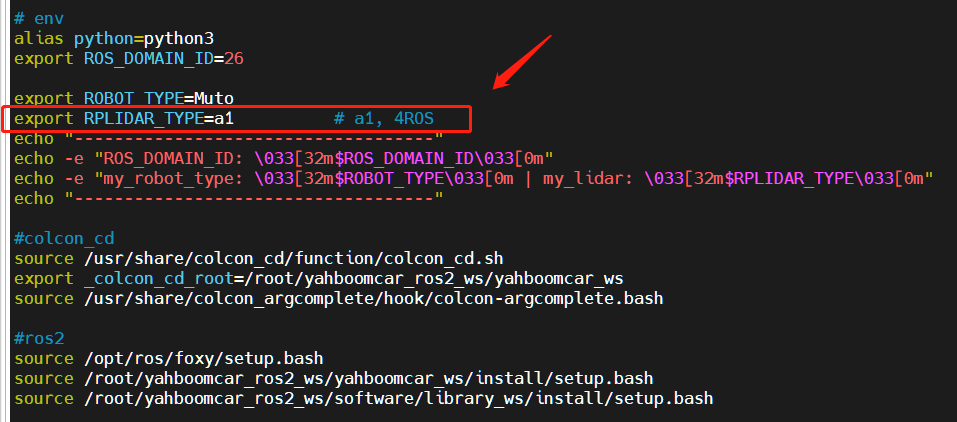
After the modification is completed, save and exit vim, and then execute:
xxxxxxxxxxroot@jetson-desktop:~# source .bashrc------------------------------------ROS_DOMAIN_ID: 26my_robot_type: Muto | my_lidar: a1------------------------------------root@jetson-desktop:~#
You can see the current modified lidar type.
4. Program startup
4.1. Start command
After entering the docker container, enter in the terminal
xxxxxxxxxxros2 launch yahboomcar_linefollow follow_line_launch.pyTake patrolling the blue line as an example,
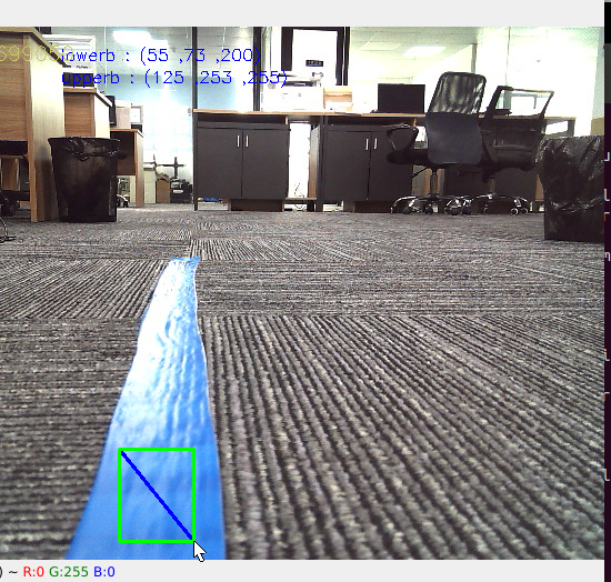
After pressing the r key, select the blue line area as shown above, and release the mouse after selection.
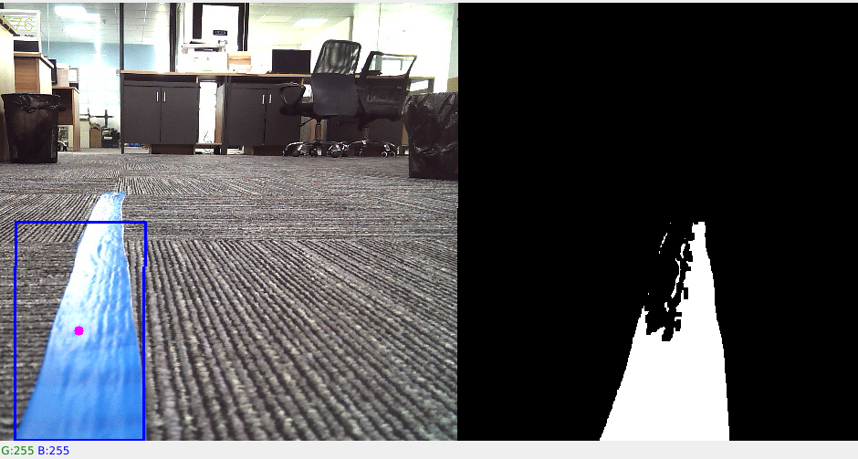
As shown in the picture above, what is shown on the right is the processed image, which will show the blue line part. Then press the space bar to start calculating the speed, and Muto will follow the line and drive automatically.
4.2. Dynamic parameter adjustment
Relevant parameters can be adjusted through the dynamic parameterizer and docker terminal input.
xxxxxxxxxxros2 run rqt_reconfigure rqt_reconfigure
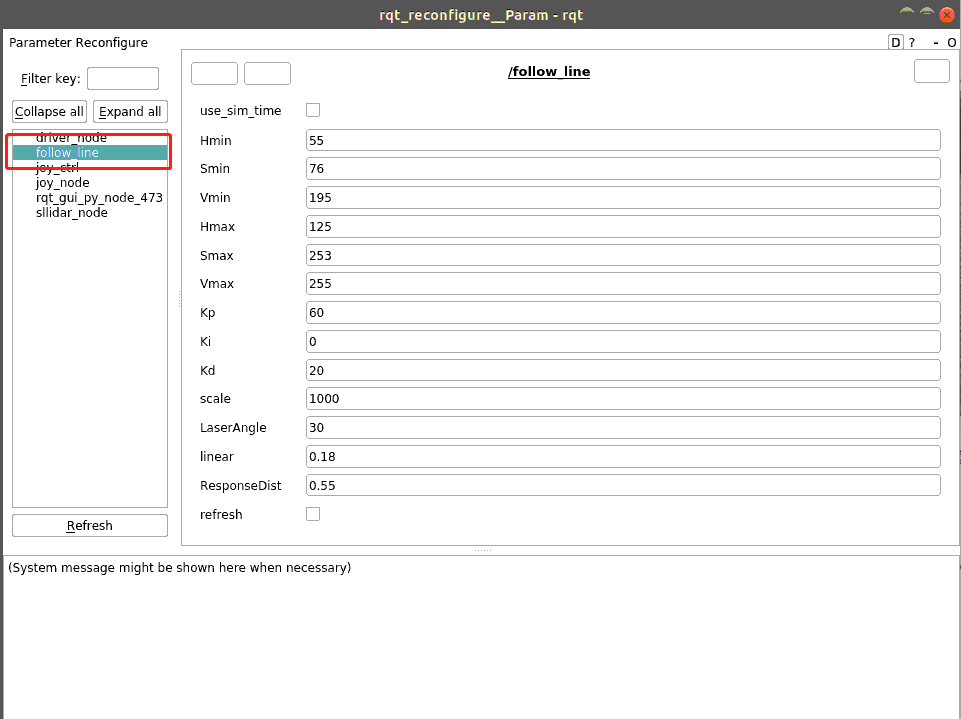
The adjustable parameters include:
| Parameter | Description |
|---|---|
| Kp | P value of PID |
| Ki | I value of PID |
| Kd | D value of PID |
| scale | PID adjustment proportion coefficient |
| LaserAngle | Angle of lidar detection |
| linear | Linear speed size |
| ResponseDist | Obstacle avoidance detection distance |
| refresh | Refresh parameters button |
5. Core code
Let’s first sort out the implementation principle of lower patrol line, through
- Calculate the offset between the center coordinates of the patrol line and the center of the image,
- Calculate the value of angular velocity based on the coordinate offset,
- Release speed driven Muto.
Calculate the center coordinates,
xxxxxxxxxx#Calculate hsv valuergb_img, self.hsv_range = self.color.Roi_hsv(rgb_img, self.Roi_init)#Calculate self.circle and calculate the X coordinate and radius value. A radius value of 0 indicates that no line is detected and parking information is released.rgb_img, binary, self.circle = self.color.line_follow(rgb_img, self.hsv_range)Calculate the value of angular velocity,
xxxxxxxxxx#320 is the value of the X coordinate of the center point. Through the deviation of the X value of the obtained image from 320, we can calculate "how far away from the center I am now", and then calculate the value of the angular velocity[z_Pid, _] = self.PID_controller.update([(point_x - 320)*1.0/16, 0])