Welcome to Muto RS Robot repository
9)About ROS2 Navigation
9.About ROS2 Navigation
9.About ROS2 Navigation1. Introduction2. Navigation2 details2.1. amcl2.2.costmaps and layers2.3.planner_server2.4.controller_server2.5.recoveries_server2.6.waypoint following2.7.bt_navigator2.8. Complete parameter configuration source code
Navigation2 document:https://navigation.ros.org/index.html
Navigation2 github:https://github.com/ros-planning/navigation2
Navigation2 corresponding paper:https://arxiv.org/pdf/2003.00368.pdf
teb_local_planner:https://github.com/rst-tu-dortmund/teb_local_planner/tree/foxy-devel
Navigation2 provided plugins:https://navigation.ros.org/plugins/index.html#plugins
1. Introduction
ROS2 navigation uses Navigation2, Navigation2 overall architecture diagram
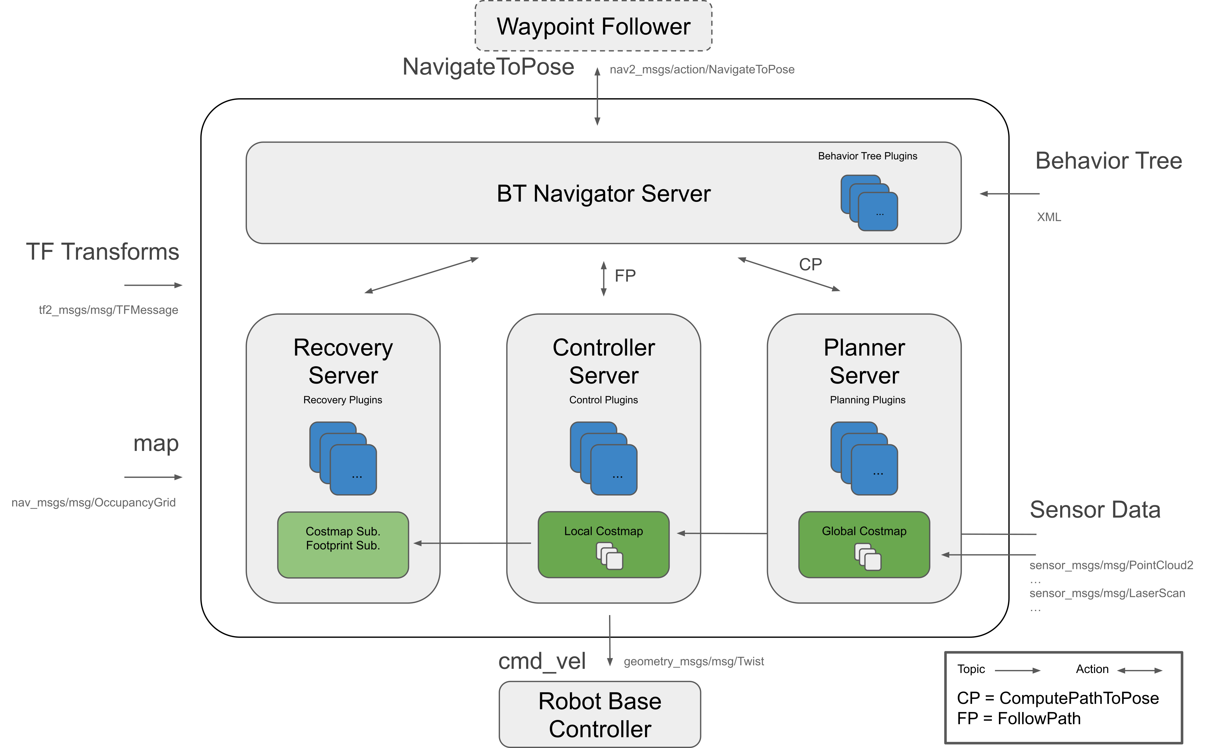
Navigation2 has the following tools:
●Tools for loading, serving and storing maps (Map Server)
● Tools for locating robots on a map (AMCL)
● Path planning tool (Nav2 Planner) to avoid obstacles and move from point A to point B
● Tool for controlling the robot while following the path (Nav2 Controller)
● Tools for converting sensor data into cost map representations in the robotic world (Nav2 Costmap 2D)
● Tools for building complex robot behaviors using behavior trees (Nav2 Behavior Tree and BT Navigator)
● Tools for calculating recovery behavior in the event of failure (Nav2 Recoveries)
● Tool for following sequential waypoints (Nav2 Waypoint Follower)
● Tools and watchdogs for managing server lifecycle (Nav2 Lifecycle Manager)
● Plug-ins that enable user-defined algorithms and behaviors (Nav2 Core)
Navigation 2 (Nav 2) is the navigation framework that comes with ROS 2. Its purpose is to enable the mobile robot to move from point A to point B in a safe way. Therefore, Nav 2 can complete behaviors such as dynamic path planning, calculating motor speed, avoiding obstacles, and restoring structures.
Nav 2 uses behavior trees (BT, Behavior Trees) to call the modular server to complete an action. Actions can be path calculations, control efforts, recovery, or other navigation-related actions. These actions are independent nodes that communicate with the Behavior Tree (BT) through the action server.
2. Navigation2 details
- Comparison of navigation frameworks in ROS 1 and ROS 2
In Nav 2, move_base is split into multiple components. Unlike a single state machine (ROS1), Nav 2 leverages action servers and ROS 2's low-latency, reliable communication to separate minds. The behavior tree is used to orchestrate and organize these tasks, which allows Nav 2 to have highly configurable navigation behavior through the behavior tree xml file without the need to arrange tasks through programming.
nav2_bt_navigator replaces move_base at the top level and uses an Action interface to complete the navigation task of a tree-based action model. Implement more complex state machines through BT and add recovery behavior as additional Action Servers. These behavior trees are configurable xml.
Path planning (planning), recovery (recovery) and controller (controller) servers are also action servers, and BT Navigator can call these servers for calculations. All 3 servers can host many plugins for many algorithms, each plugin can individually invoke specific behaviors from the navigation behavior tree. The default plugins provided are ported from ROS 1, namely: DWB, NavFn and similar recovery behaviors such as rotating and clearing costmaps, plus a new recovery mechanism that waits for a fixed time has been added. These servers are called from BT Navigator via their action servers to calculate results or complete tasks. State is maintained by the BT Navigator behavior tree. All these changes make it possible to replace these nodes at startup/runtime by any algorithm implementing the same interface.
Porting package:
- amcl: ported to nav2_amcl
- map_server: ported to nav2_map_server
- nav2_planner: replace global_planner, manage
Nplanner plug-ins - nav2_controlle: replace local_planner, manage
Ncontroller plugin - Navfn: ported to nav2_navfn_planner
- DWB: Replace DWA and port it to the nav2_dwb_controller meta package in ROS 2
- nav_core: transplanted to nav2_core and update the interface
- costmap_2d: transplanted to nav2_costmap_2d
New packages:
- Nav2_bt_navigator: replace move_base state machine
- nav2_lifecycle_manager: handles the life cycle of the server program
- nav2_waypoint_follower: can perform complex tasks through many waypoints
- nav2_system_tests: A set of basic tutorials in integration tests and simulations for CI
- nav2_rviz_plugins: An rviz plug-in to control Navigation2 server, commands, cancellation and navigation
- nav2_experimental: Experimental (and incomplete) work on deep reinforcement learning controllers
- navigation2_behavior_trees: wrapper for calling the behavior tree library of the ROS action server
2.1. amcl
The full English name of amcl is adaptive Monte Carlo localization, which is a probabilistic positioning system for two-dimensional mobile robots. In fact, it is an upgraded version of the Monte Carlo positioning method, using the adaptive KLD method to update particles, and using particle filters to track the robot's posture based on known maps. As currently implemented, this node only works with laser scans and laser maps. It can be extended to handle other sensor data. amcl receives laser-based maps, laser scans, and transformation information, and outputs pose estimates. On startup, amcl initializes its particle filter based on the provided parameters. Note that due to the default settings, if no parameters are set, the initial filter state will be a medium-sized particle cloud centered at (0,0,0).
Monte Carlo
- Monte Carlo method is also called statistical simulation method and statistical experiment method, which is an idea or method. It is a numerical simulation method that takes probability phenomena as the research object. It is a calculation method that obtains statistical values based on the sampling survey method to estimate unknown characteristic quantities.
- Example: There is an irregular shape inside a rectangle. How to calculate the area of the irregular shape? Not easy to calculate. But we can approximate. Take a bunch of beans, scatter them evenly on the rectangle, and then count the number of beans in the irregular shape and the number of beans in the remaining places. We know the area of rectangles, so we estimate the area of irregular shapes. Taking robot positioning as an example, it may be at any position on the map. In this case, how do we express the confidence of a position? We also use particles. Where there are more particles, it means that the robot is more likely to be there.
The biggest advantage of Monte Carlo method
- The error of the method is independent of the dimensionality of the problem.
- Problems of statistical nature can be solved directly.
- There is no need to discretize the problem of continuity.
Disadvantages of Monte Carlo method
- Deterministic problems need to be transformed into stochastic problems.
- Errors are probabilistic errors.
- Usually requires a larger number of calculation steps N.
Particle filtering
- The number of particles represents the probability of something. Through some evaluation method (the possibility of evaluating this thing), the distribution of particles is changed. For example, in robot positioning, for a certain particle A, I think there is a high possibility that this particle is at this coordinate (for example, this coordinate belongs to "this thing" mentioned before), then I will give it a high score. Next time you rearrange the positions of all the particles, arrange more near this position. After a few more rounds of this, the particles will all be concentrated in positions with high probability.
Adaptive Monte Carlo
- Solved the problem of robot kidnapping. It will re-sprinkle some particles globally when it finds that the average score of particles suddenly decreases (meaning that the correct particles were abandoned in a certain iteration).
- Solved the problem of fixed particle number, because sometimes when the robot is almost positioned, for example, the particles are all concentrated together, it is not necessary to maintain so many particles. At this time, the number of particles can be reduced.
2.2.costmaps and layers
The current environment representation is a cost map. A cost map is a regular 2D grid of cells containing cells from unknown, idle, occupied, or inflated costs. This cost map is then searched to compute a global plan or sampled to compute local control efforts. Various cost map layers are implemented as pluginlib plugins to buffer information into the cost map. This includes information from LIDAR, RADAR, sonar, depth sensors, image sensors, and more. It's best to process the sensor data before inputting it into the layer local map, but this is up to the developer. A cost map layer can be created using a camera or depth sensor to detect and track obstacles in the scene to avoid collisions. Additionally, layers can be created to alter the underlying cost graph based on some rules or heuristics. Finally, they can be used to buffer real-time data into a 2D or 3D world for binary labeling of obstacles.
2.3.planner_server
The planner's task is to calculate a path based on a specific objective function. Depending on the nomenclature and algorithm chosen, a path is also called a route. There are two typical examples here, one is to calculate a path plan to reach the target location (such as reaching a target pose from the current position) or complete coverage (such as a path plan that covers all free spaces). The planner has access to global environment representations and cached data from sensors. Planners can have the following functions:
- Calculate the shortest path
- Calculate complete coverage path
- Compute paths along sparse or predefined routes
The general task of the planner in Nav2 is to calculate an effective and possibly optimal path from the current position to the target pose.
Algorithm plug-ins in the planning server use environmental information captured by different sensors to search the robot's path. Some of these algorithms obtain paths by searching the environment grid, and others expand the possible states of the robot based on the feasibility of the path.
As mentioned before, the planning server uses plugins that work on grid space, such as NavFn Planner, Smac Planner 2D, and Theta Star Planner. NavFn planner is a navigation function planner using Dijkstra or A algorithm. Smac 2D planner implements a 2D A algorithm with 4 or 8 connected neighbor nodes and has smoother and multi-resolution features. Theta Star planner (smooth path planning at any angle in a continuous environment, Theta is a variant of A, which will propagate information along the edges of the graph, but will not limit the path to the edges of the graph)(finding paths at "any angle")) is achieved by creating non-discrete directional path segments using a line-of-sight algorithm.
2.4.controller_server
The controller, also known as the local planner in ROS 1, completes the following of the global calculation path or completes a local task. The controller has access to the local environment representation and attempts to calculate a feasible path following the reference path. Many controllers project the robot forward into space and calculate locally feasible paths at each update iteration. The controller has the following functions:
- Follow a path
- Use the detector to complete the docking with the charging pile in the mileage coordinate system
- Board an elevator
- Interface with a tool
In Nav2, the general task of the controller is to calculate an effective control effort to follow the global planned path. However, there are a lot of controller classes and local planner classes. The goal of the Nav2 project is that all controller algorithms can be used as plug-ins in this server for general research and industrial tasks.
Common controller plug-ins include DWA Controller and TEB Controller
1.DWA Controller The idea of the DWA algorithm is to sample different possible speeds, then simulate different trajectories, use the distance to the target point, obstacle distance and time to evaluate, select the trajectory with the best score, and issue speed instructions to control the car to move forward. The speed sampling simulated by the DWA algorithm is not randomly selected, but exists in a range.The speed is limited by the maximum speed and minimum speed of the car, and the acceleration is affected by the performance of the car's motor. In addition, in order to ensure safety, the distance of obstacles will also affect the speed value.
The movement distance of differential trolleys and wheat-wheel trolleys is short in adjacent moments. The movement trajectories between two adjacent points can be regarded as straight lines, and the movement trajectories of other models can be regarded as arcs.
Three evaluation functions:
- heading(v, w): azimuth angle evaluation function, the angle difference between the car and the target. The smaller the angle difference, the higher the score.
- dist(v, w): The distance between the car and the nearest obstacle. The farther the distance, the higher the score.
- velocity(v, w): the velocity corresponding to the trajectory. The greater the velocity, the higher the score.
Physical meaning: Make the car move towards the target point, avoid obstacles, and drive quickly
2.TEB Controller The idea of the TEB algorithm is to regard the path connecting the starting point and the end point as a rubber band that can deform, and then treat the external constraints as external forces to deform the path.
- Path following + obstacle avoidance: Constraints mainly have two goals, following consistent global path planning and obstacle avoidance. Both objective functions are very similar. Follow the path and apply external force to pull the local path toward the global path. Obstacle avoidance constraints apply force to keep the local path away from obstacles.
- Speed/acceleration constraints: speed and acceleration should be within a certain range
- Kinematic constraints: a smooth trajectory composed of several arc segments, the control variables are only linear velocity and angular velocity, the Ackerman structure has a minimum turning radius, and the wheel/omnidirectional/differential speeds are all 0
- Fastest path constraint: The objective function enables the robot to obtain the fastest path. The pose points on the path are evenly separated in time, rather than the shortest path in traditional space.
TEB can be formulated as a multi-objective optimization problem, where most objectives are local and only related to a small set of parameters, since they only depend on a few consecutive robot states. After determining the positions of N control points, the path is optimized using the open source framework g2o (General Graph Optimization) general graph optimization method. In the car scenario, all pose points, time intervals, obstacles, etc. are described as points, and the constraints are described as edges. The minimum distance from the obstacle connects the obstacle and the pose point, and the speed constraint connects two adjacent pose points and their time difference.In general, the local trajectory generated by TEB consists of a series of discrete poses with time information.The goal of g2o algorithm optimization is that the final trajectory composed of these discrete poses can achieve the shortest time, shortest distance, away from obstacles and other goals, while limiting the speed and acceleration to make the trajectory meet the robot dynamics.
2.5.recoveries_server
Recovery behaviors are the backbone of fault-tolerant systems. The goal of a recoverer is to handle unknown conditions or fault conditions of the system and handle these conditions autonomously. Examples include glitches in perceptual systems that cause representations of the environment to be filled with false obstacles. This triggers clear cost map recovery to allow the robot to move. Another example is when a robot gets stuck due to dynamic obstacles or poor control. When allowed, reversing or rotating in place allows the robot to move from a stuck position into free space where it can successfully navigate. Finally, in the event of a complete failure, recovery can be implemented to draw the attention of the operator for help. This can be done via email, text message, Slack, Matrix, etc.
2.6.waypoint following
Waypoint following is one of the basic functions of the navigation system. It tells the system how to use the navigation program to reach multiple destinations. The nav2_waypoint_follower package contains a waypoint follower program with a plugin interface for specific task executors. This is useful if you need to have the robot go to a given pose and complete a specific task like taking a photo, picking up a box, or waiting for user input. This is a nice demo application to show how to use Nav2 in a sample application.
However, this package can be used for more than just sample applications. There are two schools of thought regarding robot fleet managers/schedulers: dumb robots + smart centralized scheduler; smart robots + dumb centralized schedulers.
In the first thought, the nav2_waypoint_follower package is enough to create a production-grade robotics solution. Since the autonomous system/scheduler considers factors such as the robot's posture, battery level, current task, etc. when allocating tasks, the application on the robot only needs to care about the task at hand and not the other complex factors that go into completing the tasks required by the system.In this case, the request sent to the waypoint follower should be treated as 1 unit of work (e.g. 1 pick in the warehouse, 1 security patrol cycle, 1 aisle, etc.) to perform the task,Then return to the scheduler for the next task or request charging. In this school of thought, waypoint following applications are just one step above the navigation software stack and below system autonomous applications.
In the second thought, the nav2_waypoint_follower package is a nice example application/proof of concept, but does require a waypoint tracking/autonomous system on the robot to take on more tasks to make a robust solution. In this case, you should use the nav2_behavior_tree package to create a custom application-level behavior tree to use navigation to accomplish the task. This can contain subtrees, such as checking the charge status in a task to return to the dock, or handling more than 1 unit of work in a more complex task. Soon, there will be a nav2_bt_waypoint_follower (name to be adjusted) which will allow users to create this application more easily. In this school of thought, waypoint following applications are more closely associated with autonomous systems, or in many cases, the waypoint following applications are the autonomous systems themselves.
These two schools of thought don’t simply say who is better than the other; who is better largely depends on what task the robot is completing, what type of environment it is in, and what cloud resources are available. Often, for a given business case, the distinction is very clear.
2.7.bt_navigator
The BT Navigator (behavior tree navigator) module implements the NavigateToPose task interface. It is a behavior tree-based navigation implementation designed to allow flexibility in navigation tasks and provide a way to easily specify complex robot behaviors, including recovery.
Planer Server, Controller Server and Recovery Server respectively implement their respective functions, namely global path planning, local path planning and recovery operations. But their functions are independent and do not interfere with each other. To realize a complete navigation function requires the cooperation of various modules. BT Navigator Server is the one who assembles the Lego bricks.
2.8. Complete parameter configuration source code
Look:
/root/yahboomcar_ros2_ws/yahboomcar_ws/src/yahboomcar_nav/params/dwa_nav_params.yaml/root/yahboomcar_ros2_ws/yahboomcar_ws/src/yahboomcar_nav/params/teb_nav_params.yaml