Welcome to ROSMASTER X3 Plus repository
4.8 RGB colorful light bar
8. RGB colorful light bar
8. RGB colorful light bar 8.1. Purpose of the experiment 8.2. Configuration pin information 8.3. Analysis of the experimental flow chart 8.4. core code explanation 8.5. Hardware connection 8.6. Experimental effect
8.1. Purpose of the experiment
Use the SPI communication of STM32 to simulate the communication protocol of the WS2812B module, and drive the RGB light bar to display the effect.
8.2. Configuration pin information
- Import the ioc file from the Beep project and name it RGB_Strip.
According to the schematic diagram, the pin connected to the RGB light bar is PB5. The driving method of the RGB light bar can use the timer PWM output or SPI output. The PB5 pin supports redefinition as the timer PWM or SPI output. Considering the subsequent timer conflict, the SPI communication method is used to drive the RGB light bar.

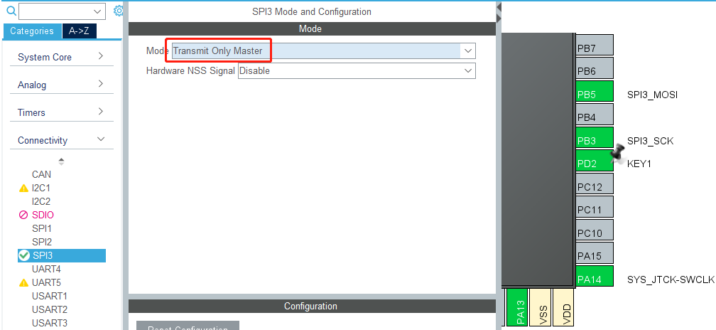
- Set the mode of SPI3 to Transmit Only Master, so that the PB5 pin will be automatically set to SPI3_MOSI.
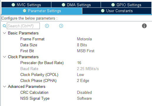
- Modify the parameters of data sent by SPI3, refer to the following pictures for specific parameters.
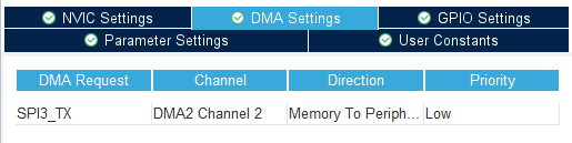
- Add DMA settings for SPI3_TX.
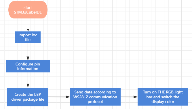
8.3. Analysis of the experimental flow chart
8.4. core code explanation
- Create new bsp_rgb.h and bsp_rgb.c, and add the following content to bsp_rgb.h:
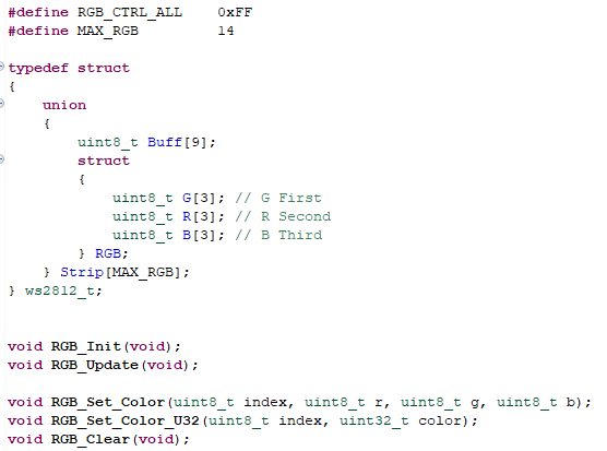
Among them, the ws2812_t structure is used to store the cache data of the light bar.
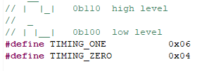
- Create the following content in the bsp_rgb.c file: According to the communication protocol of WS2812, use the three bits of SPI to simulate one bit of WS2812. When the value of the SPI output three bits is 0b110, it corresponds to the high level of WS2812, and when the SPI output three bits are 0b100, it corresponds to the low level of WS2812.
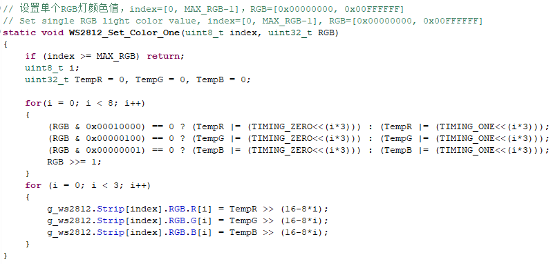
- The WS2812_Set_Color_One() function sets the color value of a single RGB lamp, index=[0, MAX_RGB-1], RGB=[0x00000000, 0x00FFFFFF], the arrangement of RGB values: red is at the front, green in the middle, and blue at the end.
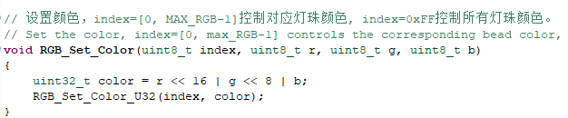
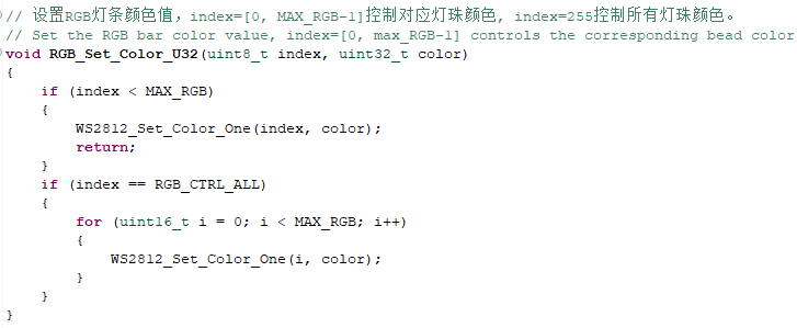
- RGB_Set_Color(index, r, g, b) and RGB_Set_Color_U32(index, color) set the color value of the RGB light bar, index=[0, MAX_RGB-1] controls the color of the corresponding light beads, and index=255 controls the color of all light beads.
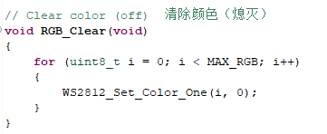
- RGB_Clear() clears the RGB light cache.
- The RGB_Update() function refreshes the color of the RGB light bar. After changing the color of the RGB lamp, you must call the RGB_Update() function to refresh the display, otherwise the product will not work.

- Send data using SPI3 DMA.

8.5. Hardware connection
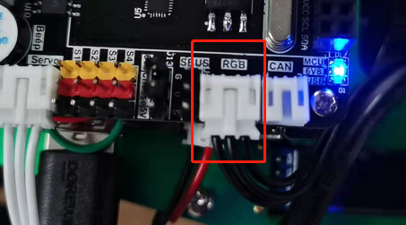
Since the RGB light bar needs to be connected to the position of the RGB light bar on the expansion board, the interface has been set to prevent reverse connection, and you can find the interface and insert it in the correct direction.
8.6. Experimental effect
After the program is programmed, the LED light flashes once every 200 milliseconds, and the RGB light bar will display red, green, and blue in sequence, switching a color every 500 milliseconds.