Welcome to ROSMASTER X3 Plus repository
11.6 Pure visual 2D mapping
6. Pure visual 2D mapping navigation
6. Pure visual 2D mapping navigation6.1. Introduction6.2. Use6.2.1. Map construction6.2.2. Controlling the robot6.2.3. Map saving6.2.4. Navigation6.3. Topics and services6.4. Configuration parameters6.5, TF transformation
depthimage_to_laserscan: http://wiki.ros.org/depthimage_to_laserscan
depthimage_to_laserscan source code: https://github.com/ros-perception/depthimage_to_laserscan
6.1. Introduction
depthimage_to_laserscan takes a depth image (float encoded meters or preferably uint16 encoded millimeters for OpenNI devices) and generates a 2D laser scan based on the provided parameters. depthimage_to_laserscan uses delayed subscription, which does not subscribe to image or camera information until a user scans.
The depthimage_to_laserscan function package converts depth images into lidar data, and its mapping and navigation functions are the same as lidar. Note: The scanning range of the depth camera is not 360°.
6.2. Use
Note: Pure depth mapping navigation in this section does not work well and is not recommended.
Note: When building a map, the slower the speed, the better the effect (note that the rotation speed should be slower). If the speed is too fast, the effect will be poor.
According to different models, you only need to set the purchased model in [.bashrc], X1 (normal four-wheel drive) X3 (Mailun) Take X3 as an example
#Raspberry Pi 5 master needs to enter docker first, please perform this step#If running the script into docker fails, please refer to ROS/07, Docker tutorial~/run_docker.shOpen the [.bashrc] file
xxxxxxxxxxsudo vim .bashrc
Find the [ROBOT_TYPE] parameters and modify the corresponding car model
xxxxxxxxxxexport ROBOT_TYPE=X3 # ROBOT_TYPE: X1 X3 X3plus R2 X76.2.1. Map construction
Start command (robot side)
xxxxxxxxxxroslaunch yahboomcar_nav astrapro_bringup.launch
<PI5 needs to open another terminal to enter the same docker container
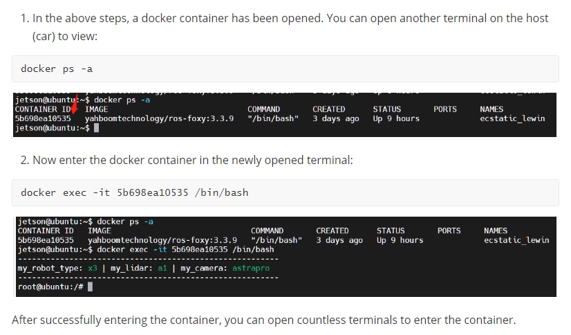
Mapping command (robot side)
xxxxxxxxxxroslaunch yahboomcar_nav yahboomcar_map.launch use_rviz:=false map_type:=gmapping[use_rviz] parameter: whether to enable rviz visualization.
[map_type] parameter: Set the mapping algorithm [gmapping].
Turn on the visual interface (virtual machine side)
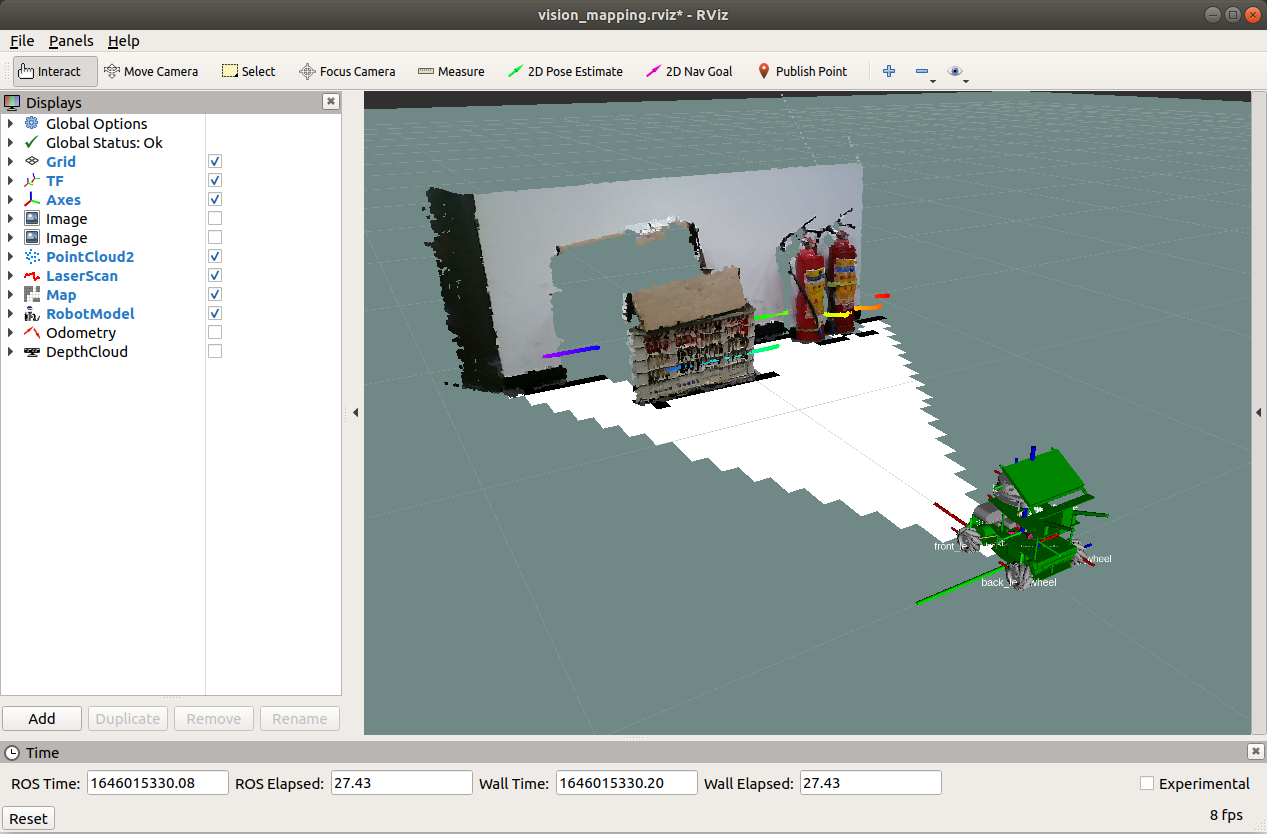
xxxxxxxxxxroslaunch yahboomcar_nav view_vision_mapping.launch
6.2.2. Controlling the robot
Keyboard controls robot movement
xxxxxxxxxxrosrun teleop_twist_keyboard teleop_twist_keyboard.py # System integrationroslaunch yahboomcar_ctrl yahboom_keyboard.launch # CustomControl the robot movement with the handle
There may be some scattered points during the mapping process. If the mapping environment is well closed, relatively regular, and the movement is slow, the scattering phenomenon will be much smaller.
6.2.3. Map saving
xxxxxxxxxxrosrun map_server map_saver -f ~/yahboomcar_ws/src/yahboomcar_nav/maps/my_map # The first waybash ~/yahboomcar_ws/src/yahboomcar_nav/maps/map.sh # The second wayThe map will be saved to the ~/yahboomcar_ws/src/yahboomcar_nav/maps/ folder, a pgm image and a yaml file.
map.yaml
xxxxxxxxxximage: map.pgmresolution: 0.05origin: [-15.4,-12.2,0.0]Negate: 0occupied_thresh: 0.65free_thresh: 0.196Parameter analysis:
image: The path of the map file, which can be an absolute path or a relative path.
resolution: resolution of the map, meters/pixel
Origin: 2D pose (x, y, yaw) in the lower left corner of the map. The yaw here is rotated counterclockwise (yaw=0 means no rotation). Many parts of the current system ignore the yaw value.
negate: whether to reverse the meaning of white/black and free/occupied (the interpretation of the threshold is not affected)
occupied_thresh: Pixels with an occupation probability greater than this threshold will be considered fully occupied.
free_thresh: Pixels with occupancy probability less than this threshold will be considered completely free.
6.2.4. Navigation
Start command (robot side)
xxxxxxxxxxroslaunch yahboomcar_nav astrapro_bringup.launch
<PI5 needs to open another terminal to enter the same docker container
Navigation commands (robot side)
xxxxxxxxxxroslaunch yahboomcar_nav yahboomcar_navigation.launch use_rviz:=false map:=house[use_rviz] parameter: whether to enable rviz visualization.
[map_type] parameter: Set the mapping algorithm [gmapping].
Turn on the visual interface (virtual machine side)
xxxxxxxxxxroslaunch yahboomcar_nav view_navigate.launch
Single point navigation
Use the [2D Pose Estimate] of the [rviz] tool to set the initial pose until the position of the car in the simulation is consistent with the position of the actual car.
Click [2D Nav Goal] of the [rviz] tool, and then select a target point on the map where there are no obstacles. Release the mouse to start navigation. Only one target point can be selected, and it will stop when it is reached.
Multi-point navigation
Same as the first step of single-point navigation, first set the initial pose of the car.
Click [Publish Point] of the [rviz] tool, and then select the target point on the map where there are no obstacles. Release the mouse to start navigation. You can click [Publish Point] again, and then select the point, and the robot will click on it. Cruising between points.
When using the [2D Pose Estimate] tool of the [rviz] tool to set the initial pose of the car, the multi-point navigation function is automatically canceled.
6.3. Topics and services
| Subscription topic | Type | Description |
|---|---|---|
| image | sensor_msgs/Image | Input image. This can be in floating point or raw uint16 format. For OpenNI devices, uint16 is the native representation and is more efficient to handle. This is usually /camera/depth/image_raw. If your image is distorted, you should remap this theme to image_rect. OpenNI cameras typically have very little distortion, so correction can be skipped for this application. |
| camera_info | sensor_msgs/CameraInfo | Camera information for the associated image. |
| Post Topic | Type | Description |
| scan | sensor_msgs/LaserScan | Output laser scan. and will output a range array containing NAN and +-INF. |
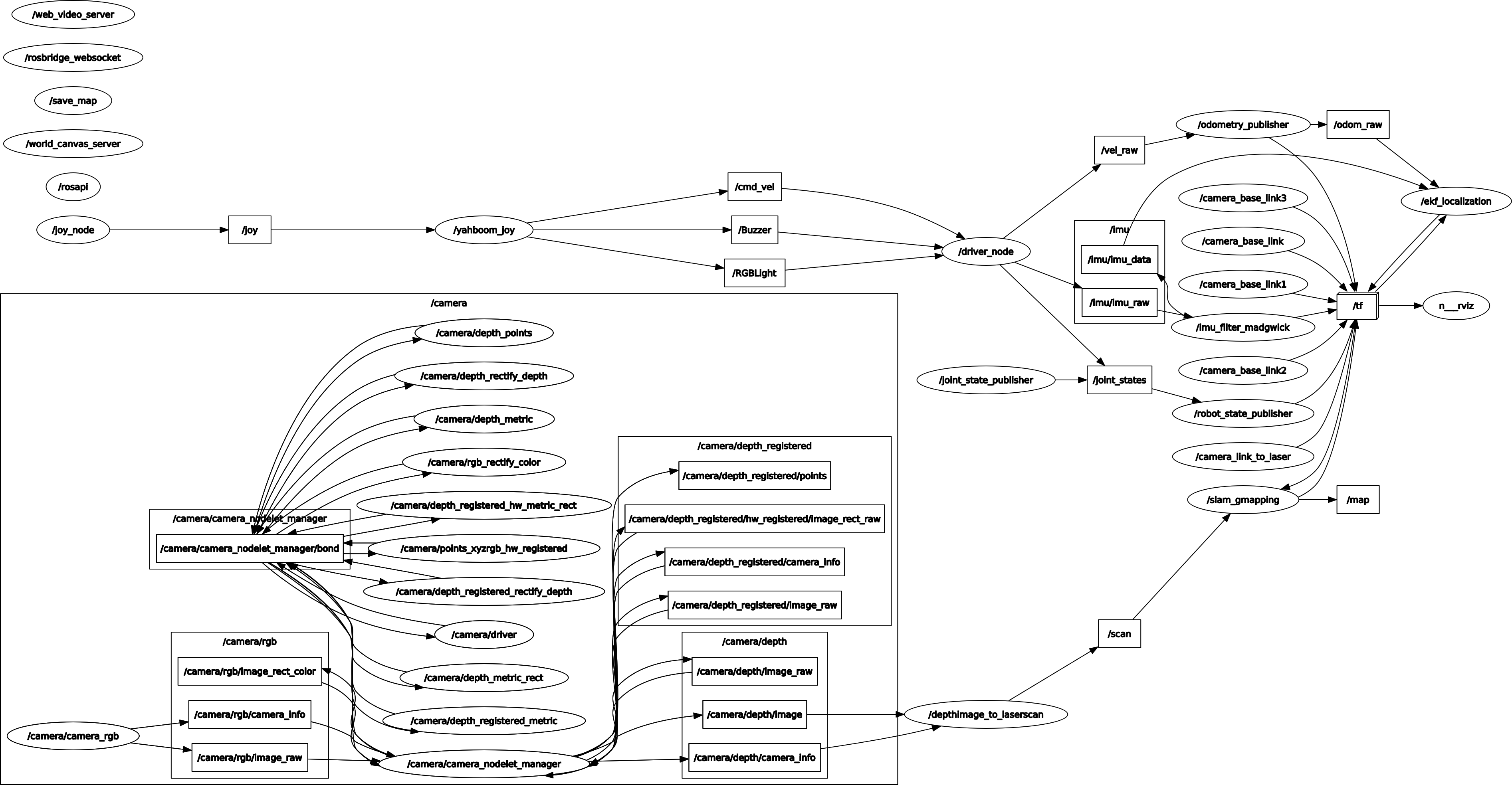
Node view
xxxxxxxxxxrqt_graph
6.4. Configuration parameters
| Parameters | Type | Default value | Description |
|---|---|---|---|
| scan_height | int | 1 pixel | Number of rows of pixels used to generate the laser scan. For each column, the scan returns the minimum value of the vertically centered pixel in the image. |
| scan_time | double | 1/30.0Hz (0.033s) | Scan interval time (seconds). Typically, a rate of 1.0/frame. This value is not easily calculated from consecutive messages and is therefore set correctly by the user. |
| range_min | double | 0.45m | The minimum range returned in meters. Ranges smaller than this value will be output as -Inf. |
| range_max | double | 10.0m | The maximum range returned in meters. Ranges larger than this value will be output as +Inf. |
| output_frame_id | str | camera_depth_frame | Laser scanning frame id. For point clouds from Z-forward "optical" frames, this value should be set to the corresponding frames in X-forward and Z-up |
6.5, TF transformation
| Required TF transformation | Description |
|---|---|
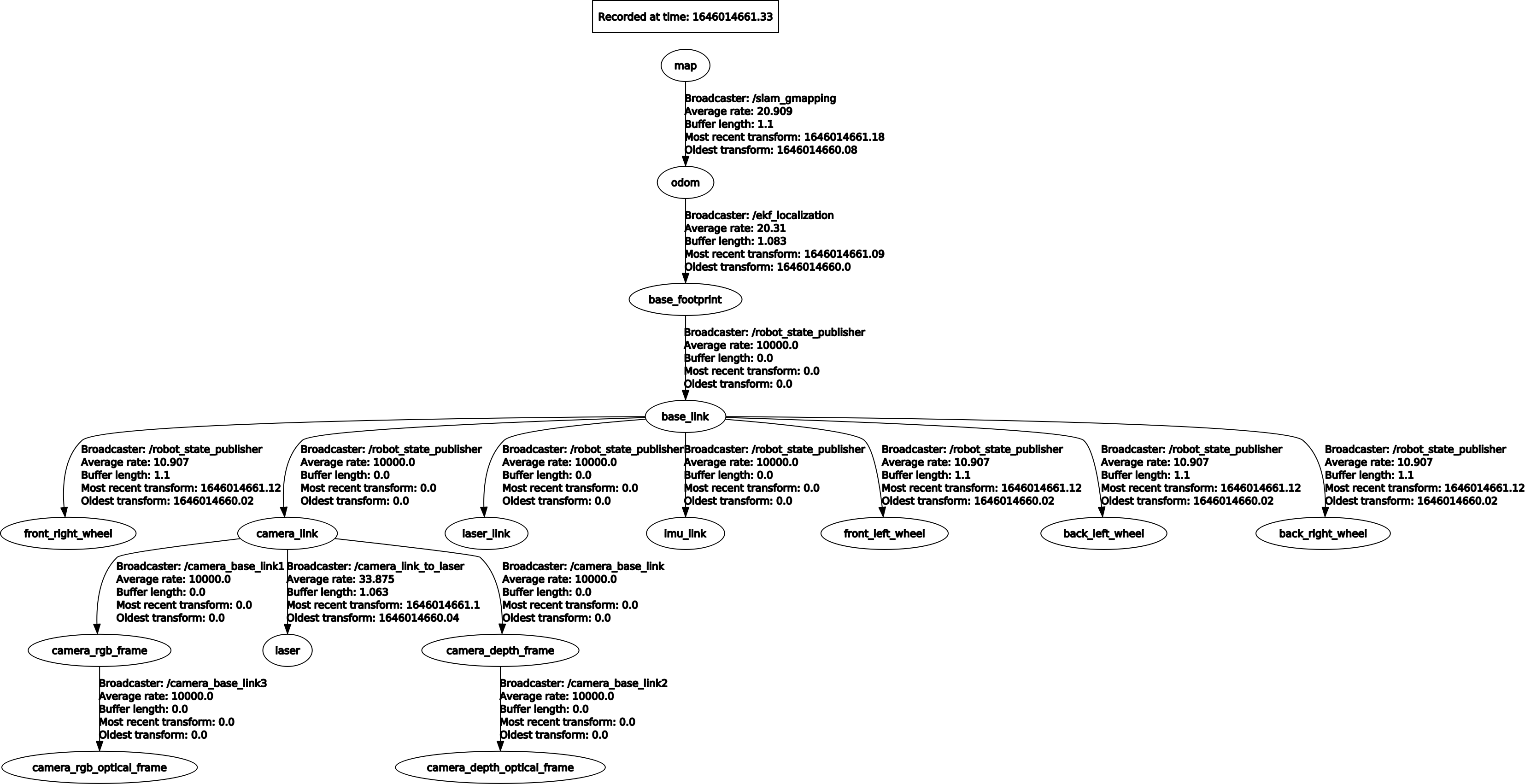
| laser-->base_link | The transformation between the laser radar coordinate system and the base coordinate system is generally published by robot_state_publisher or static_transform_publisher |
| base_link-->odom | Transformation between the map coordinate system and the robot odometer coordinate system, estimating the robot's pose in the map |
| Released TF Transform | Description |
| map-->odom | Transformation between the map coordinate system and the robot's odometry coordinate system, estimating the robot's pose in the map |
View tf tree
xxxxxxxxxxrosrun rqt_tf_tree rqt_tf_tree