Welcome to ROSMASTER X3 Plus repository
11.AMCL
11.AMCL
11.AMCL11.1 Introduction 11.2 Navigation and positioning test 11.2.1 Start 11.2.2 positioning analysis 11.2 Topics and Services 11.3 parameter configuration 11.4 coordinate transformation
11.1 Introduction
The full English name of amcl is adaptive Monte Carlo localization, which is a probabilistic localization system for two-dimensional mobile robots. In fact, it is an upgraded version of the Monte Carlo positioning method, which uses an adaptive KLD method to update particles and uses particle filters to track the robot's pose based on a known map. As currently implemented, this node is only available for laser scans and laser maps. It can be extended to process other sensor data. amcl receives laser-based maps, laser scans, and transformation information, and outputs pose estimates. On startup, amcl initializes its particle filter according to the provided parameters. Note that due to the default settings, if no parameters are set, the initial filter state will be a medium-sized particle cloud centered at(0,0,0).
Monte Carlo
- Monte Carlo method, also known as statistical simulation method and statistical experiment method, is an idea or method. It is a numerical simulation method that takes probability phenomena as the research object. It is sampling survey a calculation method for estimating unknown characteristic quantities by obtaining statistical values
- Example: There is an irregular shape in a rectangle, how to calculate the area of the irregular shape? Not good. But we can approximate. Take a bunch of beans, spread them evenly on the rectangle, and count the number of beans in the irregular shape and the number of beans in the rest. The area of the rectangle is known, so the area of the irregular shape is obtained by estimation. In terms of robot positioning, it is possible to be in any position on the map. How can we express the confidence of a position in this case? We also use particles, and where there are more particles, it means the robot is more likely to be there.
The biggest advantage of Monte Carlo method
- The error is independent of the dimensionality of the problem.
- Problems with statistical properties can be solved directly.
- Discretization is not necessary for continuous problems
Disadvantages of Monte Carlo Method
- Deterministic problems need to be transformed into random problems.
- Errors are probabilistic errors.
- Usually requires more calculation steps N.
particle filter
- The number of particles represents how likely something is. Change the distribution of particles through some evaluation method(evaluate the possibility of this thing). For example, in robot positioning, for a certain particle A, I think the possibility of this particle at this coordinate(for example, this coordinate belongs to the "this thing" mentioned earlier) is very high, so I will give it a high score. Next time you rearrange the positions of all the particles, place more around this position. After a few more rounds like this, the particles will all be concentrated to the position with a high probability.
Adaptive Monte Carlo
- Solved the robot kidnapping problem, it will re-sprinkle some particles globally when the average score of the particles is suddenly reduced(meaning that the correct particles are discarded in a certain iteration).
- Solved the problem of fixed number of particles, because sometimes when the robot positioning is almost obtained, for example, these particles are concentrated in one piece, it is not necessary to maintain so many particles, and the number of particles can be less at this time.
11.2 Navigation and positioning test
According to different models, you only need to set the purchased model in [.bashrc], X1(ordinary four-wheel drive) X3(Mike wheel) X3plus(Mike wheel mechanical arm) R2(Ackerman differential) and so on, to X3 for example.
Open the [.bashrc] file
sudo vim .bashrc
Find the [ROBOT_TYPE] parameter and modify the corresponding model
xxxxxxxxxxexport ROBOT_TYPE=X3 # ROBOT_TYPE: X1 X3 X3plus R2 X7
11.2.1 Start
Start the driver(robot side), for the convenience of operation, this section takes [mono + laser + yahboomcar] as an example.
x#You need to enter docker first, perform this step more#If running the script to enter docker fails, please refer to 07.Docker-orin/05, Enter the robot's docker container~/run_docker.shroslaunch yahboomcar_nav laser_bringup.launch # laser + yahboomcar roslaunch yahboomcar_nav laser_usb_bringup.launch # mono + laser + yahboomcar roslaunch yahboomcar_nav laser_astrapro_bringup.launch # Astra + laser + yahboomcar Start the navigation obstacle avoidance function(robot side), you can set parameters and modify the launch file according to your needs.
<Open another terminal and enter the same docker container
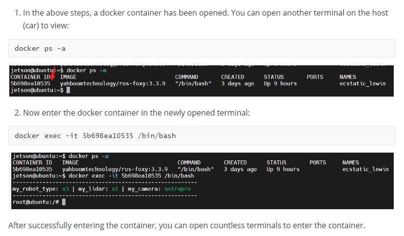
xxxxxxxxxxroslaunch yahboomcar_nav yahboomcar_navigation.launch use_rviz:=false map:=house
- [use_rviz] parameter: whether to open rviz.
- [map] Parameters: map name, the map to be loaded.
Open the visual interface(virtual machine side)
xxxxxxxxxxroslaunch yahboomcar_nav view_navigate.launch

11.2.2 positioning analysis

The position of amcl in the upper left corner of the navigation frame, its role is to tell the robot where.
After opening it, we can see that a handful of green particles are evenly scattered around the robot. When we randomly move the robot(keyboard or mouse control), all the particles move with it. Use the position of each particle to simulate a sensor information and compare it with the observed sensor information(usually a laser), thereby assigning a probability to each particle. Then, the particles are regenerated according to the generated probability, and the higher the probability, the greater the probability of generation. After such iterations, all the particles will slowly converge together, and the exact position of the robot is calculated.
11.2 Topics and Services
| Subscribe to topics | type | describe |
|---|---|---|
| scan | sensor_msgs/LaserScan | Lidar data |
| tf | tf/tfMessage | Coordinate transformation information |
| initialpose | geometry_msgs/PoseWithCovarianceStamped | Mean and covariance used to(re)initialize the particle filter. |
| map | nav_msgs/OccupancyGrid | When the use_map_topic parameter is set, AMCL subscribes to this topic to retrieve maps for laser-based positioning. New in Navigation 1.4.2. |
| Post a topic | type | describe |
| amcl_pose | geometry_msgs/PoseWithCovarianceStatmped | Pose estimation of the robot in the map, with covariance information |
| particlecloud | geometry_msgs/PoseArray | A collection of pose estimates maintained by particle filters |
| tf | tf/tfMessage | Post the conversion from odom to map |
| Server | type | describe |
| global_localization | std_stvs/Empty | Initialize global positioning, all particles are randomly scattered on the free area on the map |
| request_normotion_update | std_stvs/Empty | Perform the update manually and publish the updated particles |
| set_map | nav_msgs/SetMap | A service to manually set up new maps and poses. |
| client | type | describe |
| static_map | nav_msgs/GetMap | amcl calls this service to retrieve maps for laser positioning; start prevents maps from being fetched from this service. |
View Nodes
xxxxxxxxxxrosrun rqt_graph rqt_graph

11.3 parameter configuration
There are three categories of ROS parameters that can be used to configure amcl nodes: global filters, laser models, and odometer models.
- Overall filter parameters
| parameter | type | Defaults | describe |
|---|---|---|---|
| ~min_particles | int | 100 | Minimum number of particles allowed |
| ~max_particles | int | 5000 | maximum number of particles allowed |
| ~kld_err | double | 0.1 | Maximum error between true distribution and estimated distribution |
| ~ kld_z | double | 0.99 | The upper standard normal quantile of(1-p), where p is the probability that the estimated distribution error is less than kld_err |
| ~update_min_d | double | 0.2(m) | The translation distance required to perform a filter update |
| ~update_min_a | double | ft/6.0(rad) | Rotational movement required to perform a filter update |
| ~reseample_interval | int | 2 | number of filter updates before resampling |
| ~transform_tolerance | double | 0.1(s) | When to publish the transform to indicate that this transform is valid in the future |
| ~recovery_alpha_slow | double | 0.0 | Exponential decay rate of the slow average weight filter used to decide when to resume operations by adding random poses, 0.0 disables |
| ~recovery_alpha_fast | double | 0.0 | Exponential decay rate of the fast average weight filter used to decide when to resume operations by adding random poses, 0.0 disables |
| ~initial_pose_x | double | 0.0(m) | Initial pose mean(x), used to initialize the Gaussian filter |
| ~initial_pose_y | double | 0.0(m) | Initial pose mean(y), used to initialize the Gaussian filter |
| ~initial_pose_a | double | 0.0(m) | Initial pose mean(yaw), used to initialize the Gaussian filter |
| ~ initial_cov_xx | double | 0.5*0.5(m) | Initial pose mean(x*x), used to initialize the Gaussian distribution filter |
| ~ initial_cov_yy | double | 0.5*0.5(m) | Initial pose mean(y*y), used to initialize the Gaussian filter |
| ~ initial_cov_aa | double | (ft/12)*(ft/12)(rad) | Initial pose mean(yaw*yaw), used to initialize the Gaussian distribution filter |
| ~gui_publish_rate | double | -1.0(Hz) | When visualizing, the maximum rate at which information is published, -1.0 means disable |
| ~save_pose_rate | double | 0.5(Hz) | the parameter server and covariance initial_cov for subsequent initialization filters. -1.0 means disable |
| ~use_map_topic | bool | false | When set to true, amcl will subscribe to the map topic instead of receiving maps via service calls |
| ~first_map_only | bool | false | When set to true, amcl will only use the first map it subscribes to, not the map it receives with each update |
| ~selective_resampling | bool | false | When set to true, will reduce the resampling rate when not needed and help avoid particle deprivation. Resampling occurs only when the effective number of particles(N_eff=1/(sum(k_i^2)) is less than half of the current number of particles. |
- Laser Model Parameters
| parameter | type | Defaults | describe |
|---|---|---|---|
| ~laser_min_range | double | -1.0 | Minimum scan range, set -1, the minimum usage range reported by the lidar. |
| ~laser_max_range | double | -1.0 | Maximum scan range, set -1, the maximum usage range reported by the lidar. |
| ~laser_max_beams | int | 30 | How many evenly spaced beams to use in each scan when updating the filter |
| ~ laser_z_bit | double | 0.95 | Mixed weights for the z_bit part of the model |
| ~laser_z_short | double | 0.1 | Mixed weights for the z_short part of the model |
| ~laser_z_max | double | 0.05 | Mixed weights for the z_max part of the model |
| ~laser_z_rand | double | 0.05 | Mixed weights for the z_rand part of the model |
| ~laser_sigma_hit | double | 0.2(m) | Standard deviation of the Gaussian model used in the z_hit part of the model |
| ~laser_lambda_short | double | 0.1 | Exponential decay parameter for the z_short part of the model |
| ~laser_likelihood_max_dist | double | 2.0(m) | Measure the maximum distance on the map that the obstacle swells |
| ~laser_model_type | string | "likelihood_field" | Model selection, bean, likelihood_field or likelihood_field_prob |
- Odometer Model Parameters
| parameter | type | Defaults | describe |
|---|---|---|---|
| ~odom_model_type | string | "diff" | Model selection, diff, omni, diff-corrected or omni-corrected |
| ~odom_alpha1 | double | 0.2 | Specifies the expected noise in the odometry rotation estimate based on the rotational component of the robot's motion |
| ~odom_alpha2 | double | 0.2 | Specifies the expected noise in the odometry rotation estimate based on the translational component of the robot's motion |
| ~odom_alpha3 | double | 0.2 | Specifies the expected noise in the odometry translation estimate based on the translational component of the robot's motion |
| ~odom_alpha4 | double | 0.2 | Specifies the expected noise in the odometry translation estimate based on the rotational component of the robot's motion |
| ~odom_alpha5 | double | 0.2 | Translation-dependent noise parameter(only used in model omni) |
| ~odom_frame_id | string | "odom" | The coordinate system of the odometer |
| ~base_frame_id | string | "base_link" | The coordinate system of the robot chassis |
| ~global_frame_id | string | "map" | Coordinate system published by the positioning system |
| ~tf_broadcast | bool | true | When set to false, amcl will not publish the coordinate system transformation between map and odom |
11.4 coordinate transformation

Compare the two methods Odometry Localization and AMCL Map Localization:
Odometry Localization: The speed of the wheel can be known through the encoder feedback of the motor, the current speed of the wheel can be obtained according to the radius of the wheel, the overall moving speed of the robot can be obtained according to the forward kinematics model, and the movement can be obtained by integrating according to time. total mileage.
AMCL Map Localization: In amcl, the pose information of the base_frame corresponding to the map_frame has been obtained through particle filter positioning, but in order to ensure that the base_frame has only one parent node, the conversion will not be published directly, because the parent node of the base_frame is already odom_frame, then amcl can only publish the conversion of map_frame to odom_frame, which also has the advantage that we can get the cumulative error of odom.
We have been saying that the distance measurement information obtained by the wheel odometer will have a cumulative error, which is similar to the car slipping. If only the wheel odometer is used to calculate the moving distance, there will be an error:

For example: the robot walks straight ahead, and the result obtained by the wheel odometer should be 1 meter, then the distance from odom_frame should be 1 meter, but due to the slipping in place, in fact, the robot does not move at all through amcl positioning, then amcl needs to publish the conversion of map_frame to odom_frame to remove this 1-meter error, so as to maintain the normality of the entire tf tree.
The transformation relationship between coordinates.
xxxxxxxxxxrosrun rqt_tf_tree rqt_tf_tree

As can be seen from the above figure, the coordinate conversion from map->odom is completed by the amcl node.