yahboom
HomeLearn
Solution
Blog
Online Store
About Us
EN/中文
ROSMASTER X3 Plus📖
1.Preparation and First Trial
  • 1.1 Wiring Introduction
  • 1.2 Precautions for battery
  • 1.3 First Trial
  • 1.4 Precautions for DIY Robotic Arm
2. Assembly steps
  • Installation Video
3.Remote control course
  • 3.1 APP remote control
  • 3.2 Model aircraft remote control
  • 3.3 Handle remote control
4.Hardware course
  • 4.1 About expansion board_V3.0
  • 4.1 About expansion board_V1.0
  • 4.2 STM32 Development
  • 4.3 Button to control the buzzer
  • 4.4 FreeRTOS application
  • 4.5 Serial communication
  • 4.6 SBUS model aircraft remote control
  • 4.7 CAN bus communication
  • 4.8 RGB colorful light bar
  • 4.9 Timer interrupt to control
  • 4.10 Control serial port servos
  • 4.11 Nine-axis attitude sensor
  • 4.12 Control motor
  • 4.13 Timer captures the encoder data
  • 4.14 Kinematic Analysis
  • 4.15 PID control robot movement
5.Basic course
  • 5.1 Update the firmware
  • 5.2 Turn off the self-starting process
  • 5.3 Install the Rosmaster driver
  • 5.4 Buzzer whistle
  • 5.5 Control PWM servo
  • 5.6 RGB colorful light bar
  • 5.7 Control motor
  • 5.8 Control robot movement
  • 5.9 Control Serial Servo
6.Linux operating system
  • 6.1 Virtual machine installation
  • 6.2 Linux basics
  • 6.3 Remote control
  • 6.4 Multi-machine communication
  • 6.5 Static IP and hotspot mode
  • 6.6 Bind the device ID
  • 6.7 Web page real-time monitor
  • 6.8 Expansion tutorial
  • 6.9.1 Jetson Nano write sytem
  • 6.9.2 Jetson Xavier NX write system
  • 6.9.3 Jetson TX2 NX write system
  • 6.9.4 Raspberry Pi write system
7.Docker-Just for pi5
  • 7.1 Docker overview and docker installation
  • 7.2 Common commands for docker image containers
  • 7.3 Docker images deeply understand and publish images
  • 7.4 Docker hardware interaction and data processing
  • 7.5 Enter the bot's docker container
  • 7.6 Robot development environment construction in Docker
  • 7.7 How customers can update docker images in the future
8.ROS basic course
  • 8.1 ROS introduction
  • 8.2 ROS installation
  • 8.3 ROS common command tools
  • 8.4 ROS workspace
  • 8.5 ROS function package
  • 8.6 ROS node
  • 8.7 ROS topic publisher
  • 8.8 ROS topic subscribers
  • 8.9 ROS service client
  • 8.10 ROS service server
  • 8.11 ROS action client
  • 8.12 ROS action server
  • 8.13 ROS custom message reception
  • 8.14 ROS-launch file
  • 8.15 ROS-TF transformation
  • 8.16 ROS parameter service
  • 8.17 ROS-rviz use
  • 8.18 ROS-rqt tool usage
  • 8.19 Topic message recording and playback
  • 8.20 urdf model introduction
  • 8.21 gazebo introduction
  • 8.22 ROS distributed communication
9.OpenCV courses
  • 9.1 Getting started with Open Source CV
  • 9.2 Geometric transformation
  • 9.3 Image processing and draw
  • 9.4 Image beautification
  • 9.5 Opencv application
  • 9.6 AR vision
  • 9.7 AR QR code
  • 9.8 ROS+Opencv foundation
  • 9.9 ROS+Opencv application
  • 9.10 Data transformation
  • 9.11 MediaPipe development
10.Robot control course
  • 10.1 PID algorithm theory
  • 10.2 Robot PID debugging
  • 10.3 Robot information release
  • 10.4 Robot keyboard control
  • 10.5 Robot handle control
  • 10.6 Robot state estimation
  • 10.7 Robot calibration
  • 10.8 Robot URDF model
11.Depth camera course
  • 11.1 How to use the Astra camera
  • 11.2 Astra camera calibration
  • 11.3 Astra Color Tracking
  • 11.4 Astra Object Tracking
  • 11.5 Visual tracking autopilot
  • 11.6 Pure visual 2D mapping
  • 11.7 RTAB-Map 3D mapping
  • 11.8 ORB_SLAM2 basics
  • 11.9 ORB_SLAM2_Octomap
12.Lidar course
  • 12.1 Lidar basic-SLAM
  • 12.1 Lidar basic-EAI
  • 12.2 Lidar avoiding
  • 12.3 Lidar guard
  • 12.4 Lidar follow
  • 12.5 Patrol game
  • 12.6 gmapping mapping algoritm
  • 12.7 hector mapping algorithm
  • 12.8 karto mapping algorithm
  • 12.9 cartographer mapping
  • 12.10 rrt_exploration mapping
  • 12.11 AMCL
  • 12.12 Navigation and avoiding
  • 12.13 APP mapping and navigation
13.Multi-robot control course
  • 13.1 Multi-machine handle control
  • 13.2 Multi-machine navigation
  • 13.3 Multi-machine formation
  • 13.4 Multi-machine surround
14.Deep learning courses
  • 14.1 KNN recognizes handwritten
  • 14.2 Basic use of TensorFlow
  • 14.3 Basic use of PyTorch(jetson)
  • 14.4 yolov5 model training(jetson)
  • 14.5 yolov5+tensorrt acceleration
  • 14.6 yolov4-tiny
15.Voice control courses
  • 0. How to use old voice module in new image
  • 15.1 Introduction of voice control-new
  • 15.2 Voice control module port-new
  • 15.3.Introduction of voice module-old
  • 15.4.Voice control module port binding-old
  • 15.5 Voice control car movement
  • 15.6 Voice control Autopilot
  • 15.7 Voice control color recogzition
  • 15.8 Voice control color tracking
  • 15.9 Voice control multi-point nagavation
16.Robotic arm control course
  • 16.1 MoveIt configuration
  • 16.2 MoveIt control the real machine
  • 16.3 MoveIt moves randomly
  • 16.4 MoveIt kinematics design
  • 16.5 MoveIt cartesian path
  • 16.6 MoveIt avoiding
  • 16.7 MoveIt scene design
  • 16.8 MoveIt trajectory planning
  • 16.9 Mediapipe palm control car
  • 16.10 Mediapipe gesture control robotic arm
  • 16.11 Mediapipe gesture control car
  • 16.12 Mediapipe arm attitude control robotic arm
  • 16.13 Mediapipe recognizes and tracks palm control robotic arm
  • 16.14 Recognizes color block and handling
  • 16.15 Autopilot to clear obstacles
17.Voice control robotic arm course
  • 17.1 Voice control robotic arm movement
  • 17.2 Voice control robotic arm learning
  • 17.3 Voice control color block transport
  • 17.4 Voice control robotic arm grip objects
  • 17.5 Voice control robotic arm garbage sorting
18.Model training Autopilot
  • 18.0 ReadMe
  • 18.1 yolov5 to train traffic signs
  • 18.2 TensorRt acceleration identification mark
  • 18.3 Road sign indication function description
  • 18.4 Collect data
  • 18.5 Training model
  • 18.6 Model transformation and application
  • 18.7 AI Autopilot
19.For Orin-Remote control course
1. APP control
  • 1. APP control
  • 2. Model aircraft control
  • 3. Handle control
2. Model aircraft control
3. Handle control
20.Orin-Hardware course
  • 1. About expansion board_V1.0
  • 1. About expansion board_V2.0
  • 2. STM32 Development environment
  • 3. Button control
  • 4. FreeRTOS application
  • 5. Serial communication
  • 6. SBUS model aircraft remote control
  • 7. CAN bus communication
  • 8. RGB colorful light bar
  • 9. Timer interrupt to control PWM servo
  • 10. Control serial port servos
  • 11. Nine-axis attitude sensor to obtain data
  • 12. Control motor
  • 13. Timer captures the encoder data
  • 14. Robot kinematics analysis theory
  • 15. PID control robot movement
21.Orin-Basic course
  • 1. Update the firmware
  • 2. Turn off the self-starting process at startup
  • 3. Install the Rosmaster driver library
  • 4. Buzzer whistle
  • 5. Control PWM servo
  • 6. RGB colorful light bar special effects display
  • 7. Control motor
  • 8. Control robot movement
  • 9. Control Serial Servo
22.Orin-Linux operating systemnew
  • 1. Virtual machine installation and use
  • 2. Linux basics
  • 3. Remote control
  • 4. Multi-machine communication configuration
  • 5. Static IP and hotspot mode
  • 6. Bind the device ID
  • 7. Web page real-time monitoring
  • 8. Expansion tutorial
  • 9.1 Jetson Nano write sytem
  • 9.2 Jetson Xavier NX write system
  • 9.3 Jetson TX2 NX-Orin series write system
  • 9.4 Raspberry Pi write system
  • 10.Jetpack old system upgraded to SUPER system
23.Orin-Dockernew
SUPER image uses ros environment in docker
  • 1、Docker overview and docker installationnew
  • 2、Common commands for docker image containersnew
  • 3、Docker images deeply understand and publish imagesnew
  • 4、Docker hardware interaction and data processingnew
  • 5、Enter the bot's docker containernew
  • 6、Robot development environment construction in Dockernew
23.Orin-ROS basic course
  • 1.ROS introduction
  • 2.Project file structure
  • 3.Common commands and tools
  • 4.Publisher
  • 5.Subscribers
  • 6.Customize topic messages and use
  • 7.Client
  • 8.Server
  • 9.Custom service messages and usage
  • 10.TF release and monitoring
24.Orin-OpenCV courses
  • 1. Getting started with Open Source CV
  • 2. Open Source CV geometric transformation
  • 3. Open Source CV image processing and drawing text line segments
  • 4. Open Source CV image beautification
  • 5. Opencv application
  • 6. AR vision
  • 7. AR QR code
  • 8. ROS+Opencv foundation
  • 9. ROS+Opencv application
  • 10. Data transformation and point cloud
  • 11. MediaPipe development
25.Orin-Robot control course
  • 1.PID algorithm theory
  • 2.Robot PID debugging
  • 3.Robot information release
  • 4.Robot keyboard control
  • 5.Robot handle control
  • 6.Robot state estimation
  • 7.Robot calibration
  • 8.Robot URDF model
26.Orin-Depth camera course
  • 01.How to use the Astra camera
  • 02.Astra camera calibration
  • 03.Astra Color Tracking
  • 04.Astra Object Tracking
  • 05.Visual tracking autopilot
  • 06.Pure visual 2D mapping and navigation
  • 07.RTAB-Map 3D mapping navigation
  • 08.ORB_SLAM2 basics
  • 09.ORB_SLAM2_Octomap
27.Orin-Lidar course
  • 1.Lidar basic-4ROS-EAI
  • 1.Lidar basic-SLAM
  • 2.Lidar avoiding
  • 3.Lidar guard
  • 4.Lidar follow
  • 5.Patrol game
  • 6.gmapping mapping algorithm
  • 7.hector mapping algorithm
  • 8.karto mapping algorithm
  • 9.cartographer mapping algorithm
  • 10.rrt_exploration mapping algorithm
  • 11.AMCL
  • 12.Navigation and avoiding
  • 13.APP mapping and navigation
28.Orin-Multi-robot control course
  • 1.Multi-machine handle control
  • 2.Multi-machine navigation
  • 3.Multi-machine formation
  • 4.Multi-machine surround
29.Orin-Deep learning courses
  • 1.KNN recognizes handwritten digits
  • 2.Basic use of TensorFlow
  • 3.Basic use of PyTorch(jetson)
  • 4.YOLOv11Model conversion(SUPER)new
  • 5.YOLOv11Dataset annotation(SUPER)new
  • 6.YOLOv11Model conversion + tensorrt acceleration(SUPER)new
  • 7.YOLOv11Object recognition(SUPER)new
30.Orin-Voice control courses
  • 0. How to use old voice module in new image
  • 1.1 Introduction of voice module-new
  • 1.2 Introduction of voice module-old
  • 2.1 Voice control module port binding-new
  • 2.2 Voice control module port binding-old
  • 3. Voice control car movement
  • 4. Voice control Autopilot
  • 5. Voice control color recognition
  • 6. Voice control color tracking
  • 7. Voice control multi-point navigation
31.Orin-Robotic arm control course
  • 1.MoveIt configuration(VM)
  • 2.MoveIt control the real machine(VM)
  • 3.MoveIt moves randomly(VM)
  • 4.MoveIt kinematics design(VM)
  • 5.MoveIt cartesian path(VM)
  • 6.MoveIt avoiding(VM)
  • 7.MoveIt scene design(VM)
  • 8.MoveIt trajectory planning(VM)
  • 9.Mediapipe palm control car
  • 10.Mediapipe gesture control robotic arm
  • 11.Mediapipe gesture control car
  • 12.Mediapipe arm attitude control robotic arm
  • 13.Mediapipe recognizes and tracks palm control robotic arm
  • 14.Recognizes color block and handling
  • 15.Autopilot to clear obstacles
32.Orin-Voice control robotic arm course
  • 1.Voice control robotic arm movement
  • 2.Voice control robotic arm learning
  • 3.Voice control color block transport
  • 4.Voice control robotic arm grip objects
  • 5.Voice control robotic arm garbage sorting
LLM tutorial
1.Development environment
  • 0. Model usage instructions
  • 1.Environments deployment
  • 2.Dialogue platform installation
2.Jetson Nano B01
  • 1.Qwen2 model
  • 2.TinyLlama model
  • 3.Phi-3 model
  • 4.Gemma model
  • 5.Orca Mini model
  • 6.StarCoder2 model
  • 7.DeepSeek-R1 model
  • 8.Expand LLaVA-Phi3
3.Jetson Orin NXNANO
  • 1.Llama3 model
  • 2.Qwen2 model
  • 3.Phi-3 model
  • 4.Gemma model
  • 5.WizardLM2 model
  • 6.Codellama model
  • 7.DeepSeek-R1 model
  • 8.Orca Mini model
  • 9.StarCoder2 model
  • 10.TinyLlama model
  • 11.Expand LLaVA
  • 12.Expand LLaVA-Phi3
4.Raspberry Pi 5B
  • 1.Meta AI Llama3 model
  • 2.Qwen2 model
  • 3.Phi-3 model
  • 4.Gemma model
  • 5.WizardLM2 model
  • 6.Meta AI Codellama model
  • 7.DeepSeek-R1 model
  • 8.Expand LLaVA
FAQ
  • Using your own Jetson board, car cannot start normally
Download
  • RemoteCtrl_APP(iOS/Android)
  • Mapping_APP(iOS_Android)
  • SystemFile_OrinNANOSUPER
  • SystemFile_OrinNXSUPER
  • SystemFile_RPi_NANO
  • Instruction Manual
  • Code
  • Autopilot Annex
  • VM software
  • Jetson_Boot_USB.tar.gz
  • Other_Annex_File
Download ZIP
FAQ
  • 1、How to connect OLED?
  • 2、Precautions for DIY Robotic Arm

Welcome to ROSMASTER X3 Plus repository

12.1 Lidar basic-EAI

1. Radar basics

1. Radar basics1.1. Overview1.2. Principle of single-line lidar1.2.1. Trigonometric ranging method1. Direct type2. Oblique shot type1.2.2. TOF time-of-flight ranging method1.3. Use radar1.3.1, 4ROS radar:1.3.2, X3/X3Pro radar:1.4, launch analysis

  • For different models of radar

xxxxxxxxxx
#Raspberry Pi 5 master needs to enter docker first, please perform this step
#If running the script into docker fails, please refer to ROS/07, Docker tutorial
~/run_docker.sh

Before using lidar, you need to declare the [RPLIDAR_TYPE] variable in advance in the [.bashrc] file according to different radar models. Open the [.bashrc] file

xxxxxxxxxx
sudo vim ~/.bashrc

If there is no sentence below in [.bashrc], you need to add it manually according to the purchased radar model. If there is this sentence, modify the radar model directly. For example: 4ROS lidar

xxxxxxxxxx
export RPLIDAR_TYPE=4ROS # a1, a2, a3, s1, s2,4ROS,X3

Note: For rosmaster series cars equipped with X3 or X3Pro radar, the startup methods of the two radars are the same, just change them to X3.

After modification, refresh the environment variables

xxxxxxxxxx
source ~/.bashrc

1.1. Overview

Single-line lidar refers to a radar whose line beam emitted by the laser source is a single line. It can be divided into triangular ranging and TOF lidar. It is mainly used in the field of robotics. It has fast scanning speed, strong resolution and high reliability. Compared with multi-line lidar, single-line lidar responds faster in angular frequency and sensitivity, so it is more accurate in measuring distance and accuracy of obstacles.

20180925165636342

1.2. Principle of single-line lidar

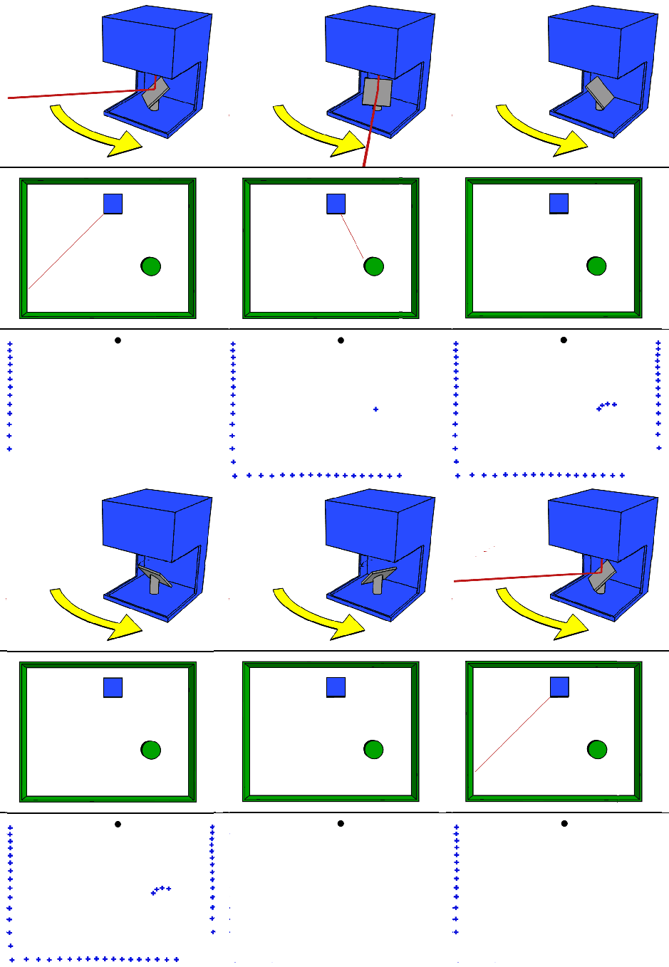
The working principle of the single-wire mechanical rotating radar is as shown in the figure below:
20200512204828561

1.2.1. Trigonometric ranging method

The laser triangulation ranging method mainly uses a beam of laser to illuminate the measured target at a certain incident angle. The laser is reflected and scattered on the target surface. At another angle, a lens is used to converge and image the reflected laser. The spot is imaged on the CCD (Charge-coupled Device, photosensitive coupling component) on the position sensor. When the measured object moves along the direction of the laser, the light spot on the position sensor will move, and its displacement corresponds to the movement distance of the measured object. Therefore, the distance between the measured object and the baseline can be calculated from the light spot displacement distance through algorithm design. value. Since the incident light and the reflected light form a triangle, the geometric triangle theorem is used to calculate the spot displacement, so this measurement method is called the laser triangulation ranging method.

According to the angular relationship between the incident beam and the normal line of the surface of the measured object, the laser triangulation ranging method can be divided into two types: oblique type and direct type.

1. Direct type
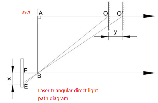
image-20210914120518557

As shown in Figure 1, when the laser beam is vertically incident on the surface of the object to be measured, that is, when the incident light is collinear with the normal line of the surface of the object to be measured, it is a direct laser triangulation method.

2. Oblique shot type

When the angle between the incident laser beam and the normal line of the surface of the object being measured is less than 90° in the optical path system, the incident mode is oblique. The optical path diagram shown in Figure 2 is a laser triangulation oblique optical path diagram.
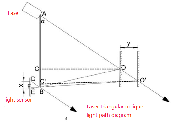
image-20210914120552057

The laser emitted by the laser is incident on the surface of the object being measured at a certain angle with the normal line of the object surface. The reflected (scattered) light is concentrated through the lens at B and is finally collected by the photosensitive unit.

Whether it is the direct or oblique laser triangulation ranging method, it can achieve high-precision, non-contact measurement of the measured object, but the resolution of the direct type is not as high as that of the oblique type.

Silan Technology's RPLIDAR series lidar also uses the oblique laser triangulation ranging method. During each ranging process, the RPLIDAR series lidar will emit a modulated infrared laser signal. The reflection generated by the laser signal after hitting the target object will be received by the RPLIDAR visual acquisition system, and then processed by the DSP embedded inside the RPLIDAR. The device solves the problem in real time, and the distance value between the illuminated target object and the RPLIDAR and the current angle information will be output from the communication interface. Driven by the motor mechanism, the ranging core of RPLIDAR will rotate clockwise, thereby achieving 360-degree all-round scanning and ranging detection of the surrounding environment.

1.2.2. TOF time-of-flight ranging method

TOF lidar is based on measuring the flight time of light to obtain the distance of the target. Its working principle is mainly as follows: a modulated laser signal is emitted through a laser transmitter. The modulated light is received by the laser detector after being reflected by the object being measured. The distance to the target can be calculated by measuring the phase difference between the emitted laser and the received laser. .
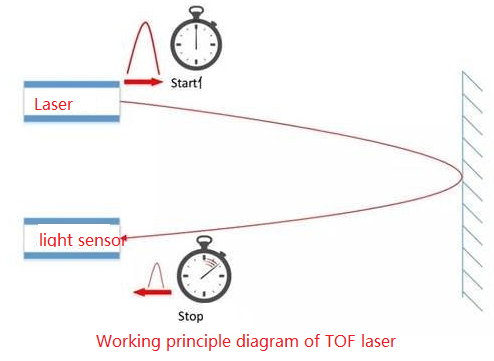
image-20210914120619928

Under the condition of distant objects, its measurement accuracy remains accurate and stable. At the same time, TOF radar is not inferior in its ability to resist light interference due to its ultra-short light pulse characteristics. It can achieve stable ranging and high-precision mapping even under strong light of 60Klx outdoors.

Generally speaking, triangular ranging lidar and TOF lidar have their own difficulties in implementation. In principle, TOF radar has a longer ranging distance. In some occasions where distance is required, TOF radar is the most common, while The manufacturing cost of triangular ranging lidar is relatively low, and its accuracy can meet most industrial-grade civilian requirements, so it has also attracted much attention in the industry.

1.3. Use radar

1.3.1, 4ROS radar:

Terminal run

xxxxxxxxxx
roslaunch ydlidar_ros_driver TG.launch

<PI5 needs to open another terminal to enter the same docker container
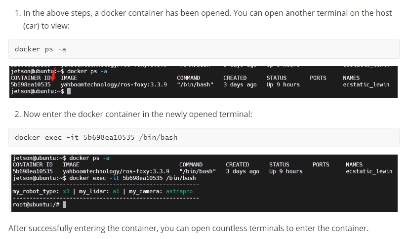
image-20240408144126098

We can print the topic data through the terminal to check whether the radar starts normally, enter the terminal,

xxxxxxxxxx
rostopic echo /scan

If you want to view the scan results in RVIZ, enter in the terminal,

xxxxxxxxxx
roslaunch ydlidar_ros_driver lidar_view.launch
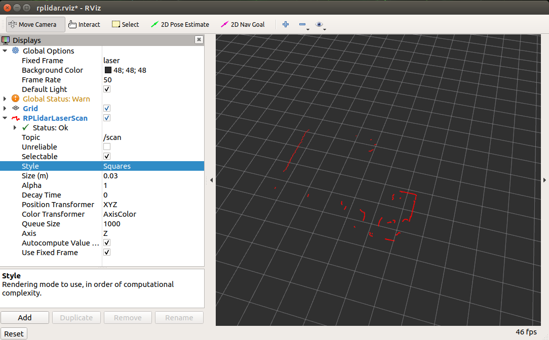
image-20210914120619928

1.3.2, X3/X3Pro radar:

Terminal run

xxxxxxxxxx
roslaunch ydlidar_ros_driver X2.launch

<PI5 needs to open another terminal to enter the same docker container

image-20240408144126098

We can print the topic data through the terminal to check whether the radar starts normally, enter the terminal,

xxxxxxxxxx
rostopic echo /scan

If you want to view the scan results in RVIZ, enter in the terminal,

xxxxxxxxxx
roslaunch ydlidar_ros_driver lidar_view.launch

image-20210914120619928

1.4, launch analysis

Path: ~/software/library_ws/src/ydlidar_ros_driver-master/launch

TG.launch file

xxxxxxxxxx
<launch>
   <arg name="frame_id" default="laser"/>
   <node name="ydlidar_lidar_publisher" pkg="ydlidar_ros_driver" type="ydlidar_ros_driver_node" output="screen" respawn="false" >
     <!-- string property -->
     <param name="port" type="string" value="/dev/ydlidar"/>
     <param name="frame_id" type="string" value="$(arg frame_id)"/>
     <!--param name="ignore_array" type="string" value="-90,90"/-->
     <param name="ignore_array" type="string" value=""/>
     <!--remap from="scan" to="scan_raw"/-->

     <!-- int property -->
     <param name="baudrate" type="int" value="512000"/>
     <!-- 0:TYPE_TOF, 1:TYPE_TRIANGLE, 2:TYPE_TOF_NET -->
     <param name="lidar_type" type="int" value="0"/>
     <!-- 0:YDLIDAR_TYPE_SERIAL, 1:YDLIDAR_TYPE_TCP -->
     <param name="device_type" type="int" value="0"/>
     <param name="sample_rate" type="int" value="20"/>
     <param name="abnormal_check_count" type="int" value="4"/>

     <!-- bool property -->
     <param name="resolution_fixed" type="bool" value="true"/>
     <param name="auto_reconnect" type="bool" value="true"/>
     <param name="reversion" type="bool" value="true"/>
     <param name="inverted" type="bool" value="true"/>
     <param name="isSingleChannel" type="bool" value="false"/>
     <param name="intensity" type="bool" value="false"/>
     <param name="support_motor_dtr" type="bool" value="false"/>
     <param name="invalid_range_is_inf" type="bool" value="true"/>
     <param name="point_cloud_preservative" type="bool" value="false"/>

     <!-- float property -->
     <param name="angle_min" type="double" value="-90" />
     <param name="angle_max" type="double" value="90" />
     <param name="range_min" type="double" value="0.01" />
     <param name="range_max" type="double" value="50.0" />
     <param name="frequency" type="double" value="10.0"/>
   </node>
   <!--node pkg="tf" type="static_transform_publisher" name="base_link_to_laser4"
     args="0.0 0.0 0.2 3.14 0.0 0.0 /base_footprint /laser 40" /-->
</launch>

Main debugging parameters:

  • angle_min parameter: radar left angle

  • angle_max parameter: radar right angle

For other parameters, please refer to the official documentation.

ydlidar_ros_driver/README.md at master · YDLIDAR/ydlidar_ros_driver· GitHub

Lidar basic-SLAM
Lidar avoiding

COMPANY

  • About us
  • Team Style
  • Blog

LEARNING & EXPLORATION

  • Tutorials
  • Edge AI hardware
  • Educational robots
  • Embedded intelligent hardware

WHERE TO BUY

  • Yahboom Online Store
  • Amazon
  • Alibaba
  • AliExpress
  • Mercado

TECHNOLOGY SUPPORT

  • Email: support@yahboom.com

BE A DISTRIBUTOR

  • Email: sales@yahboom.com
QR Code
QR Code

Copyright © 2017-2026 Yahboom. All Rights Reserved.

EN/中文