Welcome to ROSMASTER X3 Plus repository
12.Navigation and avoiding
12. Navigation and avoiding
12. Navigation and avoiding12.1 Operation and use 12.1.1 Start 12.1.2 Use 12.1.3 Dynamic parameter adjustment 12.1.4 Node graph 12.1.5 tf coordinate system 12.2 navigation 12.2.1 Introduction 12.2.2 set tf 12.3 move_base 12.3.1 Introduction 12.3.2 move_base communication mechanism 1) Action 2) topic 3) tableware 4) Parameter configuration 12.3.3 Recovery Behavior 1 Introduction 2) Related function packages 12.4 costmap_params 12.4.1 costmap_common 12.4.2 global_costmap 12.4.3 local_costmap 12.4.4 costmap_2D 1 Introduction 2)topic 3) Parameter configuration 4) Layer Specifications 5)obstacle layer 6) Inflation layer 12.5 planner_params 12.5.1 global_planner 12.5.2 local_planner 1)dwa_local_planner 2)teb_local_planner
navigation: http://wiki.ros.org/navigation/
navigation/Tutorials: http://wiki.ros.org/navigation/Tutorials/RobotSetup
costmap_2d: http://wiki.ros.org/costmap_2d
nav_core: http://wiki.ros.org/nav_core
global_planner: http://wiki.ros.org/global_planner
dwa_local_planner: http://wiki.ros.org/dwa_local_planner
teb_local_planner: http://wiki.ros.org/teb_local_planner
move_base: http://wiki.ros.org/move_base
12.1 Operation and use
Note: [R2] of the remote control handle has the function of canceling the target point.
According to different models, you only need to set the purchased model in [.bashrc], X1(ordinary four-wheel drive) X3(Mike wheel) X3plus(Mike wheel mechanical arm) R2(Ackerman differential) and so on, to X3 as an example
Open the [.bashrc] file
sudo vim .bashrc Find the [ROBOT_TYPE] parameter and modify the corresponding model
xxxxxxxxxxexport ROBOT_TYPE=X3 # ROBOT_TYPE: X1 X3 X3plus R2 X7 12.1.1 Start
Start the driver(robot side), for the convenience of operation, this section takes [mono + laser + yahboomcar] as an example.
x#You need to enter docker first, perform this step more#If running the script to enter docker fails, please refer to 07.Docker-orin/05, Enter the robot's docker container~/run_docker.shroslaunch yahboomcar_nav laser_bringup.launch # laser + yahboomcar roslaunch yahboomcar_nav laser_usb_bringup.launch # mono + laser + yahboomcar roslaunch yahboomcar_nav laser_astrapro_bringup.launch # Astra + laser + yahboomcar Start the navigation obstacle avoidance function(robot side), you can set parameters and modify the launch file according to your needs.
<Open another terminal and enter the same docker container
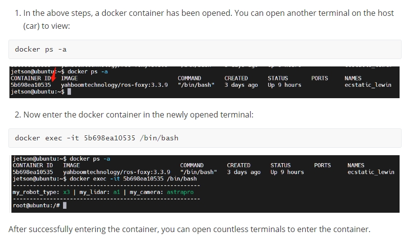
xxxxxxxxxxroslaunch yahboomcar_nav yahboomcar_navigation.launch use_rviz:=false map:=house - [use_rviz] parameter: whether to open rviz.
- [map] Parameters: map name, the map to be loaded.
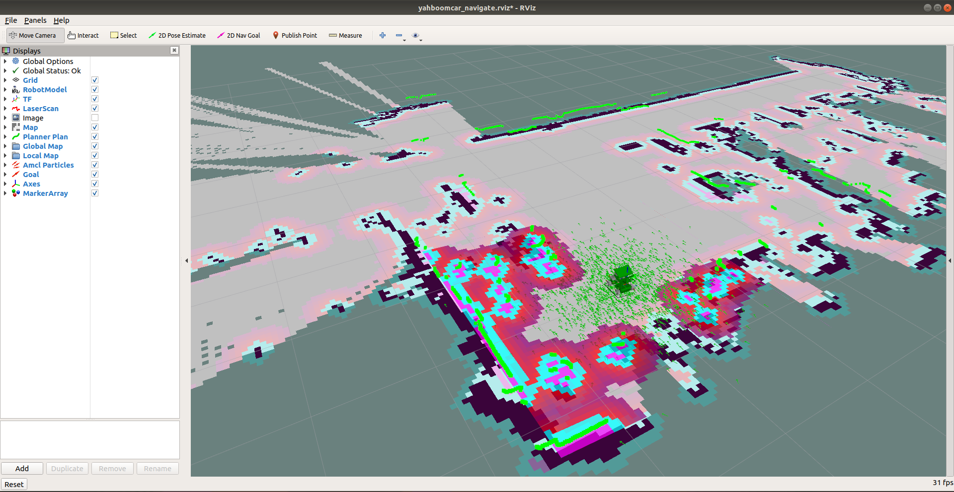
Open the visual interface(virtual machine side)
xxxxxxxxxxroslaunch yahboomcar_nav view_navigate.launch
12.1.2 Use
1) Single point navigation
- Use the [2D Pose Estimate] of the [rviz] tool to set the initial pose until the position of the car in the simulation is consistent with the position of the actual car.
- Click the [2D Nav Goal] of the [rviz] tool, and then select the target point on the map where there are no obstacles, release the mouse to start the navigation, only one target point can be selected, and it will stop when it arrives.
2) Multi-point navigation
- Same as the first step of single-point navigation, first set the initial pose of the car.
- Click the [Publish Point] of the [rviz] tool, and then select the target point on the map where there are no obstacles, release the mouse to start the navigation, you can click the [Publish Point] again, and then select the point, the robot will point and point cruising in between.
- When using the [2D Pose Estimate] tool of the [rviz] tool to set the initial pose of the car, the multi-point navigation function is automatically canceled.
3) Parameter configuration
According to different models, you only need to set the purchased model in [.bashrc], X1(ordinary four-wheel drive) X3(Mike wheel) X3plus(Mike wheel mechanical arm) R2(Ackerman differential) and so on, to X3 as an example
Open the [.bashrc] file
xxxxxxxxxxsudo vim .bashrc Find the [ROBOT_TYPE] parameter and modify the corresponding model
xxxxxxxxxxexport ROBOT_TYPE=X3 # ROBOT_TYPE: X1 X3 X3plus R2 X7 Looking at the yahboomcar_navigation.launch file, you can see that the navigation parameters are modified in the move_base.launch file under the yahboomcar_nav function package.
xxxxxxxxxx< launch > <!-- Whether to open rviz || Whether to open rviz --> < arg name = "use_rviz" default = "true" /> <!-- map name|| Map name my_map--> < arg name = "map" default = "my_map" /> <!-- MarkerArray node> --> < node name = 'send_mark' pkg = "yahboomcar_nav" type = "send_mark.py" /> <!-- Load map || Load map --> < node name = "map_server" pkg = "map_server" type = "map_server" args = "$(find yahboomcar_nav)/maps/$(arg map).yaml" /> <!-- AMCL Adaptive Monte Carlo Positioning--> < include file = "$(find yahboomcar_nav)/launch/library/amcl.launch" /> <!-- Mobile APP Node--> < include file = "$(find yahboomcar_nav)/launch/library/app.launch" /> <!-- Navigation core component move_base --> < include file = "$(find yahboomcar_nav)/launch/library/move_base.launch" /> <!-- RVIZ --> < include file = "$(find yahboomcar_nav)/launch/view/view_navigate.launch" if = "$(arg use_rviz)" /> </ launch > Find the move_base.launch file, open the sample file as follows, you can modify and replace it according to your needs; at this time, the [DWA planner] is selected, and the [DWA] file is loaded.
xxxxxxxxxx< launch >< arg name = "robot_type" value = "$(env ROBOT_TYPE)" doc = "robot_type [X1,X3,X3plus,R2,X7]" /><!-- Arguments -->< arg name = "move_forward_only" default = "false" /><!-- move_base -->< node pkg = "move_base" type = "move_base" respawn = "false" name = "move_base" output = "screen" >< rosparam file = "$(find yahboomcar_nav)/param/common/global_costmap_params.yaml" command = "load" />< rosparam file = "$(find yahboomcar_nav)/param/common/local_costmap_params.yaml" command = "load" />< rosparam file = "$(find yahboomcar_nav)/param/common/move_base_params.yaml" command = "load" />< rosparam file = "$(find yahboomcar_nav)/param/common/costmap_common_params_$(arg robot_type).yaml" command = "load"ns = "global_costmap" />< rosparam file = "$(find yahboomcar_nav)/param/common/costmap_common_params_$(arg robot_type).yaml" command = "load"ns = "local_costmap" />< rosparam file = "$(find yahboomcar_nav)/param/common/dwa_local_planner_params_$(arg robot_type).yaml" command = "load" />< param name = "base_local_planner" type = "string" value = "dwa_local_planner/DWAPlannerROS" if = "$(eval arg('robot_type') == 'X3')" /><!-- <param name="base_local_planner" type="string" value="teb_local_planner/TebLocalPlannerROS"/>-->< param name = "DWAPlannerROS/min_vel_x" value = "0.0" if = "$(arg move_forward_only)" />< remap from = "cmd_vel" to = "cmd_vel" />< remap from = "odom" to = "odom" /></ node ></ launch >
Note: When using the DWA planner, the difference between the omnidirectional car and the differential car is whether the speed in the Y direction is 0. There are clear comments in it, which can be modified according to the actual situation.
Enter the dwa_local_planner_params.yaml file under the yahboomcar_nav function package, some parameters are as follows:
xxxxxxxxxxDWAPlannerROS :# Robot Configuration Parameters# The absolute value of the maximum linear velocity in the x direction, unit: m/s# The maximum y velocity for the robot in m/smax_vel_x : 0.6# The absolute value of the minimum linear velocity in the x direction, a negative number means that it can be moved back, unit: m/s# The minimum x velocity for the robot in m/s, negative for backwards motion.min_vel_x : - 0.6# The absolute value of the maximum linear velocity in the y direction, unit: m/s. Differential robot is 0# The maximum y velocity for the robot in m/smax_vel_y : 0.3# The absolute value of the minimum linear velocity in the y direction, unit: m/s. Differential robot is 0# The minimum y velocity for the robot in m/smin_vel_y : - 0.3…# The limit acceleration of the robot in the x direction, the unit is meters/sec^2# The x acceleration limit of the robot in meters/sec^2acc_lim_x : 10.0# The limit acceleration of the robot in the y direction, it is 0 for the differential robot# The y acceleration limit of the robot in meters/sec^2acc_lim_y : 10.0... ..
Other parameter files can be opened, combined with annotations and courseware, and modified according to their own needs.
12.1.3 Dynamic parameter adjustment
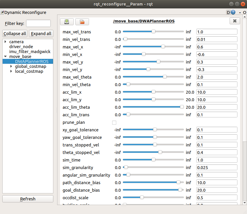
After starting the navigation function, open the dynamic parameter adjustment tool, adjust it according to your own needs, and observe the motion state of the robot until the effect is optimal, record the current parameters, and modify them to the dwa_local_planner_params.yaml file under the yahboomcar_nav function package.
xxxxxxxxxxrosrun rqt_reconfigure rqt_reconfigure
12.1.4 Node graph
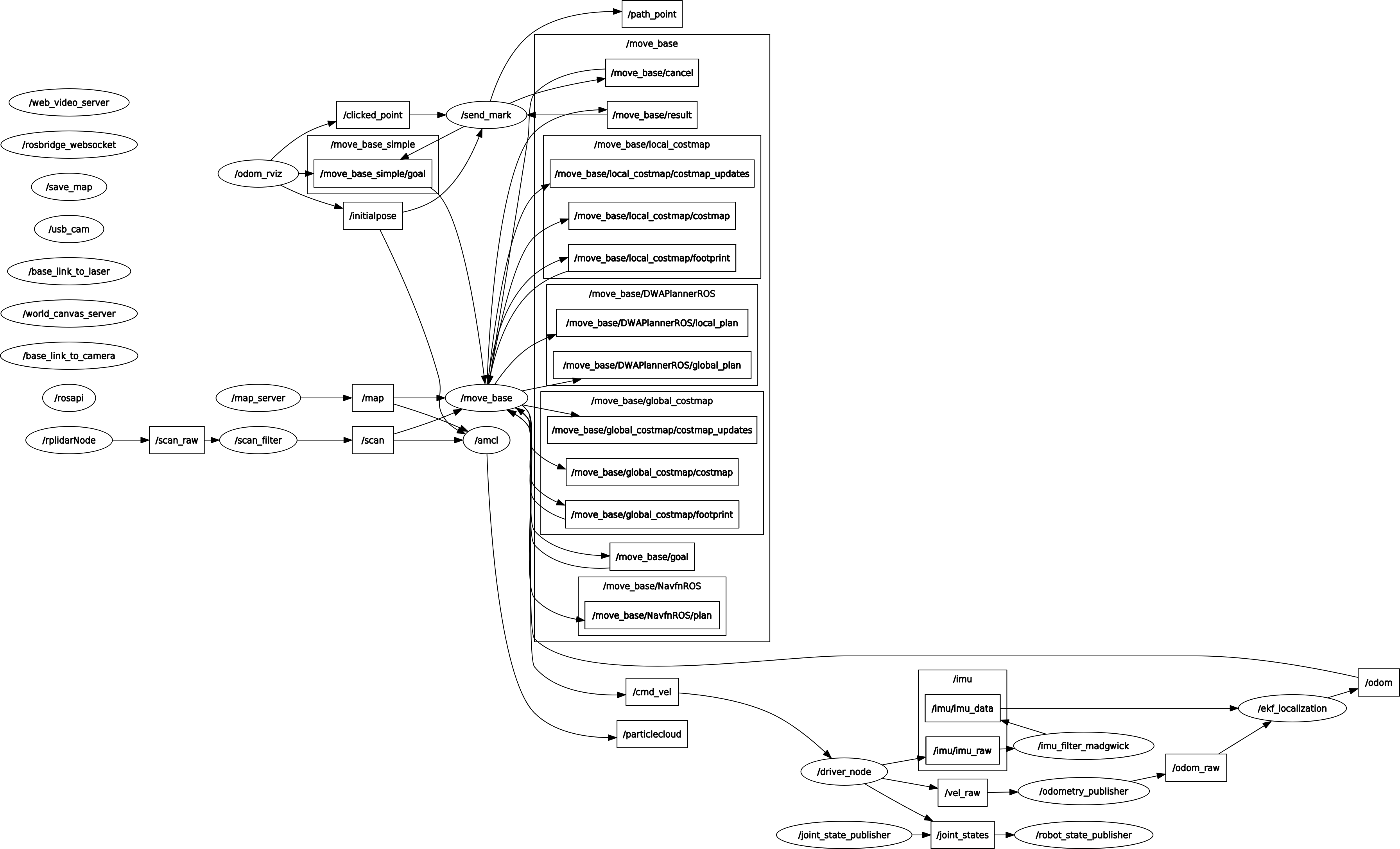
Take [mono + laser + yahboomcar] started in section [1.1] as an example to observe the communication between nodes.
xxxxxxxxxxrosrun rqt_graph rqt_graph
12.1.5 tf coordinate system
The transformation relationship between coordinates.
xxxxxxxxxxrosrun rqt_tf_tree rqt_tf_tree

12.2 navigation
12.2.1 Introduction
Navigation is a two-dimensional navigation obstacle avoidance function package of ROS. In simple terms, it is based on the information flow of the input odometer and other sensors and the global position of the robot, through the navigation algorithm, calculates the safe and reliable robot speed control command.
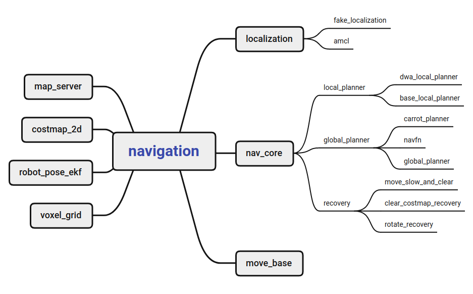
navigation main nodes and configuration
- move_base: The final actuator of navigation obstacle avoidance control, move_base subscribes to the navigation target move_base_simple/goal, and publishes the motion control signal cmd_vel in real time. Various navigation algorithm modules in move_base are called in the form of plug-ins.
- global_planner: used for global path planning.
- local_planner: used for local path planning.
- global_costmap: The global costmap is used to describe the global environment information.
- local_costmap: The local costmap is used to describe local environment information.
- recovery_behaviors: The recovery strategy is used for automatic escape recovery after the robot encounters obstacles.
- amcl: The particle filter algorithm is used to realize the global positioning of the robot and provide global position information for the robot navigation.
- map_server: Maps obtained by calling SLAM to provide environmental map information for navigation.
- costmap_2d: Can produce costmaps and provide various related functions.
- robot_pose_ekf: Extended Kalman filter, the input is any two or three of the odometer, IMU, and VO, and the output is a fused pose.
- fake_localization: Generally used for simulation.
- nav_core: There are only three files in it, which correspond to the general interface definitions of global path planning, local path planning, and recovery_action. The specific function implementation is in each corresponding planner function package.
- It is also necessary to provide tf information, odometer odom information, and lidar scan information related to the robot model.
12.2.2 set tf
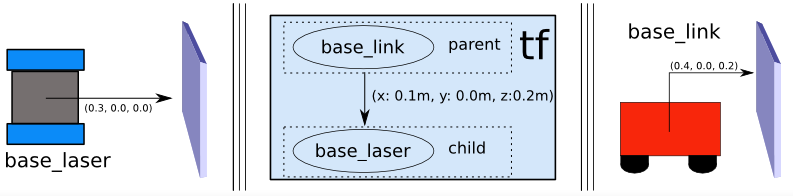
The navigation function requires the robot to publish information about the relationship between the coordinate systems using tf. Example: Lidar
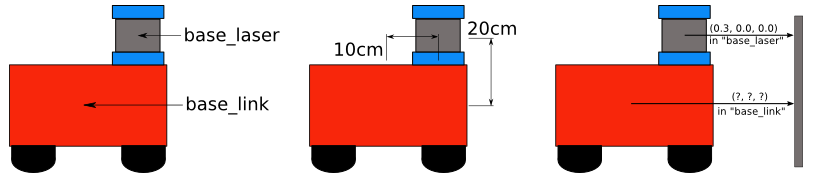
Suppose we know that the lidar is mounted 10 cm and 20 cm above the center point of the mobile base. This gives us the translation offset to associate the "base_link" frame with the "base_laser" frame. Specifically, we know that to get data from the "base_link" coordinate system to the "base_laser" coordinate system, we have to apply a translation of(x: 0.1m, y: 0.0m, z: 0.2m) and get the data from the "base_laser" frame To the "base_link" frame, we have to apply the opposite translation(x: -0.1m, y: 0.0m, z: -0.20m).
12.3 move_base
12.3.1 Introduction
move_base provides the configuration, operation and interaction interface of ROS navigation.
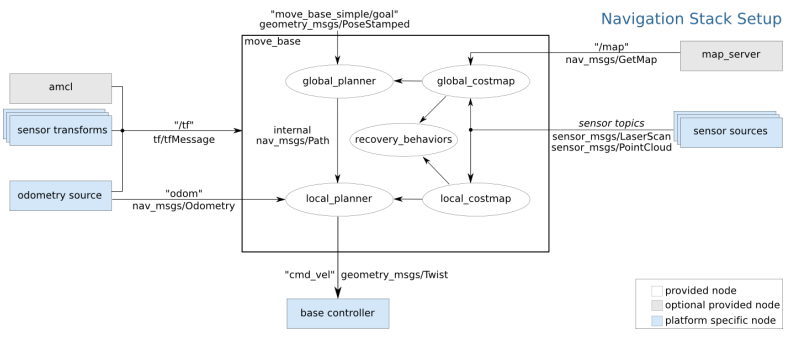
Implementing the robot navigation function must be configured in a specific way, as shown above:
- White components are required components that have been implemented,
- Grey components are optional components that have been implemented,
- Blue components must be created for each robot platform.
12.3.2 move_base communication mechanism
1) Action
The move_base node provides an implementation of SimpleActionServer that receives targets containing geometry_msgs/PoseStamped messages. You can communicate directly with the move_base node via ROS, but if you care about tracking the state of the target, it is recommended to use SimpleActionClient to send the target to the move_base.(See actionlib documentation )
| name | type | illustrate |
|---|---|---|
| move_base/goal | move_base_msgs/MoveBaseActionGoal | move_base subscribes to the target point to be reached. |
| move_base/cancel | actionlib_msgs/GoalID | move_base subscribes to cancel requests for a specific target. |
| move_base/feedback | move_base_msgs/MoveBaseActionFeedback | The post contains the current position of the chassis. |
| move_base/status | actionlib_msgs/GoalStatusArray | Publishes status information for the move to the target point process. |
| move_base/result | move_base_msgs/MoveBaseActionResult | Post the final result of the move. |
2) topic
| name | type | illustrate |
|---|---|---|
| move_base_simple/goal | geometry_msgs/PoseStamped | Provides a non-action interface that does not care about the execution state of the tracking target. move_base subscribes to the target point to be reached. |
| cmd_vel | geometry_msgs/Twist | Publishes the speed of the car's movement. |
3) tableware
| name | type | illustrate |
|---|---|---|
| make_plan | nav_msgs/GetPlan | Allows external users to request a plan for a given pose from move_base without causing move_base to execute the plan. |
| clear_unknown_space | std_srvs/Empty | Allows external users to notify move_base to clear unknown spaces in the area around the robot. This is useful when move_base's costmaps are stopped for a long period of time and then restarted at a new location in the environment. |
| clear_costmaps | std_srvs/Empty | Allows external users to tell move_base to clear barriers in the costmap used by move_base. This may cause the robot to bump into things and should be used with caution |
4) Parameter configuration
move_base_params.yaml
xxxxxxxxxx# Set the plugin name of the global path planner for move_base #base_global_planner: "navfn/NavfnROS" base_global_planner "global_planner/GlobalPlanner" #base_global_planner: "carrot_planner/CarrotPlanner" # Set the plugin name of the local path planner for move_base #base_local_planner: "teb_local_planner/TebLocalPlannerROS" # Implement an online optimized local trajectory planner base_local_planner "dwa_local_planner/DWAPlannerROS" # Implement DWA(dynamic window method) local planning algorithm # Restore behavior. recovery_behaviors name 'conservative_reset' type 'clear_costmap_recovery/ClearCostmapRecovery' #- name: 'aggressive_reset' # type: 'clear_costmap_recovery/ClearCostmapRecovery' #- name: 'super_reset' # type: 'clear_costmap_recovery/ClearCostmapRecovery' name 'clearing_rotation' type 'rotate_recovery/RotateRecovery' #- name: 'move_slow_and_clear' #type: 'move_slow_and_clear/MoveSlowAndClear' # How often to send commands to the robot chassis cmd_vel controller_frequency 10.0 # The time the path planner waits for a valid control command before the space cleanup operation is executed planner_patience 5.0 # The time the controller waits for a valid control command before the space cleaning operation is executed controller_patience 15.0 # This parameter is only used when the default restore behavior is used for move_base. conservative_reset_dist 3.0 # Whether to enable the move_base restore behavior to try to clear space. recovery_behavior_enabled true # Whether the robot uses in-situ rotation to clear the space, this parameter is only used when the default recovery behavior is used. clearing_rotation_allowed true # When move_base enters the inactive state, whether to disable the costmap of the node shutdown_costmaps false # The time allowed to oscillate before performing the recovery operation, 0 means never timeout oscillation_timeout 10.0 # The robot needs to move this distance to be considered as having no vibration. Reset timer parameters after moving oscillation_distance 0.2 # Global path planner cycle rate. planner_frequency 5.0 # The number of times to allow scheduled retries before performing recovery behavior. A value of -1.0 corresponds to infinite retries. max_planning_retries -1.0 12.3.3 Recovery Behavior
1 Introduction
When ① the global planning fails, ② the robot oscillates, and ③ the local planning fails, it will enter the recovery behavior. These recovery behaviors can be configured with the recovery_behaviour parameter and disabled with the recovery_behavior_enabled parameter.
Desired Robot Behavior
First, obstacles outside the user-specified area are cleared from the robot's map. Next, if possible, the robot will perform a spin in place to clear the space. If this also fails, the robot will more aggressively clear the map, clearing all obstacles outside the rectangular area where the robot can rotate in place. Another in-place spin will follow. If all of these fail, the bot considers its goal unfeasible and informs the user that it has aborted.
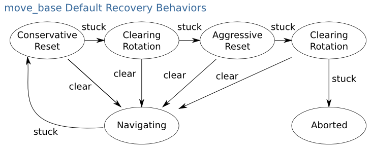
- conservative reset: conservative recovery.
- clearing rotation: Rotation clearing.
- aggressive reset: Aggressive recovery.
- aborted: aborted.
2) Related function packages
In the set of navigation function packs, there are 3 packs related to the recovery mechanism. They are: clear_costmap_recovery, move_slow_and_clear, rotate_recovery. Three classes are defined in these three packages, all of which inherit the interface specification in nav_core.
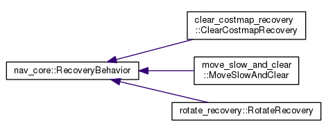
- move_slow_and_clear : is a simple recovery behavior that clears the information in the costmap and then limits the speed of the robot. Note that this recovery behavior is not really safe, the robot may hit the object, it will only happen at the speed specified by the user.
| parameter | type | Defaults | Parse |
|---|---|---|---|
| clearing_distance | double | 0.5 | Obstacles within the robot's clearing distance will be cleared(unit: m). |
| limited_trans_speed | double | 0.25 | When performing this recovery behavior, the robot's translation speed will be limited(unit: m/s). |
| limited_rot_speed | double | 0.25 | When this recovery behavior is performed, the rotational speed of the robot will be limited(unit: rad/s). |
| limited_distance | double | 0.3 | The distance(unit: m) that the robot must move before releasing the speed limit. |
| planner_namespace | string | "DWAPlannerROS" | The name of the planner whose parameters are to be reconfigured. |
- rotate_recovery : Rotation recovery, clearing space by rotating the robot 360 degrees.
| parameter | type | Defaults | Parse |
|---|---|---|---|
| sim_granularity | double | 0.017 | When checking whether it is safe to rotate in place, the distance between checking obstacles is 1 degree by default(unit: rad). |
| frequency | double | 20.0 | The frequency(unit: Hz) of sending speed commands to the mobile robot. |
| TrajectoryPlannerROS/yaw_goal_tolerance | double | 0.05 | The tolerance in radians for the controller in yaw/rotation to achieve its goal. |
| TrajectoryPlannerROS/acc_lim_th | double | 3.2 | The rotational acceleration limit of the robot(unit: rad/s^2). |
| TrajectoryPlannerROS/max_rotational_vel | double | 1.0 | The maximum rotation speed allowed by the base(unit: rad/s). |
| TrajectoryPlannerROS/min_in_place_rotational_vel | double | 0.4 | The minimum rotation speed(unit: rad/s) allowed by the base when performing an in-position rotation. |
Note: The TrajectoryPlannerROS parameter is only set when using the base_local_planner::TrajectoryPlannerROS planner; generally it is not required.
- clear_costmap_recovery : A recovery behavior that restores the costmap used by move_base to a static map outside the user-specified range.
| parameter | type | Defaults | Parse |
|---|---|---|---|
| clearing_distance | double | 0.5 | The length centered on the robot that the obstacle will be removed from the costmap when it reverts to a static map. |
12.4 costmap_params
The navigation function uses two costmaps to store information about obstacles. One costmap is used for global planning, which means creating global planning routes across the entire environment, and the other is used for local planning and obstacle avoidance. The two costmaps have some common configuration and some individual configuration. Therefore, the costmap configuration has the following three parts: general configuration, global configuration and local configuration.
12.4.1 costmap_common
Costmap public parameter configuration costmap_common_params.yaml
xxxxxxxxxxobstacle_range 2.5 raytrace_range 3.0 footprint x0 y0 x1 y1 ... xn at # robot_radius: ir_of_robot inflation_radius 0.55 observation_sources laser_scan_sensor laser_scan_sensor sensor_frame frame_name data_type LaserScan topic topic_name marking true clearing true parameter parsing
obstacle_range: The default value is 2.5 meters, which means that the robot will only update information about obstacles within a range of 2.5 meters.
raytrace_range: The default value is 3.0 meters, which means the robot will try to clear space beyond 3.0 meters in front of it.
Footprint: Set the occupied area of the robot. When filling in the footprint specified by "footprint" according to the robot coordinate setting, the center of the robot is considered to be at(0.0, 0.0), both clockwise and counterclockwise can be set.
robot_radius: The occupied area of the robot is a circle, and the radius can be set directly. Not shared with footprint.
inflation_radius: Set the costmap inflation radius. Default 0.55. It means that the robot will consider the obstacle within 0.55 meters of the obstacle.
observation_sources: defines a list of sensors that pass information to a space-separated costmap.
laser_scan_sensor: defines each sensor.
- sensor_frame: The name of the sensor coordinate system.
- data_type: The parameter is set to LaserScan or PointCloud, depending on the message used by the topic.
- topic: The topic name of the sensor to publish data.
- marking: Whether to add obstacle information to the costmap.
- clearing: Whether to clear the obstacle information in the costmap.
12.4.2 global_costmap
Global costmap parameter configuration global_costmap_params.yaml
xxxxxxxxxxglobal_costmap global_frame map robot_base_frame base_link update_frequency 5.0 static_map true - global_frame: The coordinate system in which the global costmap runs.
- robot_base_frame: The robot base coordinate system referenced by the global costmap.
- update_frequency: The frequency at which the global costmap is cyclically updated, in Hz.
- static_map: Whether the global costmap should be initialized based on the map provided by map_server. If you are not using an existing map or map server, set the static_map parameter to false.
12.4.3 local_costmap
Local costmap parameter configuration local_costmap_params.yaml
xxxxxxxxxxlocal_costmap global_frame odom robot_base_frame base_link update_frequency 5.0 publish_frequency 2.0 static_map false rolling_window true width 6.0 height 6.0 resolution 0.05 parameter parsing
- global_frame: The coordinate frame in which the local costmap operates.
- robot_base_frame: The robot base coordinate frame referenced by the local costmap.
- update_frequency: The frequency at which the local costmap is cyclically updated, in Hz.
- publish_frequency: The rate at which the local costmap publishes visualization information, in Hz.
- static_map: Whether the local costmap should be initialized based on the map provided by map_server. If you are not using an existing map or map server, set the static_map parameter to false.
- rolling_window:(rolling window) parameter set to true means that when the robot is moving, the local costmap will remain centered on the robot.
- width: local costmap width(meters).
- height: Local costmap height(meters).
- resolution: Local costmap resolution(meters/unit).
12.4.4 costmap_2D
1 Introduction
The costmap_2d package provides a 2D costmap implementation that takes input sensor data, builds a 2D or 3D costmap of the data(depending on whether a voxel-based implementation is used), and uses occupancy grids and user-defined inflation Radius computes the cost of the 2D costmap.
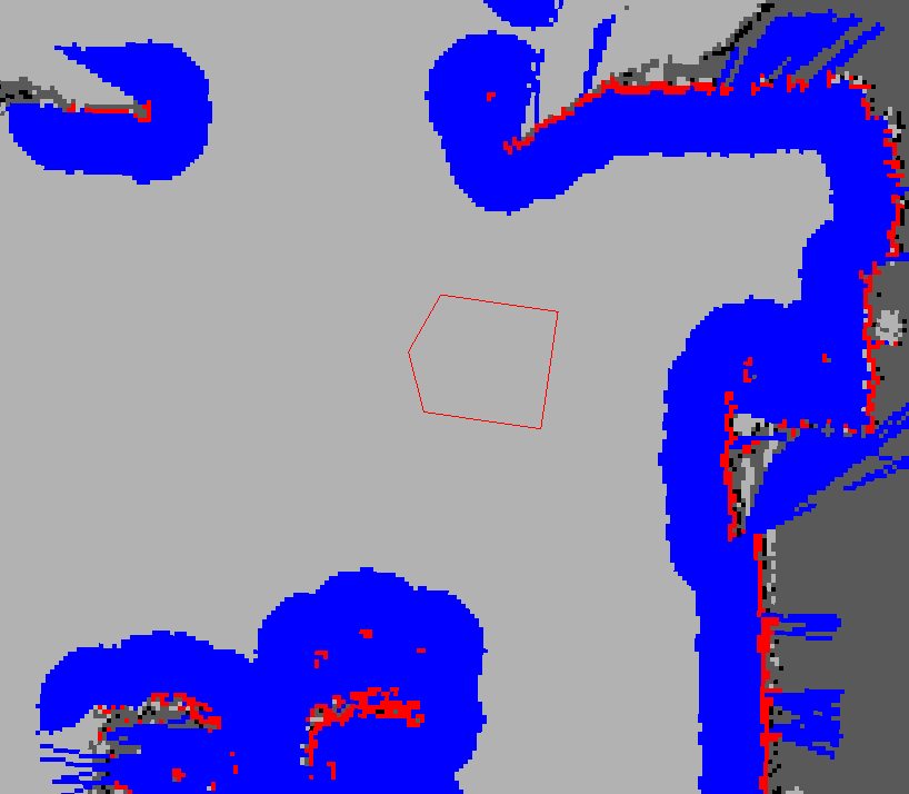
- Red represents obstacles in the costmap.
- Blue represents obstacles with expanded radius inscribed in the robot,
- The red polygons represent the robot's footprint.
- In order for the robot to avoid collisions, the robot's shell must never intersect the red cells, and the robot's center point must never intersect the blue cells.
2)topic
| name | type | illustrate |
|---|---|---|
| footprint | geometry_msgs/Polygon | Robot enclosure specification. This replaces the previous parameter specification for the package outline. |
| costmap | nav_msgs/OccupancyGrid | cost map |
| costmap_updates | map_msgs/OccupancyGridUpdate | Update area of the costmap |
| voxel_grid | costmap_2d/VoxelGrid | voxel grid |
3) Parameter configuration
If you don't provide the plugins parameter, the initialization code will assume your configuration is pre-Hydro, and the default namespaces are static_layer, obstacle_layer, and inflation_layer.
plugin
- plugins: generally use the default.
Coordinate system and tf parameters
- global_frame: The global coordinate system in which the costmap runs.
- robot_base_frame: The coordinate system name of the robot base_link.
- transform_tolerance: Specifies the tolerable transform(tf) data delay(unit: s).
Rate parameter
- update_frequency: Frequency of updating the map(unit: Hz).
- publish_frequency: The frequency(unit: Hz) of publishing the map showing the information.
Map management parameters
- rolling_window: Whether to use the rolling window version of the costmap. If the static_map parameter is set to true, this parameter must be set to false.
- always_send_full_costmap: If true, the full costmap will be published to "/costmap" on every update. If false, only the changed costmap parts will be published on the "/costmap_updates" topic.
static layer
- width: The width of the map(unit: m).
- height: The height of the map(unit: m).
- resolution: map resolution(unit: m/cell).
- origin_x: The x origin of the map in the global frame(unit: m).
- origin_y: The y origin of the map in the global frame(unit: m).
tf transform
global_fram——>robot_base_frame
4) Layer Specifications
Static layer static map layer : The static layer is basically unchanged in the cost map.
Subscribe to topics
- map: The costmap will make a service call to map_server to get this map.
parameter
- unknown_cost_value: This value is read from the map provided by the map server, and its cost will be treated as unknown. A value of zero also causes this parameter to be unused.
- lethal_cost_threshold: Consider the lethal threshold when reading maps from the map server.
- map_topic: Specifies the topic that the costmap uses to subscribe to the static map.
- first_map_only: Only subscribe to the first message on the map topic, ignoring all subsequent messages.
- subscribe_to_updates: In addition to map_topic, also subscribe to map_topic + "_updates".
- track_unknown_space: If true, unknown values in map messages will be converted directly to the layer. Otherwise, unknown values in the map message are converted to free space in the layer.
- use_maximum: Only matters if the static layer is not the bottom layer. If true, only the maximum value will be written to the main costmap.
- trinary_costmap: If true, convert all map message values to NO_INFORMATION/FREE_SPACE/LETHAL_OBSTACLE(three values). If false, the full range of intermediate values may appear.
Obstacle layer : The obstacle layer tracks the obstacles read by the sensor data. The collision costmap plugin labels and raytraces obstacles in 2D, while the VoxelCostmapPlugin labels and raytraces obstacles in 3D.
Inflation layer : Add new values around lethal obstacles(i.e. inflate obstacles) so that the costmap represents the robot's configuration space.
Other layers: Other layers can be implemented and used in the costmap through pluginlib .
5)obstacle layer
Obstacle layers and voxel layers contain information from sensors in the form of point clouds or laser scans. Barrier layers track in 2D, while voxel layers track in 3D.
The costmap is automatically subscribed to the sensor topic and updated accordingly. Each sensor is used for marking(inserting obstacle information into the costmap), clearing(removing obstacle information from the costmap). Each time the data is observed, the clear operation performs ray tracing through the mesh from the sensor origin outwards. In the voxel layer, the obstacle information in each column is down-projected into a 2D map.
Subscribe to topics
| topic name | type | Parse |
|---|---|---|
| point_cloud_topic | sensor_msgs/PointCloud | Update PointCloud information to costmap. |
| point_cloud2_topic | sensor_msgs/PointCloud2 | Update PointCloud2 information to costmap |
| laser_scan_topic | sensor_msgs/LaserScan | Update LaserScan information to costmap |
| map | nav_msgs/OccupancyGrid | The costmap has the option to initialize from a user-generated static map |
Sensor Management Parameters
observation_sources: list of observation source names
Each source name in an observation source defines a namespace where parameters can be set:
- <source_name>/topic: The topic covered by the sensor data.
- <source_name>/sensor_frame: Sensor. Can be sensor_msgs/LaserScan, sensor_msgs/PointCloud, and sensor_msgs/PointCloud2.
- <source_name>/observation_persistence: The time(unit: s) to hold each sensor reading. A value of 0.0 will keep only the most recent reading.
- <source_name>/expected_update_rate: Frequency of sensor readings(unit: s). A value of 0.0 will allow infinite time between readings.
- <source_name>/data_type: The data type associated with the topic, currently only "PointCloud", "PointCloud2" and "LaserScan" are supported.
- <source_name>/clearing: Whether this observation should be used to clear free space.
- <source_name>/marking: Whether this observation should be used to mark obstacles.
- <source_name>/max_obstacle_height: The maximum height(unit: m) of sensor readings that are considered valid. This is usually set slightly above the height of the robot.
- <source_name>/min_obstacle_height: Minimum height(unit: m) for sensor readings to be considered valid. This is usually set to ground level, but can be set higher or lower depending on the noise model of the sensor.
- <source_name>/obstacle_range: Maximum range(unit: m) to insert obstacles into the costmap using sensor data.
- <source_name>/raytrace_range: Maximum range(unit: m) to raytrace obstacles from the map using sensor data.
- <source_name>/inf_is_valid: Allows the entry of Inf values in "Laser Scan" observations. Conversion of Inf values to laser maximum range
Global filter parameters: These parameters apply to all sensors.
- max_obstacle_height: The maximum height(unit: m) of any obstacle to insert into the costmap. This parameter should be set slightly above the height of the robot.
- obstacle_range: The default maximum distance from the robot when inserting obstacles into the costmap(unit: m). This can be overkill on a per-sensor basis.
- raytrace_range: The default range(unit: m) to raytrace obstacles from the map using sensor data. This can be overkill on a per-sensor basis.
ObstacleCostmapPlugin
- track_unknown_space: If false, each pixel has one of two states: fatally obstructed or free. If true, each pixel has one of three states: fatally impeded, free, or unknown.
- footprint_clearing_enabled: If true, the robot footprint will clear(mark as free) the space it moves.
- combination_method: Changes how the barrier layer handles incoming data from layers outside it. Possible values are "override"(0), "max"(1), and "none"(99).
VoxelCostmapPlugin
- origin_z: The z origin of the map(unit: m).
- z_resolution: The z resolution of the map(unit: m/cell).
- z_voxels: number of voxels in each vertical column, grid height is z_resolution * z_voxels
- unknown_threshold: The number of unknown cells in the column that are considered "known"
- mark_threshold: The maximum number of marked cells allowed in a column that is considered "free".
- publish_voxel_map: Whether to publish the base voxel raster for visualization purposes.
- footprint_clearing_enabled: If true, the robot footprint will clear(mark as free) the space it moves.
6) Inflation layer
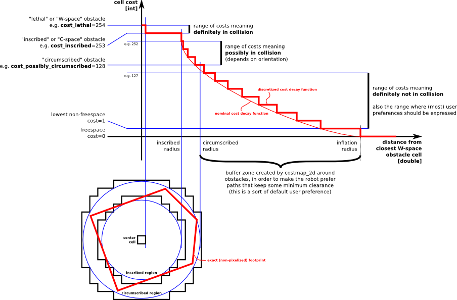
The inflation cost decreases as the robot's distance from the obstacle increases. Define 5 specific symbols related to bots for the cost value of the costmap.
- Fatal("Lethal" cost): Indicates that there is a real obstacle in the cell. If the center of the robot is in this cell, the robot will inevitably collide with the obstacle.
- Inscribed("Inscribed" cost): Indicates that the distance between the cell and the obstacle is less than the radius of the inscribed circle of the robot. If the center of the robot is at or above the "Inscribed" cost cell, the robot is bound to collide with the obstacle.
- Possibly circumscribed("Possibly circumscribed" cost): Indicates that the distance of a cell from the obstacle is less than the radius of the circumscribed circle of the robot, but greater than the radius of the circumscribed circle. If the center of the robot is in a cell equal to or higher than the "Possibly circumscribed" cost, the machine will not necessarily collide with the obstacle, depending on the orientation of the robot.
- Freespace("Freespace"): Nothing prevents the robot from going there.
- Unknown("Unknown"): Unknown space.
parameter
- inflation_radius: The radius(unit: m) to which the map will inflate the obstacle cost value.
- cost_scaling_factor: Scaling factor applied to cost values during inflation.
12.5 planner_params
12.5.1 global_planner
nav_core::BaseGlobalPlanner provides an interface for the global planner used in navigation. All global planners written as move_base node plugins must adhere to this interface. Documentation on NavaCys::BaseGoLBalPrimeNe:C++ documentation can be found here: BaseGlobalPlanner documentation .
Global Path Planning Plugin
- navfn : A grid map-based global planner that calculates the robot's path when using the navigation function. Dijkstra and A* global planning algorithms are implemented.(Plugin name: "navfn/NavfnROS")
- global_planner : Reimplemented Dijkstra and A* global path planning algorithms, which can be seen as an improved version of navfn.(Plugin name: "global_planner/GlobalPlanner")
- carrot_planner : A simple global path planner that takes a user-specified target point and tries to move the robot as close to it as possible, even if the target point is in an obstacle.(Plugin name: "carrot_planner/CarrotPlanner")
Global path planning global_planner_params.yaml
xxxxxxxxxxGlobalPlanner allow_unknown false default_tolerance 0.2 visualize_potential false use_dijkstra true use_quadratic true use_grid_path false old_navfn_behavior false lethal_cost 253 neutral_cost 50 cost_factor 3.0 publish_potential true orientation_mode 0 orientation_window_size 1 parameter parsing
- allow_unknown: Whether to choose to explore unknown areas. It is not enough to just design this parameter to be true, but also set it in costmap_commons_params.yaml
track_unknown_spacemust also be set totrue. - default_tolerance: When the set destination is occupied by obstacles, you need to use this parameter as the radius to find the nearest point as the new destination point.
- visualize_potential: Whether to display the possible area calculated from PointCloud2.
- use_dijkstra: If true, use the dijkstra algorithm. Otherwise, A*.
- use_quadratic: Set to true, the quadratic function will be used to approximate the function, otherwise a simpler calculation method will be used, which saves hardware computing resources.
- use_grid_path: If true, creates a path along the grid boundaries. Otherwise, using gradient descent, the path is smoother.
- old_navfn_behavior: If you want global_planner to be the same as the previous navfn version, set it to true, so it is not recommended to set it to true.
- lethal_cost: The cost value of the lethal area of the obstacle(dynamically configurable).
- neutral_cost: The neutral cost of the obstacle(dynamically configurable).
- cost_factor: The factor by which the costmap is multiplied by each cost value(dynamically configurable).
- publish_potential: Whether to publish a possible costmap(dynamically configurable).
- orientation_mode: Set the orientation of each point. (None=0, Forward=1, Interpolate=2, ForwardThenInterpolate=3, Backward=4, Leftward=5, Rightward=6)(dynamically configurable).
- orientation_window_size: The orientation of the used window is obtained according to the position integral specified by the orientation method; the default value is 1(can be dynamically configured).
- outline_map: Outline the global costmap with deadly obstacles. For non-static(rolling window) global costmap usage, it needs to be set to false
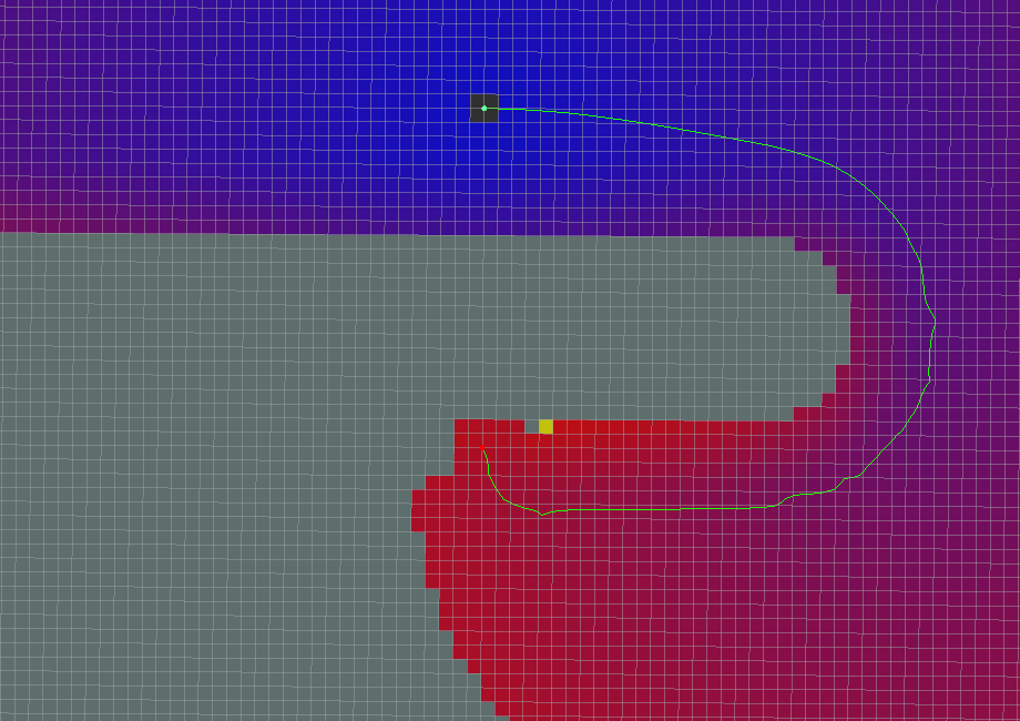
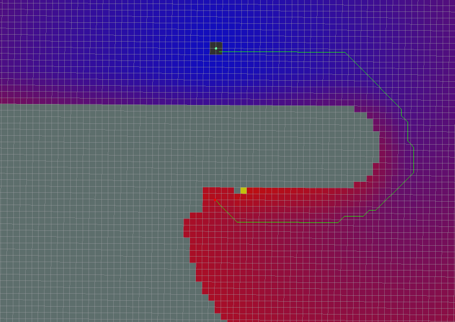
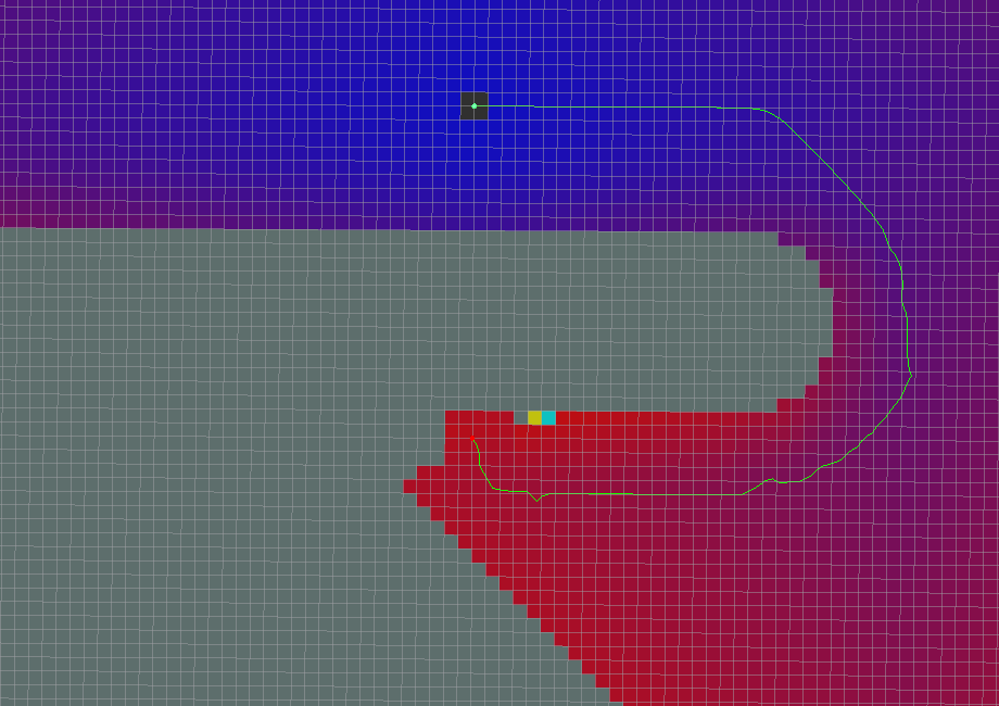
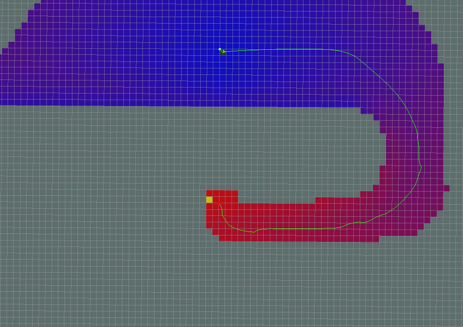
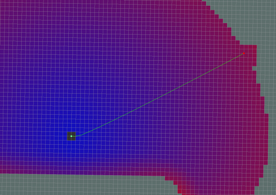
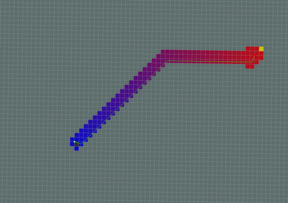
Global path planning algorithm renderings
- All parameters are default
- use_grid_path=True
- use_quadratic=False
- use_dijkstra=False
- Dijkstra
- A*
- old_navfn_behavior=True
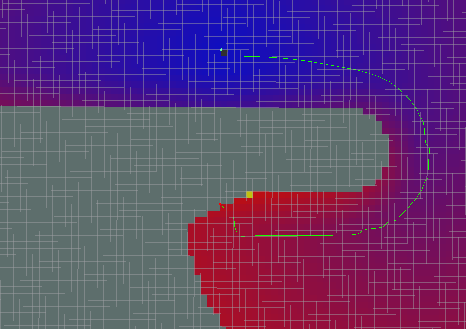
If it appears in the very first stage:
xxxxxxxxxx[ERROR] [1611670223.557818434, 295.312000000]: NO PATH![ERROR] [1611670223.557951973, 295.312000000]: Failed to get a plan from potential when a legal potential was found. This shouldn't happen.
This situation is related to the direction set by the robot. It is recommended to try the default [navfn] plugin for global path planning.
12.5.2 local_planner
nav_core::BaseLocalPlanner provides an interface for local path planners used in navigation. All local path planners written as move_base node plugins must adhere to this interface. Documentation on NavaCys::BaseLoCalPrnor's C++ API can be found here: BaseLocalPlanner documentation .
Local path planning plugin
- base_local_planner : Implements two local planning algorithms, Trajectory Rollout and DWA.
- dwa_local_planner : Compared to the DWA of base_local_planner, the modular DWA implementation has the advantage of a cleaner, easier-to-understand interface and more flexible y-axis variables.
- teb_local_planner : Implements the Timed-Elastic-Band method for online trajectory optimization.
- eband_local_planner : Implements the Elastic Band method on the SE2 manifold only for circular, differential drive, forward drive(not backward), omnidirectional robots.
- mpc_local_planner :Provides several model predictive control approaches embedded in the SE2 manifold
Comparison of TEB and DWA:
teb will adjust its orientation during the movement. When it reaches the target point, usually the orientation of the robot is also the orientation of the target and does not need to rotate.
dwa first reaches the target coordinate point, and then rotates to the target orientation in situ.
For a two-wheel differential chassis, adjusting the orientation of the teb during movement will make the movement path unsmooth, and unnecessary backwards will occur when starting and reaching the target point, which is not allowed in some application scenarios. Because backing up may encounter obstacles. Rotating in place to a suitable orientation and then walking away is a more appropriate exercise strategy. This is also where teb needs to be optimized according to the scene.
1)dwa_local_planner
The dwa_local_planner package supports any robot whose chassis can be represented as a convex polygon or a circle. This package provides a controller that drives the robot to move in a plane. This controller connects the path planner to the robot. The planner uses the map to create a motion trajectory for the robot from the starting point to the target position, sending the dx, dy, dtheta velocities to the robot.
The basic idea of DWA algorithm
- Discrete sampling in robot control space(dx, dy, dtheta)
- For each sampling velocity, perform a forward simulation from the current state of the robot to predict what would happen if the sampling velocity were applied for a(short) period of time.
- Evaluate(score) each trajectory produced by the simulation ahead, using a metric that includes the following characteristics: approaching obstacle, approaching target, approaching global path, and speed. Illegal trajectories(trajectories that collide with obstacles) are discarded.
- The trajectory with the highest score is selected and the associated velocity is sent to the mobile robot.
- Clean the data and repeat.
A number of ROS parameters can be set to customize the behavior of dwa_local_planner::DWAPlannerROS. These parameters fall into several categories: robot configuration, target tolerance, forward simulation, trajectory scoring, oscillation prevention, and global planning. These parameters can be debugged using the dynamic_reconfigure tool to tune the local path planner in a running system.
xxxxxxxxxxDWAPlannerROS :# Robot Configuration Parametersacc_lim_x : 2.5acc_lim_y : 2.5acc_lim_th : 3.2max_vel_trans : 0.55min_vel_trans : 0.1max_vel_x : 0.55min_vel_x : 0.0max_vel_y : 0.1min_vel_y : -0.1max_rot_vel : 1.0min_rot_vel : 0.4# Goal Tolerance Parametersyaw_goal_tolerance : 0.05xy_goal_tolerance : 0.10latch_xy_goal_tolerance : false# Forward Simulation Parameterssim_time : 2.0sim_granularity : 0.025vx_samples : 6vy_samples : 1vth_samples : 20controller_frequency : 5.0# Trajectory Scoring Parameterspath_distance_bias : 90.0 # 32.0goal_distance_bias : 24.0 # 24.0occdist_scale : 0.3 # 0.01forward_point_distance : 0.325 # 0.325stop_time_buffer : 0.2 # 0.2scaling_speed : 0.20 # 0.25max_scaling_factor : 0.2 # 0.2publish_cost_grid : false# Oscillation Prevention Parametersoscillation_reset_dist : 0.05 # default 0.05# Global Plan Parametersprune_plan : false
Robot configuration parameters
- acc_lim_x: The x acceleration limit of the robot(unit: m/s^2).
- acc_lim_y: The absolute value of the acceleration in the y direction(unit: m/s^2). Note: This value only needs to be configured for robots that move in all directions.
- acc_lim_th: The absolute value of the rotational acceleration(unit: rad/s^2).
- max_vel_trans: The absolute value of the maximum translation velocity(unit: m/s).
- min_vel_trans: The absolute value of the minimum translation velocity(unit: m/s).
- max_vel_x: The absolute value of the maximum velocity in the x direction(unit: m/s).
- min_vel_x: the absolute value of the minimum value in the x direction(unit: m/s), if it is a negative value, it means that it can go back.
- max_vel_y: The absolute value of the maximum velocity in the y direction(unit: m/s).
- min_vel_y: The absolute value of the minimum velocity in the y direction(unit: m/s).
- max_rot_vel: The absolute value of the maximum rotation speed(unit: rad/s).
- min_rot_vel: The absolute value of the minimum rotation speed(unit: rad/s).
Target tolerance parameter
- yaw_goal_tolerance: The allowable error of the yaw angle when reaching the target point(unit: rad).
- xy_goal_tolerance: Tolerance(unit: m) allowed within the x&y distance when reaching the goal point.
- latch_xy_goal_tolerance: set to true, if it reaches the fault tolerance distance, the robot will rotate in place, even if the rotation runs out of the fault tolerance distance.
Forward Simulation Parameters
- sim_time: Time to simulate the trajectory forward(unit: s).
- sim_granularity: The step size(unit: m) between points on a given trajectory.
- vx_samples: The number of sampling points in the x-direction velocity space.
- vy_samples: The number of sampling points in the y-direction velocity space.
- vth_samples: The number of velocity space sampling points in the rotation direction.
- controller_frequency: The frequency at which this controller is called(unit: Hz).
Trajectory Scoring Parameters
- path_distance_bias: Weights that define how close the controller is to a given path.
- goal_distance_bias: A weight that defines how close the controller is to the local goal point.
- occdist_scale: Defines the weight of the controller to avoid obstacles.
- forward_point_distance: The distance(unit: m) from the robot center point to the placement of the extra scoring point.
- stop_time_buffer: The length of time(unit: s) that the robot must stop in advance before collision.
- scaling_speed: Start scaling the speed of the robot chassis(unit: m/s).
- max_scaling_factor: The maximum scaling parameter of the robot chassis.
- publish_cost_grid: Whether to publish the cost grid of the planner when planning the path. If set to true, then messages of type sensor_msgs/PointCloud2 will be published on the topic ~/cost_cloud.
Anti-vibration parameters
- oscillation_reset_dist: How far the robot moves to reset the oscillation mark(unit: m).
Global Planning Parameters
- prune_plan: When the robot moves forward, whether to clear the trajectory 1m behind it.
2)teb_local_planner
teb_local_planner is an optimization-based local trajectory planner. Support difference model, car-like model. This software package implements an online optimal local trajectory planner for mobile robot navigation and control, which efficiently obtains the optimal trajectory by solving a sparse scalar multi-objective optimization problem. Users can provide weights to optimization problems to specify behavior in case of conflicting goals.
The teb_local_planner package allows users to set parameters to customize the behavior. These parameters are grouped into categories: robot configuration, target tolerance, trajectory configuration, obstacles, optimization, planning in unique topologies, and other parameters. Some of them were selected to meet basic local planners. Many(but not all) parameters can be modified at runtime using rqt_reconfig.
Local path planner teb_local_planner_params.yaml
xxxxxxxxxxTebLocalPlannerROS # Miscellaneous Parameters map_frame:odom odom_topic odom # Robot acc_lim_x 0.5 acc_lim_theta 0.5 max_vel_x 0.4 max_vel_x_backwards 0.2 max_vel_theta 0.3 min_turning_radius 0.0 footprint_model type "point" # GoalTolerance xy_goal_tolerance 0.2 yaw_goal_tolerance 0.1 free_goal_vel False # Trajectory dt_ref 0.3 dt_hysteresis 0.1 min_samples 3 global_plan_overwrite_orientation True allow_init_with_backwards_motion False max_global_plan_lookahead_dist 3.0 global_plan_viapoint_sep -1 global_plan_prune_distance 1 exact_arc_length False feasibility_check_no_poses 5 publish_feedback False # Obstacles min_obstacle_dist 0.25 inflation_dist 0.6 include_costmap_obstacles True costmap_obstacles_behind_robot_dist 1.5 obstacle_poses_affected 15 dynamic_obstacle_inflation_dist 0.6 include_dynamic_obstacles True costmap_converter_plugin "" costmap_converter_spin_thread True costmap_converter_rate 5 # Optimization no_inner_iterations 5 no_outer_iterations 4 optimization_activate True optimization_verbose False penalty_epsilon 0.1 obstacle_cost_exponent 4 weight_max_vel_x 2 weight_max_vel_theta 1 weight_acc_lim_x 1 weight_acc_lim_theta 1 weight_kinematics_nh 1000 weight_kinematics_forward_drive 1 weight_kinematics_turning_radius 1 weight_optimaltime 1 # must be > 0 weight_shortest_path 0 weight_obstacle 100 weight_inflation 0.2 weight_dynamic_obstacle 10 weight_dynamic_obstacle_inflation 0.2 weight_viapoint 1 weight_adapt_factor 2 # Parallel Planning enable_homotopy_class_planning True enable_multithreading True max_number_classes 4 selection_cost_hysteresis 1.0 selection_prefer_initial_plan 0.9 selection_obst_cost_scale 100.0 selection_alternative_time_cost False roadmap_graph_no_samples 15 roadmap_graph_area_width 5 roadmap_graph_area_length_scale 1.0 h_signature_prescaler 0.5 h_signature_threshold 0.1 obstacle_heading_threshold 0.45 switching_blocking_period 0.0 viapoints_all_candidates True delete_detours_backwards True max_ratio_detours_duration_best_duration 3.0 visualize_hc_graph False visualize_with_time_as_z_axis_scale False # Recovery shrink_horizon_backup True shrink_horizon_min_duration 10 oscillation_recovery True oscillation_v_eps 0.1 oscillation_omega_eps 0.1 oscillation_recovery_min_duration 10 oscillation_filter_duration 10 Robot configuration
acc_lim_x: The maximum translational acceleration of the robot(unit: m/s^2).
acc_lim_theta: The maximum angular acceleration of the robot(unit: rad/s^2).
max_vel_x: The maximum translation speed of the robot(unit: m/s).
max_vel_x_backwards: The maximum absolute translation speed of the robot when traveling backwards(unit: m/s).
max_vel_theta: The maximum angular velocity of the robot(unit: rad/s).
The following parameters are only relevant for carlike robots
min_turning_radius: Minimum turning radius for carlike robots(for differential robots, set to zero).
wheelbase: The distance between the rear axle and the front axle. For rear-wheeled robots, this value may be negative(only required if /cmd_angle_instead_rotvel is set to true).
cmd_angle_instead_rotvel: Replace the rotation speed in the command speed information with the corresponding steering angle [-pi/2, pi/2].
The following parameters are only relevant for full robots: New parameters in ROS dynamics
max_vel_y: The robot's maximum strafing velocity(should be zero for non-omnidirectional robots!).
acc_lim_y: The maximum strafing acceleration of the robot.
The following parameters are relevant to the chassis model used for optimization
footprint_model:
type: "point":
Parameter [footprint_model]
Specifies the robot schematic model type used for optimization. The different types are "point", "circular", "line", "two_circles", "polygon". The type of model significantly affects the computation time required.
footprint_model/radius: This parameter is only relevant for the "circular" type. It contains the radius of the circle. The center of the circle is on the axis of rotation of the robot.
footprint_model/line_start: This parameter is only relevant for the "line" type. It contains the starting coordinates of the line segment.
footprint_model/line_end: This parameter is only relevant for the "line" type. It contains the endpoint coordinates of the line segment.
footprint_model/front_offset: This parameter is only relevant for the ''two_circles'' type. It describes how much the center of the front circle moves along the robot's x-axis. Suppose the robot's axis of rotation is at [0,0].
footprint_model/front_radius: This parameter is only relevant for the ''two_circles'' type. .It contains the radius of the front circle.
footprint_model/rear_offset: This parameter is only relevant for the ''two_circles'' type. It describes how much the center of the back circle moves along the robot's negative x-axis. Suppose the robot's axis of rotation is at [0,0].
footprint_model/rear_radius: This parameter is only relevant for the ''two_circles'' type. It contains the radius of the back circle.
footprint_model/vertices: This parameter is only relevant for the "polygon" type. It contains a list of polygon vertices(2D coordinates of each vertex). Polygons are always closed: don't repeat the first vertex at the end.
is_footprint_dynamic: If true, the footprint is updated before the trajectory feasibility is checked.
target tolerance
- yaw_goal_tolerance: The allowable error of the yaw angle when reaching the target point(unit: rad).
- xy_goal_tolerance: Tolerance(unit: m) allowed within the x&y distance when reaching the goal point.
- free_goal_vel: Removes the goal velocity constraint, allowing the robot to reach the goal at maximum speed.
Track configuration
- dt_ref: Desired trajectory temporal resolution.
- dt_hysteresis: The hysteresis to be automatically resized based on the current temporal resolution, typically around 10% of dt_ref is recommended.
- max_samples: Minimum number of samples(should always be greater than 2).
- global_plan_overwrite_orientation: Overwrite the orientation of the local sub-goals provided by the global planner(as they usually only provide 2D paths)
- global_plan_viapoint_sep: If positive, via points are extracted from the global plane(path following mode). This value determines the resolution of the reference path(minimum spacing between each successive via point along the global plane, if negative: disabled).
- max_global_plan_lookahead_dist: Specifies the maximum length(cumulative Euclidean distance) of a subset of the global plan considered when optimizing. The actual length is determined by the size of the local costmap and the logical connection of this maximum bound. Set to zero or negative to disable this limit.
- force_reinit_new_goal_dist: Reinitialize the trajectory if the update interval of the previous goal exceeds the specified number of meters(skip warm start).
- feasibility_check_no_poses: Specifies which poses in the prediction plan should be checked for feasibility each sampling interval.
- publish_feedback: publish planner feedback with full trajectory and list of active obstacles(should only be enabled when evaluating or debugging)
- shrink_horizon_backup: Allows the planner to temporarily shrink the scope(50%) when problems are automatically detected(e.g. infeasible).
- allow_init_with_backwards_motion: If true, base trajectories may be initialized with backwards motion if the target is behind the starting point in the local costmap(recommended only if the robot is equipped with backsensors).
- exact_arc_length: If true, the planner uses the exact arc length(-> increased cpu time) in velocity, acceleration and steering rate calculations, otherwise uses the Euclidean approximation.
- shrink_horizon_min_duration: Specifies the minimum duration to shrink the horizon in case an infeasible trajectory is detected.
obstacle
- min_obstacle_dist: The minimum expected distance from the obstacle(unit: m).
- include_costmap_obstacles: Specifies whether local costmap obstacles should be considered.
- costmap_obstacles_behind_robot_dist: Limit the occupied local costmap obstacles(unit: m) that the robot considers when planning behind it.
- obstacle_poses_affected: Each obstacle position is attached to the closest pose on the trajectory to maintain distance.
- inflation_dist: Buffer around non-zero penalty cost obstacles(should be larger than minimum obstacle distance in order to take effect).
- include_dynamic_obstacles: If this parameter is set to true, the motion of obstacles with non-zero velocity is predicted and considered by the constant velocity model during optimization.
- legacy_obstacle_association: Modified strategy for connecting trajectory poses with obstacles for optimization.
The following parameters are only costmap_converter plugin is required:
costmap_converter_plugin: ""
Defines the plugin name for converting costmap cells to points/lines/polygons. Set an empty string to disable conversion so that all cells are treated as point obstacles.
costmap_converter_spin_thread: If set to true, costmap_converter will call its callback queue in a different thread
costmap_converter_rate: Defines the rate at which the costmap_converter plugin processes the current costmap frequency(unit: Hz).
optimization
- no_inner_iterations: The actual number of solver iterations called in each outer loop iteration.
- no_outer_iterations: Each outer loop iteration automatically resizes the trajectory according to the desired time resolution dt_ref and calls the internal optimizer(no internal iterations are performed).
- penalty_epsilon: Adds a small safety margin to the hard-constrained approximated penalty function.
- weight_max_vel_x: The optimized weight that satisfies the maximum allowable translation velocity.
- weight_max_vel_theta: The optimization weight that satisfies the maximum allowable angular velocity.
- weight_acc_lim_x: The optimized weight that satisfies the maximum allowable translational acceleration.
- weight_acc_lim_theta: The optimized weight that satisfies the maximum allowable angular acceleration.
- weight_kinematics_nh: Optimized weights that satisfy nonholonomic kinematics.
- weight_kinematics_forward_drive: Optimized weight for forcing the robot to choose only the forward direction(positive translation speed).
- weight_kinematics_turning_radius: Implement optimized weight for minimum turning radius(only for carlike robots).
- weight_optimaltime: Shorten the optimal weight of the trajectory with respect to transition/execution time
- weight_obstacle: The optimized weight to keep the minimum distance from the obstacle.
- weight_viapoint: Optimization weight used to minimize distance to via points(respectively reference paths).
- weight_inflation: Optimization weight for inflation penalty(should be small).
- weight_adapt_factor: Some special weights(current weights) are repeatedly scaled by this factor in each outer TEB iteration.
planning
- enable_homotopy_class_planning: Activates parallel planning in unique topologies.
- enable_multithreading: activates multithreading to plan each trajectory in a different thread.
- max_number_classes: Specifies the maximum number of distinct trajectories considered.
- selection_cost_hysteresis: Specifies how much trajectory cost a new candidate trajectory must have to be selected.
- selection_obst_cost_scale: Additional extended barrier cost conditions.
- selection_viapoint_cost_scale: Additional extended via point cost conditions.
- selection_alternative_time_cost: If true, the time cost(sum of squared time differences) will be replaced by the total transition time.
- roadmap_graph_no_samples: Specifies the number of samples generated to create the roadmap.
- roadmap_graph_area_width: Random keypoints/waypoints are sampled in a rectangular area between origin and target(unit: m).
- obstacle_heading_threshold: Specifies the value of the scalar product between obstacle headings and goal headings to consider them(obstacles) when exploring.
- visualize_hc_graph: Visualize a graph created to explore unique trajectories.
- viapoints_all_candidates: If true, all trajectories of different topologies will be connected to the via point set, otherwise, only trajectories that share the same topology as the initial/global plan will be connected to it.
- switching_blocking_period: Specifies the duration(unit: s) that needs to expire before switching to the new equivalence class is allowed.