Welcome to ROSMASTER X3 Plus repository
1.Lidar basic-SLAM
1 Lidar basic-SLAM
1 Lidar basic-SLAM1.1 Overview 1.2 Silan Lidar components 1.2.1Laser 1.2.2 Receiver 1.2.3 Signal processing unit 1.2.4 Rotating mechanism 1.3 Principle of single-line lidar 1.3.1 Triangulation method 1 Direct shot 2 oblique shot 1.3.2 TOF time-of-flight ranging method 1.4 Lidar A1M8 1.5 Application scenarios 1.6 function package rplidar ros 1.6.1 Remap the USB serial port 1.6.2 code testing 1.6.3 Mapping test 1.7 source code analysis
Slam LIDAR tutorial materials: http://www.slamtec.com/cn/Support
Lidar Technology Email Address: support@slamtec.com
Lidar wiki: http://wiki.ros.org/rplidar
Lidar SDK: https://github.com/Slamtec/rplidar_sdk
Lidar ROS: https://github.com/Slamtec/rplidar_ros
Lidar Tutorial: https://github.com/robopeak/rplidar_ros/wiki
- For different types of Lidar
Before using lidar, you need to declare the [RPLIDAR_TYPE] variable in advance in the [.bashrc] file according to different Lidar models. Open the [.bashrc] file
xxxxxxxxxxsudo vim ~/.bashrc
If there is no following sentence in [.bashrc], you need to manually add it according to the purchased Lidar model. If there is this sentence, directly modify the Lidar model. For example: Silan a1 lidar
xxxxxxxxxxexport RPLIDAR_TYPE = a1 # a1, a2, a3, s1, s2
Note: For rosmaster series cars equipped with S2L lidar, the lidar startup mode is the same as S2, which can be changed to S2.
After modification, refresh the environment variables
xxxxxxxxxxsource ~/.bashrc
1.1 Overview
Single-line LiDAR refers to the single-line Lidar that the beam emitted by the laser source is divided into triangular ranging and TOF LiDAR, and is mainly used in the field of robotics. It has fast scanning speed, strong resolution and high reliability. Compared with multi-line lidar, single-line lidar has faster response in angular frequency and sensitivity, so it is more accurate in ranging distance and accuracy of obstacles.
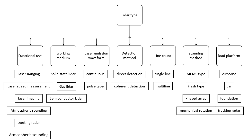
1.2 Silan Lidar components
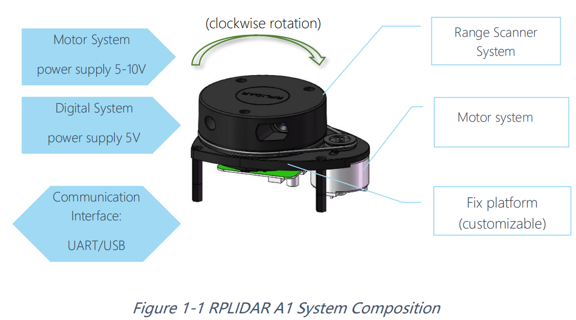
Taking Silan's single-line lidar as an example, it is mainly composed of four core components: laser, receiver, signal processing unit and rotating mechanism.
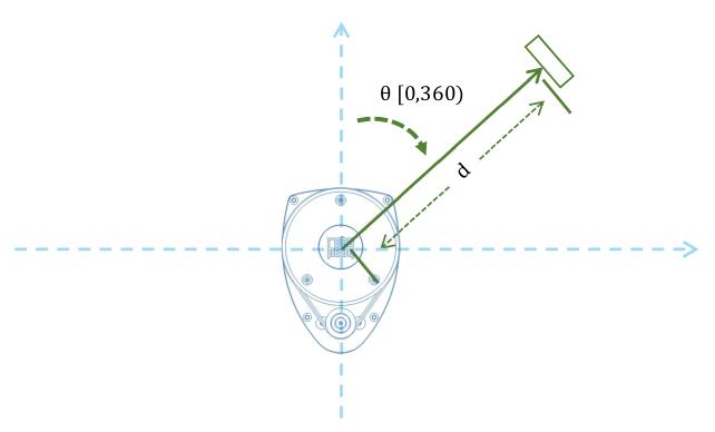
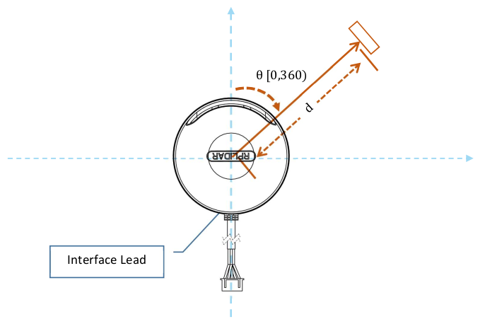
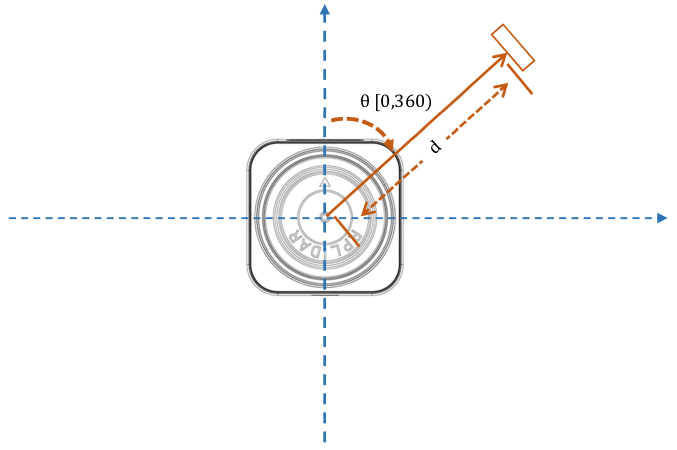
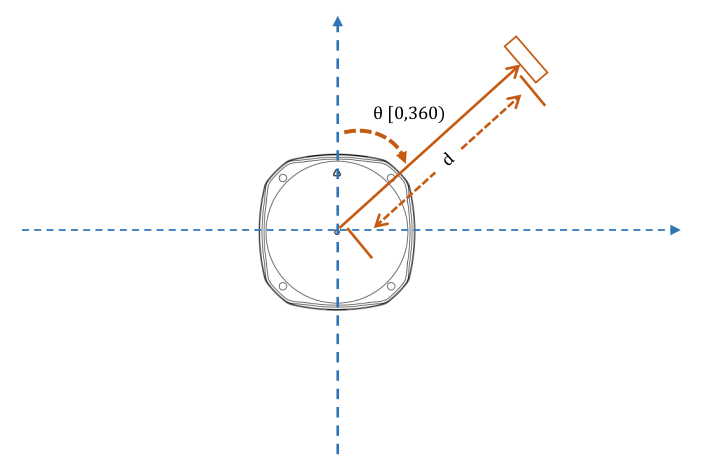
RPLIDAR adopts a coordinate system that follows the left-hand rule. The front of the sensor is defined as the x-axis of the coordinate system. The origin of the coordinate system is the rotation center of the ranging core, and the rotation angle increases with the clockwise rotation. The specific coordinate system definition is shown in the following figure:(For details, please refer to the supporting manual)
| A1 | A2 A3 |
|---|---|
 |  |
| S1 | S2 |
 |  |
1.2.1Laser
The laser is the laser emitting mechanism in the lidar. During operation, it lights up in pulses. Silan Technology's RPLIDAR A3 series Lidar will turn on and off 16,000 times per second.
1.2.2 Receiver
After the laser emitted by the laser irradiates the obstacle, the reflected light will be concentrated on the receiver through the lens group through the reflection of the obstacle.
1.2.3 Signal processing unit
The signal processing unit is responsible for controlling the emission of the laser and the processing of the signal received by the receiver. Based on this information, the distance information of the target object is calculated.
1.2.4 Rotating mechanism
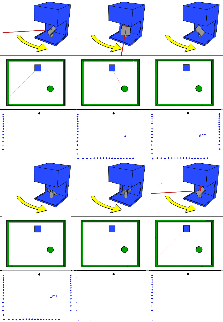
The above three components constitute the core components of the measurement. The rotating mechanism is responsible for rotating the above-mentioned core components at a stable rotational speed, so as to scan the plane and generate real-time plan information.
1.3 Principle of single-line lidar
Refer to the following figure for the working principle of the single-line mechanical rotating mechanism Lidar:
1.3.1 Triangulation method
The laser triangulation method mainly uses a beam of laser light to irradiate the measured target at a certain incident angle, the laser is reflected and scattered on the surface of the target, and the reflected laser is collected and imaged by a lens at another angle, and the spot is imaged on a CCD(Charge-coupled Device, photosensitive coupling component) position sensor. When the measured object moves along the laser direction, the light spot on the position sensor will move, and its displacement corresponds to the moving distance of the measured object. Therefore, the distance between the measured object and the baseline can be calculated from the displacement distance of the light spot through algorithm design. value. Since the incident light and the reflected light form a triangle, the geometric triangle theorem is used for the calculation of the spot displacement, so the measurement method is called the laser triangulation method.
According to the angle relationship between the incident beam and the surface normal of the measured object, the laser triangulation method can be divided into two types: oblique type and direct type.
1 Direct shot
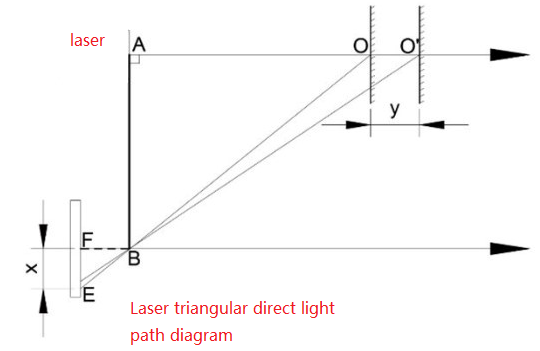
As shown in Figure 1, when the laser beam is perpendicular to the surface of the object to be measured, that is, when the incident light beam is collinear with the normal to the surface of the object to be measured, it is a direct laser triangulation method.
2 oblique shot
When the angle between the incident laser beam and the normal to the surface of the object to be measured in the optical path system is less than 90°, the incident method is oblique. The optical path diagram shown in FIG. 2 is an oblique light path diagram of the laser triangulation method.
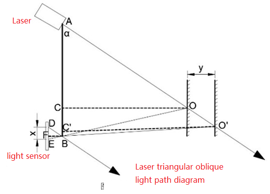
The laser emitted by the laser is incident on the surface of the object to be measured at a certain angle to the normal of the object surface, and the reverse(scattered) light is condensed and imaged by the lens at B, and finally collected by the photosensitive unit.
Whether it is a direct-shot or oblique-shot laser triangulation method, high-precision, non-contact measurement of the object to be measured can be achieved, but the resolution of the direct-shot type is not as high as that of the oblique-shot type.
Silan Technology's RPLIDAR series lidar also adopts the oblique laser triangulation method. In each ranging process, the RPLIDAR series lidar will emit a modulated infrared laser signal, and the reflected light generated by the laser signal after irradiating the target object will be received by the RPLIDAR vision acquisition system, and then processed by the DSP embedded in the RPLIDAR. The real-time calculation of the irradiated target object and the RPLIDAR and the current included angle information will be output from the communication interface. Driven by the motor mechanism, the ranging core of RPLIDAR will rotate clockwise, thus realizing 360-degree omnidirectional scanning ranging detection of the surrounding environment.
1.3.2 TOF time-of-flight ranging method
TOF lidar is based on measuring the time of flight of light to obtain the distance of the target. Its working principle is mainly as follows: a beam of modulated laser signal is sent out through the laser transmitter, the modulated light is reflected by the measured object and received by the laser detector, and the distance to the target can be calculated by measuring the phase difference between the emitted laser and the received laser..
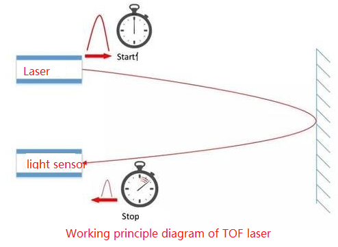
Under the condition of long-distance objects, its measurement accuracy is still accurate and stable. At the same time, due to the characteristics of ultra-short light pulse, TOF Lidar is not inferior in anti-light interference ability, and can achieve stable ranging and high-precision mapping even under strong light of 60Klx outdoors.
In general, triangular ranging lidar and TOF lidar have their own difficulties in implementation. In principle, the ranging distance of TOF Lidar is farther. The manufacturing cost of triangular ranging lidar is relatively low, and the accuracy can meet most industrial-grade civil requirements, so it has also attracted much attention in the industry.
1.4 Lidar A1M8
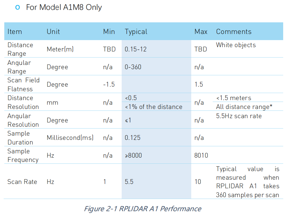
As can be seen from the above figure, parameters such as measurement radius, sampling speed, rotation speed, and angular resolution are important indicators of Lidar performance.
| index | describe |
|---|---|
| Ranging radius | The measuring distance range of the Lidar |
| Ranging sample rate | How many times the ranging output is made in one second |
| scanning frequency | How many scans the Lidar makes in one second |
| Angular resolution | Angular stepping of two adjacent ranges |
| Measurement Resolution/Accuracy | The minimum distance change can be perceived |
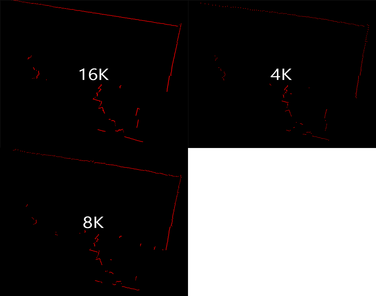
A higher scanning frequency can ensure that the robot equipped with lidar can move at a faster speed and ensure the quality of map construction. However, increasing the scanning frequency is not as simple as simply accelerating the rotation of the internal scanning motor of the lidar, and correspondingly, it is necessary to increase the sampling rate of ranging. Otherwise, when the sampling frequency is fixed, the faster scanning speed will only reduce the angular resolution. In addition to ranging distance and scanning frequency, parameters such as measurement resolution and mapping accuracy are equally important for lidar performance. These are important parameters to ensure that the robot can have stable performance.
1.5 Application scenarios
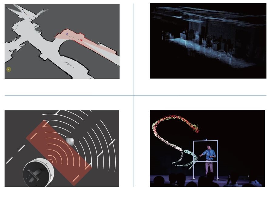
Thanks to the advancement of lidar technology, the measurement radius, ranging frequency, range resolution and angular resolution of lidar have been greatly improved, which can help various applications to obtain larger scenes and richer contour information. It plays an indispensable and important role in many fields such as autonomous positioning and navigation of robots, space environment mapping and security.
1.6 function package rplidar ros
Clone this project into the workspace's src folder and run catkin_make to build rplidarNode and rplidarNodeClient.
1.6.1 Remap the USB serial port
When starting the Lidar function package, it may encounter that the serial port permission is not executable. There are two solutions: 1) Add the permission directly; 2) Remap the USB serial port
1) Directly add permission method
This method only works this time.
Check the permissions of the rplidar serial port:
xxxxxxxxxxls -l/dev | grep ttyUSB
Add write permission:(eg /dev/ttyUSB0)
xxxxxxxxxxsudo chmod 777 /dev/ttyUSB0
2) Remapping USB serial port method
This method works for a long time.
Under the rplidar_ros feature package path, install USB port remapping
xxxxxxxxxx./scripts/create_udev_rules.sh
Re-plug and unplug the USB interface of the lidar, and use the following commands to modify the remapping:
xxxxxxxxxxls -l/dev | grep ttyUSB

1.6.2 code testing
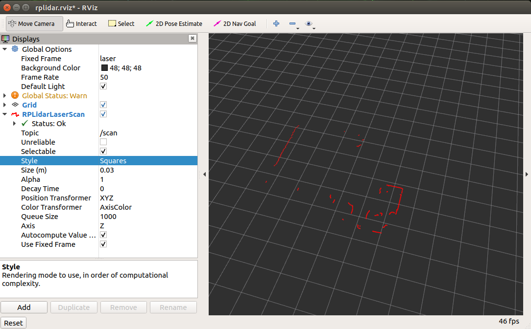
- Run the rplidar node and view it in rviz
xxxxxxxxxx#You need to enter docker first, perform this step more#If running the script to enter docker fails, please refer to 07.Docker-orin/05, Enter the robot's docker container~/run_docker.shroslaunch rplidar_ros view_rplidar.launch You should see scan results for rplidar in rviz.
- Run the rplidar node and use the test application to view
xxxxxxxxxx#You need to enter docker first, perform this step more#If running the script to enter docker fails, please refer to 07.Docker-orin/05, Enter the robot's docker container~/run_docker.shroslaunch rplidar_ros rplidar.launch # start the Lidar <Open another terminal and enter the same docker container
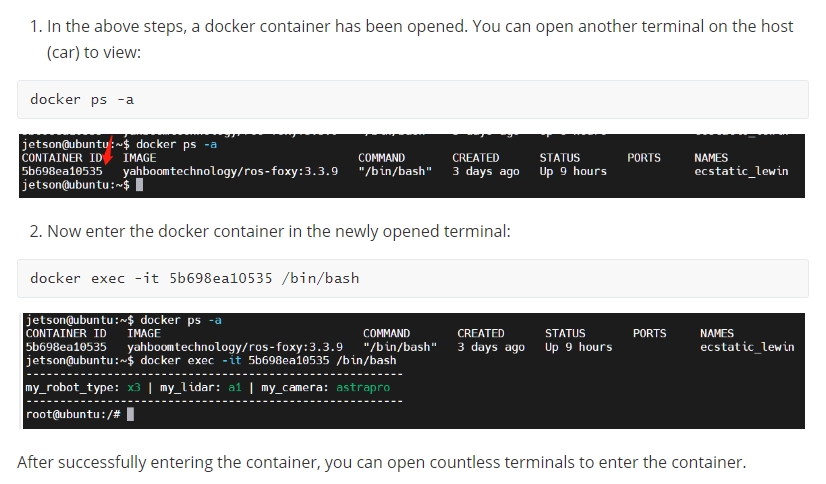
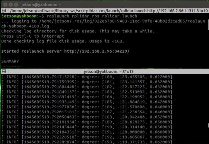
xxxxxxxxxxrosrun rplidar_ros rplidarNodeClient # Get and print Lidar data You should see scan results for rplidar in the console
1.6.3 Mapping test
xxxxxxxxxxroslaunch rplidar_ros test_gmapping.launch
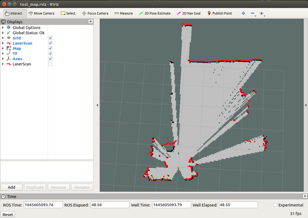
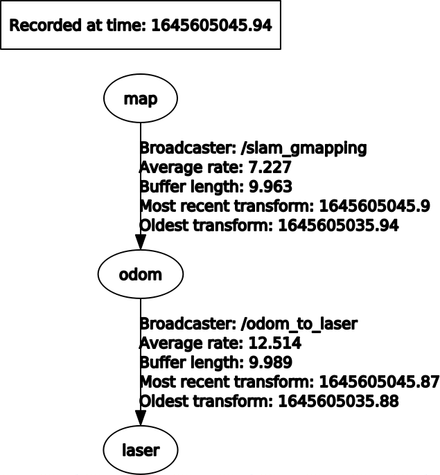
xxxxxxxxxxrosrun rqt_tf_tree rqt_tf_tree
xxxxxxxxxxrosrun rqt_graph rqt_graph

1.7 source code analysis
From the test in section [1.6], it can be seen that the data of the lidar does not have data in 360°, and there is a small gap, that is because the data behind the lidar is blocked.
rplidar.launch file
xxxxxxxxxx< launch > < arg name = "lidar_type" value = "$(env RPLIDAR_TYPE)" doc = "lidar_type type [a1,a2,a3,s1,s2]" /> < arg name = "frame_id" default = "laser" /> < arg name = "shielding_angle" default = "30" /> <!-- scan filtering node --> < node name = "scan_filter" pkg = "rplidar_ros" type = "scan_filter.py" output = "screen" respawn = "true" > < param name = "shielding_angle" type = "double" value = "$(arg shielding_angle)" /> </ node > < node name = "rplidarNode" pkg = "rplidar_ros" type = "rplidarNode" output = "screen" respawn = "true" > < param name = "serial_port" type = "string" value = "/dev/rplidar" /> < param name = "serial_baudrate" type = "int" value = "115200" if = "$(eval arg('lidar_type') == 'a1')" /> < param name = "serial_baudrate" type = "int" value = "115200" if = "$(eval arg('lidar_type') == 'a2')" /> < param name = "serial_baudrate" type = "int" value = "256000" if = "$(eval arg('lidar_type') == 'a3')" /> < param name = "serial_baudrate" type = "int" value = "256000" if = "$(eval arg('lidar_type') == 's1')" /> < param name = "serial_baudrate" type = "int" value = "1000000" if = "$(eval arg('lidar_type') == 's2')" /> < param name = "frame_id" type = "string" value = "$(arg frame_id)" /> < param name = "inverted" type = "bool" value = "false" /> < param name = "angle_compensate" type = "bool" value = "true" /> < param name = "scan_mode" type = "string" value = "Sensitivity" if = "$(eval arg('lidar_type') == 'a3')" /> < param name = "scan_mode" type = "string" value = " " unless = "$(eval arg('lidar_type') == 'a3')" /> < remap from = "scan" to = "scan_raw" /> </ node > </ launch > - Shielding_angle parameter: The angle of shielding Lidar data, the range is [0, 360], which can be adjusted according to the actual situation.
- gmapping is only applicable to points with less than 1440 2D laser points in a single frame. If the number of laser points in a single frame is greater than 1440, there will be a problem like [[mapping-4] process has died]. Therefore, when using S2 lidar, it is necessary to dilute the number of S2 points.
If you do not need to filter Lidar data, comment or delete the following content in the [rplidar.launch] file
xxxxxxxxxx <!-- scan filtering node --> < node name = "scan_filter" pkg = "rplidar_ros" type = "scan_filter.py" output = "screen" respawn = "true" > < param name = "shielding_angle" type = "double" value = "$(arg shielding_angle)" /> </ node > Then modify the [rplidarNode] node
xxxxxxxxxx< remap from = "scan" to = "scan_raw" /> <!-- 删除 --> < remap from = "scan" to = "scan" /> <!-- add--> Users can deal with it according to the actual situation.