Welcome to ROSMASTER X3 Plus repository
2.Robot PID debugging
2 Robot PID debugging
Note: Before the product leaves the factory, the PID has been debugged. It is not recommended to adjust it yourself, which may cause problems with subsequent functions. But you can learn
Learn debugging methods and operating steps.
According to different models, you only need to set the purchased model in [.bashrc], X1(ordinary four-wheel drive) X3(Mike wheel) X3plus(Mike wheel mechanical arm) R2(Ackerman differential) and so on. Section takes X3 as an example:
xxxxxxxxxx#You need to enter docker first, perform this step more#If running the script to enter docker fails, please refer to Jetson Orin-Docker/05, Enter the robot's docker container~/run_docker.sh#Multiple ros commands require multiple terminals to enter the same docker container for execution, please refer to Jetson Orin-Docker/05, Section 5.8 tutorialsudo vim .bashrc
Find the [ROBOT_TYPE] parameter and modify the corresponding model
export ROBOT_TYPE=X3 # ROBOT_TYPE: X1 X3 X3plus R2 X7 2.1 Start the chassis
2.1.1 function package path
~/yahboom_ws/src/yahboom_bringup/ 2.1.2 start
roslaunch yahboomcar_bringup bringup.launch # chassis start 
rosrun rqt_reconfigure rqt_reconfigure # parameter adjuster rqt_plot # rqt visualization tool rosrun yahboomcar_ctrl yahboom_keyboard.py # keyboard control node first view the source code Mcnamu_driver.py
def dynamic_reconfigure_callback(self, config, level): # self.car.set_pid_param(config['Kp'], config['Ki'], config['Kd']) # print("PID: ", config['Kp'], config['Ki'], config['Kd']) self.linear_max = config [ 'linear_max' ] self.linear_min = config [ 'linear_min' ] self.angular_max = config [ 'angular_max' ] self.angular_min = config [ 'angular_min' ] return config Find the line of self.car.set_pid_param and remove the comment # in front to debug the PID of the robot.
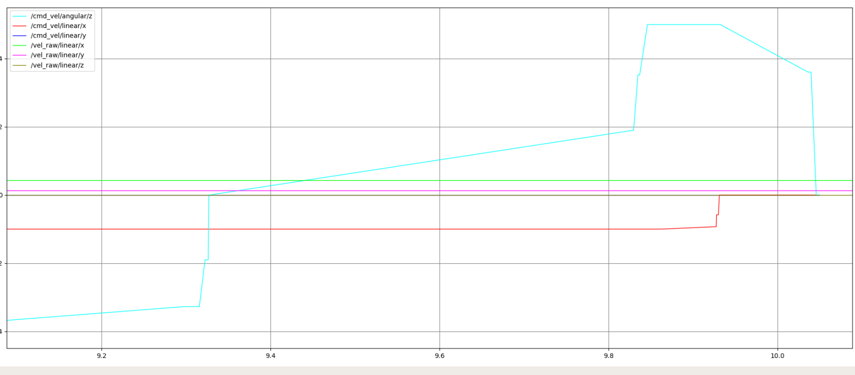
First select the debugging parameters, enter the name of each parameter as shown in the figure below, click [+] to add, and [-] to delete.
/cmd_vel/angular/z : target angular velocity
/cmd_vel/linear/x : Linear velocity in the x direction of the target
/cmd_vel/linear/y : Linear velocity in the target y direction
/vel_raw/angular/z : current angular velocity
/vel_raw/linear/x: The linear velocity in the current x direction
/vel_raw/linear/y: The linear velocity in the current y direction
Note: The speed in the y direction is only available for the Mecanum wheeler X1
In the rqt_reconfigure window, as shown in the figure, select the [driver_node] node. We only need to adjust the three parameters [Kp], [Ki], and [Kd], and do not adjust the others.

Debug steps:
In the keyboard control terminal, use the keys of the keyboard to drive the car to move [forward], [backward], [left turn], and [right turn].
Observe the change of the [rqt_plot] window image, so that the current angular velocity and the target angular velocity, and the current linear velocity and the target linear velocity are close to each other, and it is impossible to coincide. The target speed is ideal, without any interference, and the speed can be added instantly.
Use the keyboard [q], [z], [w], [x], [e], [c] to increase or decrease the speed, test the status of different speeds, and [t] to switch the X/Y axis direction of the trolley linear speed,【s】stop keyboard control. Note that the value range of the linear velocity of the XY axis of the car is v_x=[-1.0, 1.0], v_y=[-1.0, 1.0], and the value range of the angular velocity is v_z=[-5.0, 5.0].
Observe the changes of [rqt_plot], adjust the data of [Kp], [Ki], and [Kd] through [rqt_reconfigure], test multiple times, and select the optimal data.
Keyboard control instructions(before keyboard control, you need to click the mouse to open the keyboard control terminal before you can control it)
direction control
[I] or [I] 【 linear,0】 [U] or [U] 【linear,angular】 【,】 【-linear,0】 [O] or [O] 【linear,- angular】 【j】or【J】 【0, angular】 【m】or【M】 【- linear,- angular】 【l】or【L】 【0,- angular】 【.】 【 - linear,angular】 speed control
button speed change button speed change 【q】 Linear and angular velocity are both increased by 10% 【with】 Linear and angular velocities are both reduced by 10% 【in】 10% increase in line speed only 【x】 10% reduction in line speed only 【and】 10% increase in angular velocity only 【c】 Only the angular velocity is reduced by 10% 【t】 Line speed X-axis/Y-axis direction switching 【s】 stop keyboard control
After debugging, the PID is automatically stored in the PCB, just comment out the PID setting part according to the way of viewing the source code at first.
Note: PID debugging is required for other gameplays, and the theory is the same. Theoretical reference.