Welcome to ROSMASTER X3 Plus repository
1.Lidar basic-4ROS-EAI
1、Lidar basic-4ROS-EAI
1、Lidar basic-4ROS-EAI1.1、Overview1.2、4ROS Lidar1.2.1、Overview1.2.2、Product Features1.2.3、Application scenarios1.2.4、Polar coordinatesystem definition1.3、Single-line lidar principle1.3.1、Trigonometric ranging1、Direct shot2、Oblique shot1.3.2、TOF (Time-of-flight) ranging1.4、Using 4ROS lidar1.7、launch parsing
- For different models of lidar Before using LiDAR, it is necessary to declare the 【RPLIDAR_TYPE】 variable in advance in the 【. bashrc]】file based on different radar models. Open the 【. bashrc】 file.
sudo vim ~/.bashrc
If the following sentence is not present in 【. bashrc】, it needs to be manually added according to the purchased radar model. If this sentence is present, modify the radar model directly.
For example: 4ROS Lidar
xxxxxxxxxxexport RPLIDAR_TYPE=4ROS # a1, a2, a3, s1, s2,4ROS,X3
Note: For small cars equipped with X3 or X3Pro radar, the startup mode of the two radars should be the same, and both radars should be changed to X3.
After the modifications are completed, refresh the environment variables.
xxxxxxxxxxsource ~/.bashrc
1.1、Overview
Single-line LiDAR refers to the single-line radar that the beam emitted by the laser source is divided into triangular ranging and TOF LiDAR, and is mainly used in the field of robotics. It has fast scanning speed, strong resolution and high reliability. Compared with multi-line lidar, single-line lidar has faster response in angular frequency and sensitivity, so it is more accurate in ranging distance and accuracy of obstacles.
1.2、4ROS Lidar
1.2.1、Overview
YDLIDAR 4ROS lidar is a 360° 2D lidar (hereinafter referred to as: 4ROS). This product is based on the principle of pulsed ToF ranging, and is equipped with related optical, electrical, and algorithm designs to achieve high-frequency and high-precision distance measurement. At the same time, the mechanical structure rotates 360 degrees to continuously obtain angle information, thus realizing 360-degree scanning ranging , which outputs the point cloud data of the scanned environment.
1.2.2、Product Features
- Dust and waterproof, meet IP65
- 360 degree omnidirectional scanning, 5-12Hz adjustable scanning frequency
- High-speed ranging, ranging frequency 20000Hz
- Small ranging error, good ranging stability
- Strong anti-interference ability of ambient light
- Class I eye safety
1.2.3、Application scenarios
- Robot navigation and obstacle avoidance
- automated industry
- Area security
- Smart Transportation
- Environment scanning and 3D reconstruction
- Digital multimedia interaction
- Robot ROS teaching
1.2.4、Polar coordinatesystem definition
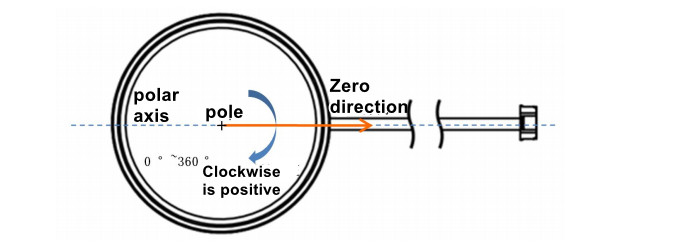
In order to facilitate secondary development, 4ROS internally defines a polar coordinate system. The system polar coordinates take the center of the 4ROS rotating core as the pole, the specified angle is clockwise as positive (top view), and the zero angle is located in the direction of the outlet of the 4ROS interface line, as shown below.
1.3、Single-line lidar principle
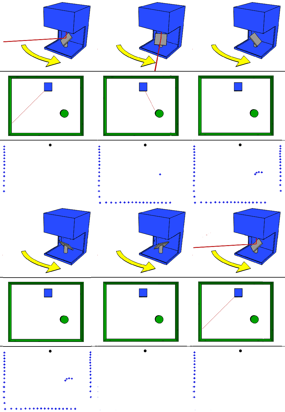
Working principle of the single-line lidar, as shown below.
1.3.1、Trigonometric ranging
According to the angle relationship between the incident beam and the surface normal of the measured object, the laser triangulation method can be divided into two types: oblique type and direct type.
1、Direct shot
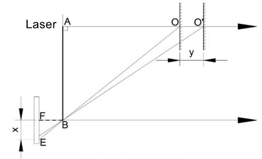
As shown below, when the laser beam is perpendicular to the surface of the object to be measured, that is, when the incident light beam is collinear with the normal to the surface of the object to be measured, it is a direct laser triangulation method.
2、Oblique shot
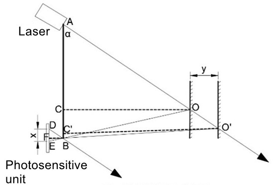
When the angle between the incident laser beam and the normal to the surface of the object to be measured in the optical path system is less than 90°, the incident method is oblique. The optical path diagram shown in FIG. 2 is an oblique light path diagram of the laser triangulation method.
1.3.2、TOF (Time-of-flight) ranging
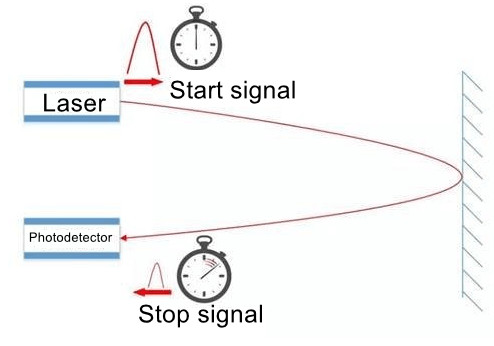
TOF lidar is based on measuring the time of flight of light to obtain the distance of the target. Its working principle is mainly as follows: a beam of modulated laser signal is sent out through the laser transmitter, the modulated light is reflected by the measured object and received by the laser detector, and the distance to the target can be calculated by measuring the phase difference between the emitted laser and the received laser. .
1.4、Using 4ROS lidar
Run following command in terminal.
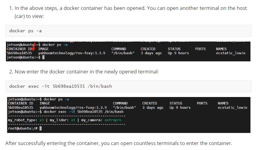
#You need to enter docker first, perform this step more#If running the script to enter docker fails, please refer to 07.Docker-orin/05, Enter the robot's docker container~/run_docker.shroslaunch ydlidar_ros_driver TG.launchRun following command in terminal. (We can print the topic data through the terminal to check whether the radar starts normally)
<Open another terminal and enter the same docker container
xxxxxxxxxxrostopic echo /scan
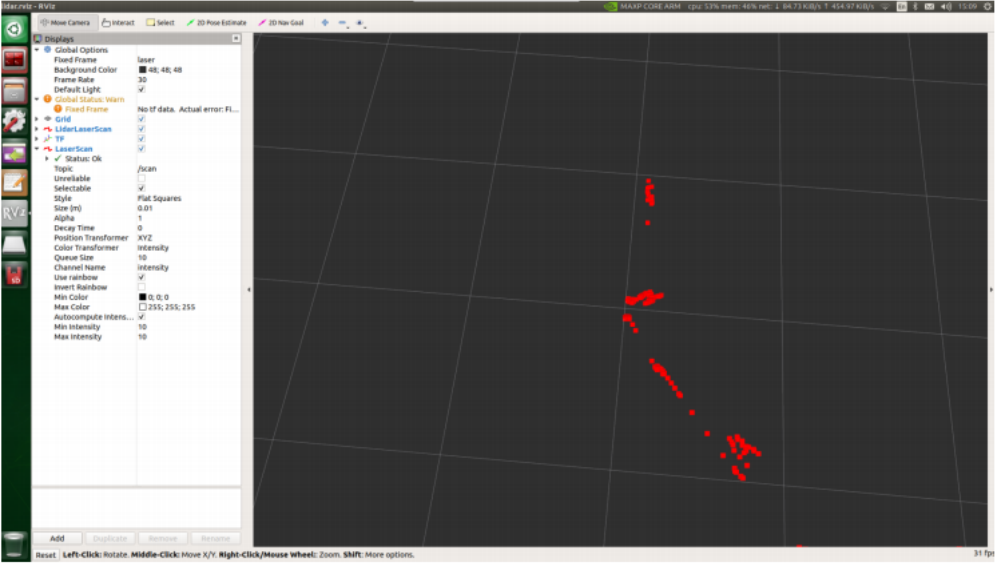
If you want to view the scan results in RVIZ, type in the terminal.
(Just enter the following commands, the above two commands do not require input)
xxxxxxxxxxroslaunch ydlidar_ros_driver lidar_view.launch
1.7、launch parsing
Code path:~/software/library_ws/src/ydlidar_ros_driver-master/launch
TG.launch file
x<launch> <arg name="frame_id" default="laser"/> <node name="ydlidar_lidar_publisher" pkg="ydlidar_ros_driver" type="ydlidar_ros_driver_node" output="screen" respawn="false" > <!-- string property --> <param name="port" type="string" value="/dev/ydlidar"/> <param name="frame_id" type="string" value="$(arg frame_id)"/> <!--param name="ignore_array" type="string" value="-90,90"/--> <param name="ignore_array" type="string" value=""/> <!--remap from="scan" to="scan_raw"/--> <!-- int property --> <param name="baudrate" type="int" value="512000"/> <!-- 0:TYPE_TOF, 1:TYPE_TRIANGLE, 2:TYPE_TOF_NET --> <param name="lidar_type" type="int" value="0"/> <!-- 0:YDLIDAR_TYPE_SERIAL, 1:YDLIDAR_TYPE_TCP --> <param name="device_type" type="int" value="0"/> <param name="sample_rate" type="int" value="20"/> <param name="abnormal_check_count" type="int" value="4"/> <!-- bool property --> <param name="resolution_fixed" type="bool" value="true"/> <param name="auto_reconnect" type="bool" value="true"/> <param name="reversion" type="bool" value="true"/> <param name="inverted" type="bool" value="true"/> <param name="isSingleChannel" type="bool" value="false"/> <param name="intensity" type="bool" value="false"/> <param name="support_motor_dtr" type="bool" value="false"/> <param name="invalid_range_is_inf" type="bool" value="true"/> <param name="point_cloud_preservative" type="bool" value="false"/> <!-- float property --> <param name="angle_min" type="double" value="-90" /> <param name="angle_max" type="double" value="90" /> <param name="range_min" type="double" value="0.01" /> <param name="range_max" type="double" value="50.0" /> <param name="frequency" type="double" value="10.0"/> </node> <!--node pkg="tf" type="static_transform_publisher" name="base_link_to_laser4" args="0.0 0.0 0.2 3.14 0.0 0.0 /base_footprint /laser 40" /--></launch>Main debugging parameters:
- angle_min parameter: the left angle of the radar
- angle_max parameter: the right angle of the radar
For other parameters, please refer to the official documentation,
ydlidar_ros_driver/README.md at master · YDLIDAR/ydlidar_ros_driver · GitHub