Welcome to K230 Vision Module repository
7.PWM
PWM
Introduction
In this tutorial, we will learn how to use the K230 GPIO interface to output PWM signals.
What is PWM signal?
PWM ( Pulse-width modulation ) is the abbreviation of pulse width modulation. Pulse width modulation is a digital encoding method for analog signal levels. Pulse width modulation PWM is a way to reduce the average power transmitted by the electrical signal by dispersing the effective electrical signal into discrete forms. Therefore, according to the area equivalence law, the waveform of the corresponding amplitude and frequency required for synthesis can be equivalently obtained by changing the time width of the pulse. The PWM signal adjusts the changes in the signal, energy, etc. by adjusting the change in the duty cycle.
wiring
Since the PWM signal cannot be seen directly, an oscilloscope is needed to view it. Please bring your own oscilloscope.
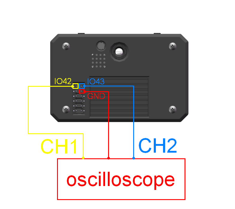
Connect channel 1 of the oscilloscope to IO42, channel 2 to IO43, and GND to ground.
Output PWM signal
Copy the following code into CanMV IDE and run
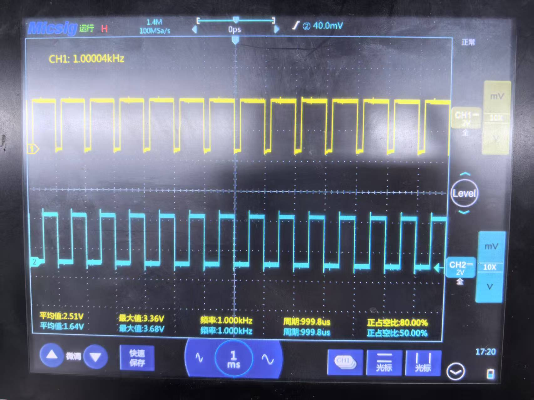
from machine import PWMfrom machine import FPIOAimport time# 实例化FPIOA# Instantiate FPIOAfpioa = FPIOA()# 设置PIN42为PWM通道0# Set PIN42 to PWM channel 0fpioa.set_function(42, fpioa.PWM0)# 实例化PWM通道0,频率为1000Hz,占空比为50%,默认使能输出# Instantiate PWM channel 0 with a frequency of 1000Hz, a duty cycle of 50%, and enable the output by defaultpwm0 = PWM(0, 1000, 50, enable = True)# 设置PIN43为PWM通道1# Set PIN43 as PWM channel 1fpioa.set_function(43, fpioa.PWM1)# 实例化PWM通道1,频率为1000Hz,占空比为50%,默认使能输出# Instantiate PWM channel 1 with a frequency of 1000Hz, a duty cycle of 50%, and enable the output by defaultpwm1 = PWM(1, 1000, 50, enable = True)# 关闭通道1输出# Turn off the output of Channel 1pwm1.enable(0)# 调整通道1频率为1000Hz# Adjust the frequency of Channel 1 to 1000Hzpwm1.freq(1000)# 调整通道1占空比为80%# Adjust the duty cycle of Channel 1 to 80%pwm1.duty(80)# 打开通道1输出# Open Channel 1 for outputpwm1.enable(1)# 阻止程序退出# Prevent the program from exitingwhile True: time.sleep(1)Then observe the level signal on the oscilloscope. As shown in the figure below: