Welcome to K230 Vision Module repository
5.Fruit sorting
Fruit sorting
1. Introduction
Please read the information in the 24-way servo driver board and the STM32 introductory tutorial first to understand how to burn the program and the basics of STM32. This will make it easier to learn and burn the following programs.
2. Equipment list
k230 x1
24-way servo driver board x1
7.4v battery x1
Aluminum alloy plate x1
3. Placement

The placement is as shown in the figure. You can choose our aluminum base frame as the base plate to fix the k230 and the gimbal, or you can choose a fixed base plate. The chassis can be glued to prevent the gimbal from moving too much and causing deviation. The k230 is fixed on the two-dimensional gimbal. When using the battery, if the gimbal rotates too much, you can moderately reduce the pid parameter.
4. Experimental preparation
First, build the 2D gimbal according to the 2D gimbal installation tutorial
Hardware wiring:

| 2D gimbal | 24-way servo driver board |
|---|---|
| X-axis servo | S1 |
| Y-axis servo | S2 |
| K230 vision module | 24-way motor driver board |
|---|---|
| 5V | 5V |
| GND | GND |
| TX | RX3 |
| RX | TX3 |
Note: When plugging in the servo cable, be sure to align the yellow cable with the yellow GPIO port of the 24-way servo driver board, and the brown cable with the black GPIO port of the 24-way servo driver board.
5. K230 key code analysis
In this section, we will use the classification model based on yolov5 training to perform simple fruit classification
Note: Training requires a GPU environment and has a certain degree of operational difficulty
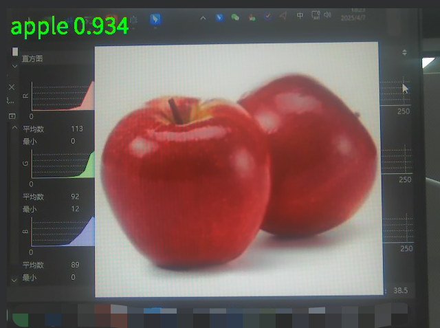
Identify apples
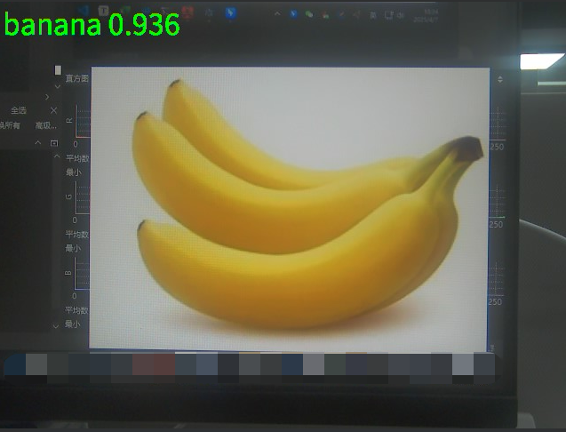
Identify bananas
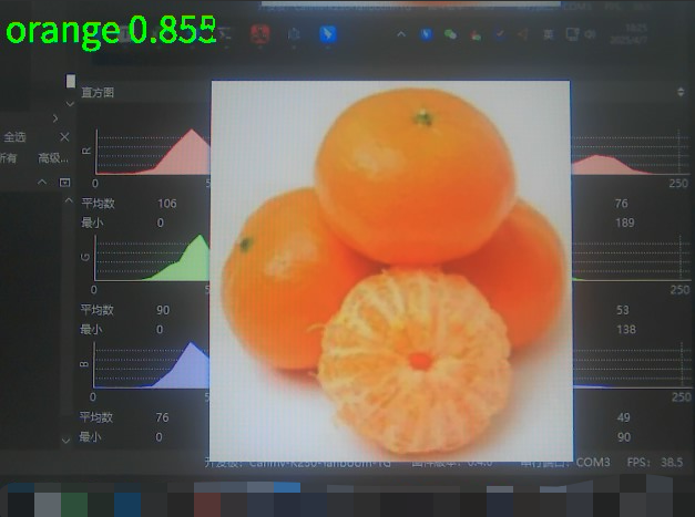
Identify oranges
Main working principle:
Get real-time video stream from the camera
Preprocess each frame and adjust the size to adapt to the model input requirements
Send the processed image to the neural network for reasoning
Filter the classification results according to the confidence threshold
Draw the recognition results on the display interface
Loop to process the next frame
Import dependencies
from libs.PipeLine import PipeLine, ScopedTimingfrom libs.YOLO import YOLOv5import os,sys,gcimport ulab.numpy as npimport image
PipeLine: Processing image pipelineScopedTiming: Performance timing toolYOLOv5: Encapsulates the reasoning interface of the YOLO modelulab.numpy: NumPy compatible library under MicroPython, optimized for embedded devices
Configuration initialization
xxxxxxxxxxrgb888p_size=[1280,720] # Original image sizedisplay_size=[640,480] # Display sizekmodel_path="/sdcard/kmodel/fruit_cls.kmodel" # Model pathlabels = ["apple","banana","orange"] # Classification labelconfidence_threshold = 0.7 # Confidence thresholdmodel_input_size=[224,224] # Model input size
Pipeline and model instantiation
xxxxxxxxxxpl=PipeLine(rgb888p_size=rgb888p_size,display_size=display_size,display_mode="lcd")pl.create()yolo=YOLOv5(task_type="classify",mode="video",kmodel_path=kmodel_path,labels=labels,rgb888p_size=rgb888p_size,model_input_size=model_input_size,display_size=display_size,conf_thresh=confidence_threshold,debug_mode=0)yolo.config_preprocess()
Main loop
xxxxxxxxxxtry:while True:os.exitpoint()with ScopedTiming("total",1):# Frame-by-frame reasoningimg=pl.get_frame() res=yolo.run(img)flag=res[0]if flag == -1:uart.write(bytearray([0x55,0xaa,0x00,0xfa]))if flag == 0:uart.write(bytearray([0x55,0xaa,0xff,0xfa]))yolo.draw_result(res,pl.osd_img)pl.show_image()gc.collect()
5. Exception handling and resource release
xxxxxxxxxxexcept Exception as e:sys.print_exception(e)finally:yolo.deinit()pl.destroy()
6. stm32 key code analysis
control.c
xuint8_t get_active(){uint8_t lable ,ret=0;if(DataDecode2(&Uart3_RingBuff,&lable) == 0){if(lable == 0x00){rec_step_p[0][0] =1;}
else if(lable ==0xff){rec_step_p[0][1] =1;
}}
return ret;}
This code converts and receives the information transmitted by k230 for fruit identification, and then assigns it to the flag bit.
xxxxxxxxxx{ TIM_ITConfig(TIM1,TIM_IT_Update, ENABLE); TIM_Cmd(TIM4, ENABLE); USART_Cmd(USART3, ENABLE); get_active();
if(mode_flag==0&&rec_step_p[0][0]==1){

USART_Cmd(USART3, DISABLE); go_to_point(0, 0, 400, 0);
go_to_point(400, 0, 0, 0); rec_step_p[0][0]=0;
mode_flag=1;
}
if(mode_flag==0&&rec_step_p[0][1]==1){ USART_Cmd(USART3, DISABLE); go_to(0, 0, 400, 0); go_to(400, 0, 0, 0);
rec_step_p[0][1]=0;mode_flag=1;}
}
This code is used to obtain the fruit information, and then control the servo to move to one side and then return.
xxxxxxxxxxvoid go_to_point(uint16_t now_x, uint16_t now_y, uint16_t targ_x, uint16_t targ_y){ uint16_t i; float step_num = 200;/* 1000 steps*/ float step_x, step_y; /* step value */ float going_x = now_x, going_y = now_y; /* Current target value*/
step_x = (targ_x - now_x) / step_num; step_y = (targ_y - now_y) / step_num;
for(i = 0; i < step_num; i++){
kfp_x.source = step_x; kfp_y.source = step_y; kfp_x.out = KalmanFilter(&kfp_x, kfp_x.source);kfp_y.out = KalmanFilter(&kfp_y, kfp_y.source);going_x += kfp_x.out;going_y += kfp_y.out;
set_target(going_x, going_y);}}
This code subdivides the coordinates of the two points obtained, thereby dividing the two points of the rectangle into many points, and then performing pid calculations between many points to make the servo movement more accurate.
xxxxxxxxxxvoid go_to(uint16_t now_x, uint16_t now_y, uint16_t targ_x, uint16_t targ_y){ uint16_t i; float step_num = 100;/* 250²½ */ float step_x, step_y; /* ²½½øÖµ */ float going_x = now_x, going_y = now_y; /* µ±Ç°Ä¿ ±êÖµ*/
step_x = (targ_x - now_x) / step_num; step_y = (targ_y - now_y) / step_num;
for(i = 0; i < step_num;i++){

kfp_x.source = step_x; kfp_y.source = step_y; kfp_x.out = KalmanFilter(&kfp_x, kfp_x.source); kfp_y.out = KalmanFilter(&kfp_y, kfp_y.source);

going_x += kfp_x.out; going_y += kfp_y.out;
set_target(-going_x, -going_y); }}
This code is to subdivide the coordinates of the two points obtained, so as to divide the two points of the rectangle into many points, and then do pid calculations between many points to make the servo movement more accurate.
bsp_servo.c
xxxxxxxxxxServTypdef Xserv = {.pwm = 1600,.MAXPWM = 2400,.MINPWM = 500,.MIDPWM = 1400};
ServTypdef Yserv = {.pwm = 1600,.MAXPWM = 2500,.MINPWM = 300,.MIDPWM = 1400};
This code is to set the starting position of the servo, so it is necessary to modify this to fit the vertex of the gimbal movement. I set the initial position of the gimbal to the middle point, and change the starting position of the servo through this.
xxxxxxxxxxvoid servo_ctr(ServTypdef *servo, int PidInput){uint16_t CompSet = servo->MIDPWM + PidInput;
if( CompSet > servo->MAXPWM ){CompSet = servo->MAXPWM;} else if ( CompSet < servo->MINPWM ){CompSet = servo->MINPWM;}if(servo->pwm == CompSet){/*Avoid repeated changes in comparison value*/
return;}
if( servo == &Xserv ){
GPIO_SetBits(Servo_J1_PORT, Servo_J1_PIN ); //Set the servo level highdelay_us(CompSet); //Delay pulse value in microseconds
GPIO_ResetBits(Servo_J1_PORT, Servo_J1_PIN ); //Set the servo level lowdelay_ms(20 - CompSet/1000);}else if( servo == &Yserv ){
GPIO_SetBits(Servo_J2_PORT, Servo_J2_PIN ); //Set the servo level highdelay_us(CompSet); //Delay pulse value in microseconds
GPIO_ResetBits(Servo_J2_PORT, Servo_J2_PIN ); //Set the servo level lowdelay_ms(20 - CompSet/1000);}}
This code outputs the pid to the pwm, connects the pid to the pwm, and limits the pwm. It is also the core code for the servo movement. It controls the rotation of the servo through the delay and the change of the pwm, and connects the servo movement with the pwm.
pid.c
xxxxxxxxxxfloat pid_calculate(PID_TypeDef *PID, float CurrentValue){ PID->Err = PID->Target - CurrentValue; PID->Integral += PID->Err; if(PID->Integral > 7000){ PID->Integral = 7000; } if(PID->Integral < -7000){ PID->Integral = -7000; } //Points limit PID->PID_out = PID->Kp * PID->Err /*proportion*/ + PID->Ki * PID->Integral /*Points*/ + PID->Kd * (PID->Err - PID->LastErr); /*Derivative*/
PID->LastErr = PID->Err; return PID->PID_out;}
This code is the configuration of the position PID operation, including integral limiting. The position PID is calculated by the current deviation value (difference between target value and actual value), integral value (sum of past errors) and differential value (error change rate), and then the weighted addition of these three parts is used to obtain the PID output. If you want to fine-tune the code to achieve better results, you can fine-tune the PID parameters of the main function.
bsp_usart.c
xxxxxxxxxxuint8_t DataDecode1(RingBuff_t *ringbuff, uint8_t *data1, uint8_t *data2, uint8_t *data3,uint8_t *data4){ static uint8_t uart_dec_count; static uint8_t uart_rec_data[6]; uint8_t ret = 1;
if(Read_RingBuff(ringbuff, &uart_rec_data[uart_dec_count]) == RINGBUFF_ERR){ return 1;
} if((uart_dec_count == 0)&&(uart_rec_data[uart_dec_count] != 0x55)) { //Frame header 0x55 uart_rec_data[uart_dec_count] = 0; } else if((uart_dec_count == 1)&&(uart_rec_data[uart_dec_count] != 0xaa)){ //Second frame 0xaa uart_rec_data[uart_dec_count] = 0; uart_rec_data[uart_dec_count-1] = 0; uart_dec_count = 0; }else if((uart_dec_count == 6)&&(uart_rec_data[uart_dec_count] != 0xfa)){ //Frame end 0xfa uart_rec_data[uart_dec_count] = 0; uart_rec_data[uart_dec_count-1] = 0; uart_rec_data[uart_dec_count-2] = 0; uart_rec_data[uart_dec_count-3] = 0; uart_rec_data[uart_dec_count-4] = 0; uart_rec_data[uart_dec_count-5] = 0; uart_dec_count = 0; } else{ if(uart_dec_count == 6)//Successfully received one frame of data { *data1 = uart_rec_data[2]; *data2 = uart_rec_data[3]; *data3 = uart_rec_data[4]; *data4 = uart_rec_data[5]; ret = 0;
} uart_dec_count++; if(uart_dec_count == 7) { uart_dec_count = 0; }
} return ret;
}
This code is for receiving k230 data. It receives data only when the frame header is 0x55, the second data is 0xaa, and the frame tail is 0xfa. It locates a frame of data through three data. Since the coordinates of the four vertices transmitted from k230 are split into three groups of data for each vertex, the transmitted data is very large. In order to ensure that the transmitted data is accurate, three data are used to confirm a frame of data.
7. Effect display
Fruit is recognized through the yolov5 training model. When k230 recognizes an apple, it transmits information to the two-dimensional gimbal to move left and then return. When it recognizes an orange, it transmits information to the two-dimensional gimbal to move right and then return. When you install a pole on the gimbal, the left and right movement can achieve the effect of sorting. After one recognition, press the reset key and continue the recognition movement.