Welcome to K230 Vision Module repository
1.Motion target control and Auto track system
Motion target control and Auto track system
1. Introduction
Please read the materials in the 24-Channel Servo Driver Board and STM32 Getting Started tutorials first. Understand how to flash programs and the basics of STM32. This will make it easier to learn and flash the subsequent programs.
Usage Tips: It is best to use battery power to keep the servos operating normally. If you use a data cable for power, although the servos can still move, the servo voltage cannot reach the normal working voltage of 7.4V, so the servo movement effect will be poorer.
2. Equipment List
K230 x2
24-Channel Servo Driver Board x2
2D Electric Gimbal x2
Green Laser Pointer x1
7.4V Battery x1
Red Laser Pointer x1
Red Laser Pointer Bracket x1
Male-to-Male Dupont Wires x2
Aluminum Alloy Plate x2
The red laser pointer needs to be recognized by the K230. Users can choose a qualified laser pointer for the competition on their own, or they can choose the red laser pointer from the equipment list that can be recognized and meets the competition requirements. For fixing the laser pointer, you can find a suitable laser pointer bracket on your own or choose the bracket from the list. Select the square bracket model with 22.5mm size. Note that if using this square bracket, you need to disassemble it and use only part of it. For usage, refer to the image in the placement position section.
3. Placement Position
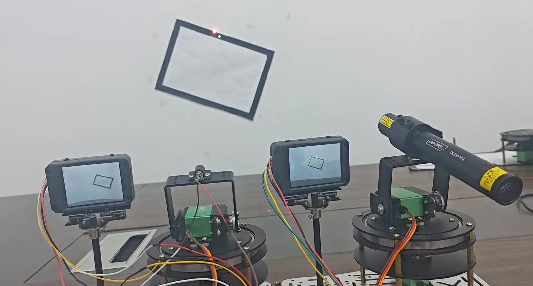
The placement position is shown in the figure. You can choose our aluminum substrate car frame as the baseplate for fixing the K230 and gimbal, or fix them on your own. The distance between K230 and the gimbal is approximately 7cm. The 2D gimbal system is 1m away from the black frame as required by the problem.
4. Experiment Preparation
First, build the 2D gimbal according to the 2D Gimbal Assembly Tutorial.
Hardware Wiring:
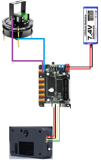
| 2D Gimbal | 24-Channel Servo Driver Board |
|---|---|
| X-Axis Servo | S1 |
| Y-Axis Servo | S2 |
| K230 Vision Module | 24-Channel Motor Driver Board |
|---|---|
| 5V | 5V |
| GND | GND |
| TX | RX3 |
| RX | TX3 |
Note: When plugging in the servo wires, make sure the yellow wire is aligned with the yellow GPIO port of the 24-channel servo driver board, and the brown wire is aligned with the black GPIO port of the 24-channel servo driver board.
5. K230 Key Code Analysis
get_square.py
x# Find inner frameif flag_find_first_rect == False:# The threshold parameter is used to set the detection threshold (the threshold value is related to the pixel size of the rectangle to be detected; setting the threshold within the area range of the rectangle to be detected can reduce external noise)# The x_gradient and y_gradient parameters are used to set the edge gradient threshold (larger x_gradient and y_gradient values mean more accurate recognition but longer processing time; smaller values are faster but more susceptible to interference)# Both are related to ambient brightness# When finding rectangles, adjust threshold, x_gradient, and y_gradient valuesfor rect in img.find_rects(threshold = 80000, x_gradient=10, y_gradient=10):if rect:flag_find_first_rect = True# Get the coordinates of the four corners of the rectanglefirst_rect_corners = rect.corners()area = rect.magnitude() # Rectangle pixel area sizeprint(area)# Find outer frameif flag_find_first_rect == True:if flag_find_second_rect == False:for rect in img.find_rects(threshold = 60000, x_gradient=10, y_gradient=10):if rect:area = rect.magnitude()if area < 90000:flag_find_second_rect = True# Get the coordinates of the four corners of the rectanglesecond_rect_corners = rect.corners()print(area)
This code is to obtain the four corner coordinates of a rectangle. By finding the outer and inner rectangles of the black frame, the center rectangle is determined, and thus the four vertex coordinates of the center rectangle are obtained.
red_light.py
xxxxxxxxxxdef color_blob(img,hano,color):# Find the largest color blob of the specified colorblobs = img.find_blobs([hano],roi=light_roi,merge = True)if blobs:global last_cxglobal last_cyfor blob in blobs:roi = (blob.x()-5,blob.y()-5,blob.w()+10,blob.h()+10)# Get the range of the circumscribed circle of the bright spotif img.find_blobs([color],roi=roi,x_stride=1, y_stride=1,area_threshold=0, pixels_threshold=0,merge=False,margin=1):# Found the specified colorcx = blob[5]cy = blob[6]img.draw_rectangle(blob[0:4],color=(0,0,255)) # Draw rectangleimg.draw_cross(blob[5], blob[6],color=(0,0,255)) # Draw crosslast_cx = cx# Update coordinateslast_cy = cy# Update coordinatesreturn cx, cy, 1return last_cx, last_cy, 0return last_cx, last_cy, 0
This code is to obtain the coordinates of the target color blob. By calling the K230's color blob finding function, blobs within the threshold are found. For this problem, it is the red color blob, so the threshold needs to be defined as red.
Coordinate Segmentation Function
xxxxxxxxxxdef conversion_postion(x,y):if x > 510:x_h = 255x_l = 255x_z = x-255-255elif 510>=x>=255:x_h = 255x_l = x-255x_z = 0else:x_h = xx_l = 0x_z = 0if y > 510:y_h = 255y_l = 255y_z = y-255-255elif 510>=y>=255:y_h = 255y_l = y-255y_z = 0else:y_h = yy_l = 0y_z = 0return x_h,x_l,x_z,y_h,y_l,y_z
Since STM32 can only transmit 8-bit binary numbers, the maximum transmission data is 255. Our K230 uses a resolution of 640x480, so the coordinates need to be segmented. The 640 is split into 3 frames for transmission.
6. Gimbal 1 Key Code Analysis
control.c
xxxxxxxxxxvoid go_to_point(uint16_t now_x, uint16_t now_y, uint16_t targ_x, uint16_t targ_y){uint16_t i;float step_num = 1000;/* 1000 steps*/float step_x, step_y; /* Step values */float going_x = now_x, going_y = now_y; /* Current target values*/step_x = (targ_x - now_x) / step_num;step_y = (targ_y - now_y) / step_num;for(i = 0; i < step_num; i++){kfp_x.source = step_x;kfp_y.source = step_y;kfp_x.out = KalmanFilter(&kfp_x, kfp_x.source);kfp_y.out = KalmanFilter(&kfp_y, kfp_y.source);going_x += kfp_x.out;going_y += kfp_y.out;set_target(going_x, going_y);}}
This code subdivides the coordinates of two points. The idea is to divide the 2 points of a rectangle into many points, then perform PID calculations between these points, making the servo movement more precise. At the same time, it can also control the speed of the servo moving around the black frame.
xxxxxxxxxxuint8_t get_point1_p(){uint8_t lable, load_1, load_2,load_3, ret = 0;if(DataDecode1(&Uart3_RingBuff,&lable, &load_1, &load_2, &load_3) == 0){if(lable == 0x10){rec_step_point[3][0] = (load_1 + load_2 + load_3);} else if(lable == 0x11){rec_step_point[3][1] = (load_1 + load_2 + load_3);} else if(lable == 0x12){rec_step_point[0][0] = (load_1 + load_2 + load_3);} else if(lable == 0x13){rec_step_point[0][1] = (load_1 + load_2 + load_3);} else if(lable == 0x14){rec_step_point[1][0] = (load_1 + load_2 + load_3);} else if(lable == 0x15){rec_step_point[1][1] = (load_1 + load_2 + load_3);} else if(lable == 0x16){rec_step_point[2][0] = (load_1 + load_2 + load_3);} else if(lable == 0x17){rec_step_point[2][1] = (load_1 + load_2 + load_3);mode_flag = 4;}}return ret;}
This code combines the 3 frames of data transmitted from K230. As mentioned earlier, K230's coordinate data is split into 3 frames and transmitted separately. This code combines the data to form the correct rectangle vertex coordinates. Then the x and y coordinates of the rectangle are assigned to the 2D array in sequence. When the last coordinate is acquired, a defined flag is assigned.
xxxxxxxxxxstatic uint8_t step_flag =0;if(step_flag ==0){USART_Cmd(USART3, ENABLE);get_point1_p();// Get coordinates}if(mode_flag == 4&&step_flag==0){USART_Cmd(USART3, DISABLE);// Enable USART3TIM_ITConfig(TIM1,TIM_IT_Update, ENABLE);// Enable timer 1TIM_Cmd(TIM4, ENABLE); // Enable PID timergo_to_point(rec_step_point[0][0], rec_step_point[0][1], rec_step_point[1][0], rec_step_point[1][1]);go_to_point(rec_step_point[1][0], rec_step_point[1][1], rec_step_point[2][0], rec_step_point[2][1]);go_to_point(rec_step_point[2][0], rec_step_point[2][1], rec_step_point[3][0], rec_step_point[3][1]);go_to_point(rec_step_point[3][0], rec_step_point[3][1], rec_step_point[0][0], rec_step_point[0][1]);go_to_point(rec_step_point[0][0], rec_step_point[0][1], rec_step_point[1][0], rec_step_point[1][1]);go_to_point(rec_step_point[1][0], rec_step_point[1][1], rec_step_point[2][0], rec_step_point[2][1]);go_to_point(rec_step_point[2][0], rec_step_point[2][1], rec_step_point[3][0], rec_step_point[3][1]);go_to_point(rec_step_point[3][0], rec_step_point[3][1], rec_step_point[0][0], rec_step_point[0][1]);step_flag+=1;}
Note: Gimbal 1 must first disable USART3 at the location of the serial port definition function. For this code, first define the flag, then open USART3 to run the coordinate acquisition function. After acquisition is complete, another flag is assigned. Under the judgment of two flags, execution continues. Then disable USART3 to prevent serial port data reception from competing with the PID calculation and servo PWM movement processes. Enable the PID calculation timer and PWM movement timer. Then execute the subdivided PID movement function to control the servo to move within the rectangular frame. After movement is complete, add 1 to the flag to stop the servo.
7. Gimbal 2 Key Code Analysis
control.c
xxxxxxxxxxuint8_t get_point2_p() // Coordinate processing function{uint8_t lable, load_1, load_2 ,load_3 ,ret=0;if(DataDecode1(&Uart3_RingBuff,&lable, &load_1, &load_2,&load_3) == 0){if(lable == 0x00){rec_step_p[0][0] = load_1 + load_2 + load_3 ;// ret=1;} else if(lable == 0xff){rec_step_p[0][1] = load_1 + load_2 + load_3 ;// ret=1;}return ret;}}
This code combines the 3 frames of data transmitted from K230. As mentioned earlier, K230's coordinate data is split into 3 frames and transmitted separately. This code combines the data to form the correct coordinates, and assigns the coordinates to the 2D array.
xxxxxxxxxxint a_Err=(int)x_pid.Err, b_Err=(int)y_pid.Err;get_point2_p();if(abs(a_Err) + abs(b_Err) < 800){/* Audio-visual reminder*/BEEP_ON;}else {BEEP_OFF;}set_target(rec_step_p[0][0],rec_step_p[0][1]);
This code uses the coordinates obtained above as the PID target values to control servo movement. At the same time, an audio-visual reminder is given when the sum of X-axis and Y-axis errors is less than the threshold.
8. 2D Gimbal Important Code Analysis
bsp_servo.c
xxxxxxxxxxServTypdef Xserv = {.pwm = 1022,.MAXPWM = 2400,.MINPWM = 500,.MIDPWM = 1097};ServTypdef Yserv = {.pwm = 1022,.MAXPWM = 2100,.MINPWM = 400,.MIDPWM = 933};
This code sets the initial starting position of the servos. Gimbal 1 and Gimbal 2 have different positions, so this needs to be modified to fit the gimbal movement range. Since the zero points of x and y on K230 are in the upper left corner, I set the gimbal's initial power-on position in the upper left corner. Then the gimbal can be adjusted proportionally according to the coordinate changes from K230. If adjusting the gimbal position and fine-tuning the position, these position parameters need to be adjusted.
xxxxxxxxxxvoid servo_ctr(ServTypdef *servo, int PidInput){uint16_t CompSet = servo->MIDPWM + PidInput;if( CompSet > servo->MAXPWM ){CompSet = servo->MAXPWM;} else if ( CompSet < servo->MINPWM ){CompSet = servo->MINPWM;}if(servo->pwm == CompSet){/* Avoid redundant comparison value changes*/return;}if( servo == &Xserv ){GPIO_SetBits(Servo_J1_PORT, Servo_J1_PIN ); // Set servo signal highdelay_us(CompSet); // Delay for the number of microseconds of the pulse valueGPIO_ResetBits(Servo_J1_PORT, Servo_J1_PIN ); // Set servo signal lowdelay_ms(20 - CompSet/1000);}else if( servo == &Yserv ){GPIO_SetBits(Servo_J2_PORT, Servo_J2_PIN ); // Set servo signal highdelay_us(CompSet); // Delay for the number of microseconds of the pulse valueGPIO_ResetBits(Servo_J2_PORT, Servo_J2_PIN ); // Set servo signal lowdelay_ms(20 - CompSet/1000);}}
This code connects the PID output to PWM. It is the link between PID and PWM. It also performs amplitude limiting on the PWM and is the core code for servo movement. It controls servo rotation through delays and PWM changes, connecting servo movement with PWM.
pid.c
xxxxxxxxxxfloat pid_calculate(PID_TypeDef *PID,float CurrentValue){PID->Err = PID->Target - CurrentValue;PID->Integral += PID->Err;if(PID->Integral > 7000){PID->Integral = 7000;}if(PID->Integral < -7000){PID->Integral = -7000;} // Integral limitingPID->PID_out = PID->Kp * PID->Err /* Proportional */+ PID->Ki * PID->Integral /* Integral */+ PID->Kd * (PID->Err - PID->LastErr); /* Derivative */PID->LastErr = PID->Err;return PID->PID_out;}
This code is the configuration of positional PID calculation. It includes integral limiting. Positional PID calculates the current error value (difference between target and actual values), integral value (sum of past errors), and derivative value (rate of error change), then weights and adds these three parts to get the PID output.
bsp_usart.c
xxxxxxxxxxuint8_t DataDecode1(RingBuff_t *ringbuff, uint8_t *data1, uint8_t *data2, uint8_t *data3,uint8_t *data4){static uint8_t uart_dec_count;static uint8_t uart_rec_data[6];uint8_t ret = 1;if(Read_RingBuff(ringbuff, &uart_rec_data[uart_dec_count]) == RINGBUFF_ERR){return 1;}if((uart_dec_count == 0)&&(uart_rec_data[uart_dec_count] != 0x55)) { // Frame header 0x55uart_rec_data[uart_dec_count] = 0;}else if((uart_dec_count == 1)&&(uart_rec_data[uart_dec_count] != 0xaa)){ // Second frame 0xaauart_rec_data[uart_dec_count] = 0;uart_rec_data[uart_dec_count-1] = 0;uart_dec_count = 0;}else if((uart_dec_count == 6)&&(uart_rec_data[uart_dec_count] != 0xfa)){ // Frame tail 0xfauart_rec_data[uart_dec_count] = 0;uart_rec_data[uart_dec_count-1] = 0;uart_rec_data[uart_dec_count-2] = 0;uart_rec_data[uart_dec_count-3] = 0;uart_rec_data[uart_dec_count-4] = 0;uart_rec_data[uart_dec_count-5] = 0;uart_dec_count = 0;}else{if(uart_dec_count == 6)// Successfully received one frame of data{*data1 = uart_rec_data[2];*data2 = uart_rec_data[3];*data3 = uart_rec_data[4];*data4 = uart_rec_data[5];ret = 0;}uart_dec_count++;if(uart_dec_count == 7){uart_dec_count = 0;}}return ret;}
This code is for receiving K230 data. Data is received only when the frame header is 0x55, the second data is 0xaa, and the frame tail is 0xfa. The three data values identify one frame of data. Since the 4 vertex coordinates transmitted from K230 are each split into 3 groups for transmission, the transmitted data is quite large. To ensure the transmitted data is accurate, three data values are used to confirm one frame of data.
9. Effect Demonstration
1. Pencil Frame Drawing Effect Description
The problem requires completing a circle around the perimeter without leaving the line within 30 seconds. Our movement circle time is less than 30 seconds, perfectly meeting the requirements and able to return to the center point.
2. Basic Part Frame Drawing Effect Description
This problem requires moving in a circle within a rectangular frame with a time limit of 30 seconds. As seen from the video, the time perfectly matches the requirement, and the movement is also quite good. Since drawing a regular square is too simple, the demonstration shows drawing an arbitrary frame.
3. Advanced Part Gimbal Tracking Effect Description
This problem requires the red laser pointer to move in a circle while the green laser pointer follows, with the distance between them not exceeding 3cm. There should be an audio reminder when within range. As seen from the video, the red laser pointer's movement is good, and the green laser pointer does not exceed 3cm. There is an audio reminder when tracking is achieved, perfectly meeting the problem requirements.