yahboom
HomeLearn
Solution
Blog
Online Store
About Us
EN/中文
MicroROS V2 Robot Car📖
01.Introduction
  • 0.Unboxing Video
  • 1. Readme Learning Route
  • 2. Must Read Before Use
  • 3. Introduction to MicroROS V2 Control Board
  • 4. Introduction to LiDAR
  • 5. Introduction to ESP32 Camera Module
  • 6. FAQ
  • 7. About Charging
02.Assembly course
  • Assembly Video
03.Preparation
  • 1. Quickly Start
  • 2. Write Firmware
  • 3. Install VM and Start System
  • 4. Configure VM and Connect Robot
  • 5. Connect to MicroROS Agent
04.Quick start control course
  • 1. VM Keyboard Remote Control
  • 2. VM Handle Remote Control
  • 3. USB Handle Control
05.Robot control course
  • 1. Robot Information Release
  • 2. Robot Keyboard Control
  • 3. Robot Handle Control
  • 4. Robot State Estimation
  • 5. Linear Speed Calibration
  • 6. Angular Velocity Calibration
  • 7. Robot URDF Model
06.Lidar course
  • 1. Precautions for LiDAR Mapping and Navigation
  • 2. Lidar Avoid
  • 3. Lidar Following
  • 4. Lidar Guard
  • 5. Lidar Patrol
  • 6. Gmapping Mapping
  • 7. Cartographer Mapping
  • 8. Cartographer Quickly Repositioning Navigation
  • 9. Slam Toolx Mapping
  • 10. Navigation2 Single Point Navigation
  • 11. Navigation2 Multi Point Navigation
  • 12. Ros Robot App Mapping And Navigation
07.Road network planning
  • 1. Introduction to Road Network Planning and Quick Start
  • 2. Build a Pose Map
  • 3. Road Network Annotation
  • 4. Planning and Navigation Between Road Networks
  • 5. Road Network Navigation in Any Pose
  • 6. Path Replanning
08.Vision basic course
OpenCV Image Processing
  • 1. Introduction to OpenCV Source CV
  • 2. Open Source CV Geometric Transformation
  • 3. Open Source CV Image Processing and Drawing Text Line Segments
  • 4. Open Source CV Image Beautification
09.Visual General Course (For Standard&Superior version)
4. Yolov11&26 Visual Recognition
  • 1. YOLO Environment Setup
  • 2. CLI Usage
  • 3. Object Detection
  • 4. Instance Segmentation
  • 5. Pose Estimation
  • 6. Image Classification
  • 7. Oriented Bounding Boxes Object Detection
  • 8. Model Prediction
1. ESP32 Visual Recognition Module Configuration
  • 1. Serial Port Configuration WiFi Instructions
  • 2. Use ESP32 Camera Module in Robot Car
  • 3. Servo PTZ Calibration
2. OpenCV Visual Recognition
  • 1. Human Pose Estimation
  • 2. Object Detection
  • 3. AR Vision
  • 4. QR Code
  • 5. Color Recognition
  • 6. Facial Recognition
  • 7. AprilTag Machine Code Recognition
3. Mediapipe Visual Recognition
  • 1. Hand Detection
  • 2. Pose Detection
  • 3. Holistic Detection
  • 4. Facial Detection
  • 5. Facial Recognition
  • 6. Facial Special Effects
  • 7. 3D Object Recognition
  • 8. Brush
  • 9. Gesture Recognition
  • 10. Palm Target Localization
  • 11. Fingertip Trajectory Recognition
10.Visual Advanced Course (Just for Standard version)
1. Visual Control
  • 1. QR Code Recognition Control Action
  • 2. AprilTag Control Car Action Group
  • 3. Gesture Control Car Action Group
  • 4. Visual Line Tracking
2. Visual Tracking
  • 1. Color Tracking
  • 2. Facial Tracking
  • 3. QR Code Tracking
  • 4. Object Recognition And Tracking
  • 5. Mediapipe Palm Tracking
  • 6. Mediapipe Gesture Tracking
  • 7. Mediapipe Human Pose Tracking
  • 8. KCF Object Tracking
  • 9. AprilTag Machine Code Tracking
3. Visual Following
  • 1. Color Follow
  • 2. Face Follow
  • 3. QR Code Follow
  • 4. Mediapipe Palm Follow
  • 5. Mediapipe Gesture Follow
  • 6. Mediapipe Human Posture Follow
  • 7. AprilTag Machine Code Follow
  • 8. Object Follow
11.Visual Advanced Course (Just for Superior version)
1. Visual Control
  • 1. QR Code Recognition Control Action
  • 2. AprilTag Control Car Action Group
  • 3. Gesture Control Car Action Group
  • 4. Visual Line Tracking
2. Visual Tracking
  • 1. Color Tracking
  • 2. Facial Tracking
  • 3. QR Code Tracking
  • 4. YOLO Object Recognition and Tracking
  • 5. Mediapipe Palm Tracking
  • 6. Mediapipe Gesture Tracking
  • 7. Mediapipe Human Pose Tracking
  • 8. KCF Object Tracking
  • 9. AprilTag Machine Code Tracking
3. Visual Follow
  • 1. Color Follow
  • 2. Face Follow
  • 3. QR Code Follow
  • 4. Mediapipe Palm Follow
  • 5. Mediapipe Gesture Follow
  • 6. Mediapipe Human Pose Follow
  • 7. AprilTag Machine Code Follow
  • 8. Object Follow
12.AI Large Model Basic and Applications Course
1. AI Large Model Preparation
  • 1.AI Large Model Preparation
2. AI Large Model Basic Course
  • 1. AI Large Model Types and Principles
  • 2. RAG Retrieval Augmented and Training Samples
  • 3. Embodied Intelligent System Architecture
  • 4. Embodied Intelligence Core Source Code
3. AI Large Model Development
  • 1. Register Model Service Account
  • 2. Configure API KEY
  • 3. Dify Introduction
  • 4. Dify Basic Features
  • 5. RAG Knowledge Base Deployment
  • 6. AI Application Development Chatbot
  • 7. RAG Knowledge Base and Chatbot
  • 8. AI Agent Workflow
4. AI Large Model (Text Version)
  • 1. Semantic Understanding and Instruction Following
  • 2. Multimodal Visual Understanding
  • 3. Multimodal Visual Understanding + Basic Control
  • 4. Multimodal Visual Understanding + Object Following
  • 5. Multimodal Visual Understanding + Visual Line Following
  • 6. Multimodal Visual Understanding + SLAM Navigation
  • 7. Multimodal Visual Understanding + SLAM Navigation + Visual Line Following
  • 8. Multimodal Visual Understanding + SLAM Navigation + Object Following
  • 9. Intent Inference + Multimodal Visual Understanding + SLAM Navigation
13.Openclaw Basics Course
  • 1. Openclaw Introduction
  • 2. Openclaw Core Concepts
  • 3. Openclaw Api-Key Configuration
  • 4. Openclaw Switching Models
  • 5. Openclaw System Prompt
  • 6. Openclaw Common CLI Command
14. Openclaw Interaction Course
  • 1. Openclaw Webchat Interaction
  • 2. Openclaw Tui Interaction
  • 3. Openclaw Whatsapp Interaction
15.Openclaw Development Course
  • 1. Openclaw Robot Mcp Service Integration
  • 2. Robot CLI Command Tools
  • 3. Robot-Control Plugin Tools
  • 4. Openclaw Skills Development
  • 5. Openclaw Scheduled Tasks
  • 6. Openclaw Multi Agent System
  • 7. Openclaw Proactive Interaction
  • 8. Openclaw Vector Memory
16.Openclaw Embodied Intelligence Course
  • 1. OpenClaw Natural Interaction + Basic Control
  • 2. OpenClaw Natural Interaction + Slam Navigation
  • 3. OpenClaw Natural Interaction + Multimodal Visual Understand
  • 4. OpenClaw Natural Interaction + Multimodal Visual Understand + Slam Navigation + Visual Follow
  • 5. OpenClaw Natural Interaction + Multimodal Visual Understand + Slam Navigation + Visual Track
17.Multi-machine Course
  • 1. Multi Machine Handle Control
  • 2. Multi Machine Keyboard Control
  • 3. Multi Machine Navigation
18.MicroROS-V2 Control Board Development Environment
  • 1. Set Up the ESP32-IDF Development Environment
  • 2. ESP32-IDF Configuration Tool
  • 3. ESP Flash Tool Flashing Firmware
  • 4. Install ESP32 Microros Components
  • 5. Install And Start Microros Agent
19.MicroROS-V2 Control Board ESP32 Basic Course
  • 1. Led Light Up
  • 2. Button Function
  • 3. Drive Buzzer
  • 4. Oled
  • 5. Usb Host Function
  • 6. Serial Communication
  • 7. Battery Voltage Detection
  • 8. Drive Pwm Servo
  • 9. Drive Motors
  • 10. Read Motor Encoder Data
  • 11. Pid Motor Speed Control
  • 12. Robot Kinematics Analysis Theory
  • 13. Read Imu Data
  • 14. Read Lidar Data
  • 15. Flash Data Storage
  • 16. Custom Partition Table
  • 17. Bluetooth Communication
  • 18. Wifi Connection
  • 19. ESP32 Visual Recognition Module
20.MicroROS-V2 Control Board Micro_ros Basic Course
  • 1. Publish Topics
  • 2. Subscribe To Topics
  • 3. Multi Topic Subscription And Publishing
  • 4. Subscribe To Buzzer Topic
  • 5. Subscribe To Pwm Servo Topic
  • 6. Subscribe To Speed Control Topic
  • 7. Publish Odometry Topic
  • 8. Publish Imu Data Topic
  • 9. Publish Lidar Data Topic
21. Linux System Course
  • 1.Introduction to Linux system
  • 2.Ubuntu file system
  • 3.Ubuntu common commands
  • 4.Ubuntu common editors
  • 5.Ubuntu software operation commands
  • 6.Virtual machine installation
  • 7.SSH remote control
  • 8.VNC remote control
  • 9.Transfer files remotely
  • 10.Driver library and communication
  • 11.Static IP and hotspot mode
  • 12.Bind device ID
  • 13.Capacity expansion and resource allocation
  • 14.Update system software sources
  • 15.Set root user password
  • 16.sudo free password
  • 17.Connect to WiFi network
  • 18.View system version
  • 19.Customized service management
  • 20.Back up system image
22.Docker Course
  • 1.Docker overview and docker installation
  • 2.Common commands for docker image containers
  • 3.Docker images deeply understand and publish images
23.ROS Basic Course
  • 1.Introduction to ROS2
  • 2.ROS2 install Humble
  • 3.ROS2 development environment
  • 4.ROS2 workspace
  • 5.ROS2 function package
  • 6.ROS2 node
  • 7.ROS2 topic communication
  • 8.ROS2 service communication
  • 9.ROS2 action communication
  • 10.ROS2 custom interface message
  • 11.ROS2 parameter service case
  • 12.ROS2 meta-function package
  • 13.ROS2 distributed communication
  • 14.ROS2 DDS
  • 15.ROS2 time related API
  • 16.ROS2 common command tools
  • 17.ROS2 rviz2 use
  • 18.ROS2 rqt toolbox
  • 19.ROS2 Launch startup file configuration
  • 20.ROS2 recording and playback tool
  • 21.ROS2 URDF model
  • 22.ROS2 Gazebo simulation platform
  • 23.ROS2 TF2 coordinate transformation
Download
  • Mapping_APP(iOS_Android)
  • Code
  • Software_Tools
  • VM_System_File
  • 3D_Model_File
  • ESP32_Firmware
  • Dify LLM Base
  • Instruction_Manual
  • VMware
Download ZIP

Welcome to MicroROS V2 Robot Car repository

3. Introduction to MicroROS V2 Control Board

MicroROS-V2 Controller Board Introduction

The MicroROS-V2 controller board is a ROS 2 robot controller based on the ESP32-S3-WROOM-1U-N4R2 module. The current version features onboard dual-channel encoder motor drivers, dual-channel PWM servo interfaces, a QMI8658B six-axis IMU, a buzzer, and status LEDs, and provides interfaces for the lidar, WiFi image transmission module, OLED, USB Host gamepad, and serial flashing/debugging.

Onboard Resources
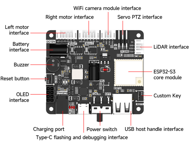
MicroROS-V2 controller board interface layout

Onboard resourceDescription
Battery interfaceConnects a 12V battery to power the controller board and the robot.
Charging interfaceConnects the charging power supply to charge the battery.
Power switchControls the power on/off of the entire board.
Reset buttonResets the ESP32-S3 main controller.
Left/right motor interfacesConnect two DC motors with Hall encoders; the interfaces carry both motor drive and encoder signals.
Servo pan-tilt interfaceProvides S1 and S2, two channels of PWM servo control signals, as well as power.
Lidar interfaceConnects the T-mini Plus lidar, communicating via UART1.
WiFi image transmission module interfaceConnects the companion image transmission/camera module, communicating via UART2.
OLED interfaceConnects the I2C OLED display, using an independent I2C1 bus.
USB Host gamepad interfaceConnects the USB gamepad receiver; the data lines use the ESP32-S3 native USB D-/D+.
Type-C flashing/debugging interfaceUsed for firmware flashing, parameter configuration, and UART0 serial debugging.
Custom buttonKEY1 user button, active low, whose function can be defined by the firmware.
BuzzerOnboard passive buzzer for status and low-voltage alarms.
Status LEDsOnboard blue and green MCU status LEDs.
Six-axis IMUOnboard QMI8658B accelerometer and gyroscope.
ESP32-S3 moduleThe main controller of the board, responsible for motors, sensors, communication, and micro-ROS functionality.

GPIO Pin Assignment

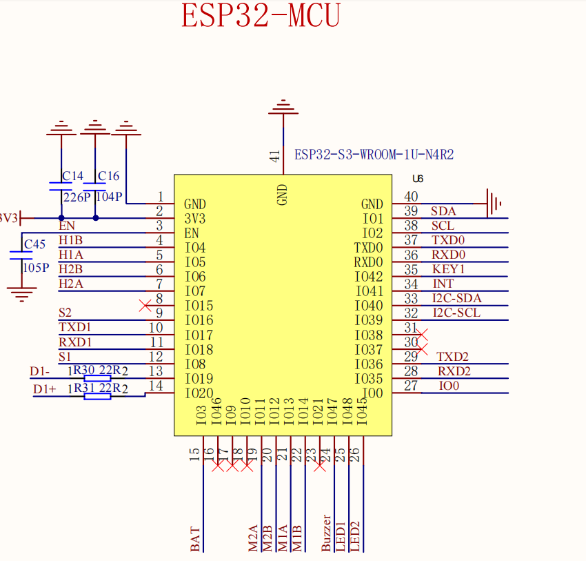
Current ESP32-S3 pin assignment in the schematic

In the following, the directions of TX and RX are defined relative to the ESP32-S3 main controller. For example, UART1 TX means data is sent from the ESP32-S3 to the lidar; when wiring, it should be connected to the lidar's RX.

Motors and Encoders

Interface/FunctionSchematic net nameESP32-S3 GPIOMCU direction
Left motor M1 drive AM1AGPIO13Output
Left motor M1 drive BM1BGPIO14Output
Left motor M1 encoder AH1AGPIO5Input
Left motor M1 encoder BH1BGPIO4Input
Right motor M2 drive AM2AGPIO11Output
Right motor M2 drive BM2BGPIO12Output
Right motor M2 encoder AH2AGPIO7Input
Right motor M2 encoder BH2BGPIO6Input

Servos, Display, and IMU

Interface/FunctionSchematic net nameESP32-S3 GPIODescription
Servo S1S1GPIO8PWM output; used by the firmware for the horizontal (pan) direction
Servo S2S2GPIO16PWM output; used by the firmware for the pitch direction
OLED dataSDAGPIO1I2C1 SDA
OLED clockSCLGPIO2I2C1 SCL
IMU dataI2C-SDAGPIO40I2C0 SDA
IMU clockI2C-SCLGPIO39I2C0 SCL
IMU interruptINTGPIO41IMU interrupt input

OLED and IMU use two independent I2C buses and must not be wired to the same set of SDA/SCL pins.

Serial Port and USB

Interface/FunctionSchematic net nameESP32-S3 GPIOConnection
Lidar UART1 TXTXD1GPIO17ESP32-S3 TX -> lidar RX
Lidar UART1 RXRXD1GPIO18ESP32-S3 RX <- lidar TX
WiFi image transmission UART2 TXTXD2GPIO36ESP32-S3 TX -> image transmission module RX
WiFi image transmission UART2 RXRXD2GPIO35ESP32-S3 RX <- image transmission module TX
Flashing/debugging UART0 TXTXD0GPIO43ESP32-S3 TX -> USB-to-serial RX
Flashing/debugging UART0 RXRXD0GPIO44ESP32-S3 RX <- USB-to-serial TX
USB Host D-D1-GPIO19Native USB data line D-
USB Host D+D1+GPIO20Native USB data line D+

Buttons, Detection, and Status Output

Interface/FunctionSchematic net nameESP32-S3 GPIODescription
Battery voltage detectionBATGPIO3ADC input
Custom buttonKEY1GPIO42Digital input, active low
Download/BOOT controlIO0GPIO0Boot configuration pin
BuzzerBuzzerGPIO47PWM output, drives the passive buzzer
Blue status LEDLED1GPIO48Digital output, lights up on high level
Green status LEDLED2GPIO45Digital output, lights up on high level

Wiring Notes

  • The logic level of the ESP32-S3 GPIOs is 3.3V, and the GPIOs are not 5V tolerant; do not connect the 5V power pin of an interface directly to a GPIO signal pin.
  • UART must be cross-connected: connect this board's TX to the peripheral's RX, and this board's RX to the peripheral's TX, and make sure the two ends share a common ground.
  • The numbering of motors M1/M2 follows the schematic net names; the left/right orientation depends on the current firmware configuration. When adjusting the mechanical mounting orientation, do not swap the encoder A/B definitions.
  • GPIO0 is the boot configuration pin; during startup or reset, do not hold it externally low for a long time, otherwise the board may enter download mode.
  • Before connecting or disconnecting motors, servos, the lidar, and image transmission modules, it is recommended to turn off the controller board power first.
Must Read Before Use
Introduction to LiDAR

COMPANY

  • About us
  • Team Style
  • Blog

LEARNING & EXPLORATION

  • Tutorials
  • Edge AI hardware
  • Educational robots
  • Embedded intelligent hardware

WHERE TO BUY

  • Yahboom Online Store
  • Amazon
  • Alibaba
  • AliExpress
  • Mercado

TECHNOLOGY SUPPORT

  • Email: support@yahboom.com

BE A DISTRIBUTOR

  • Email: sales@yahboom.com
QR Code

Copyright © 2017-2026 Yahboom. All Rights Reserved.

EN/中文