Welcome to MicroROS V2 Robot Car repository
5. Subscribe To Pwm Servo Topic
Subscribing to the PWM Servo Topic
1. Experiment Objective
In this experiment, you will learn how to control the two PWM servos on the MicroROS-V2 control board through micro-ROS topics. Through this example, you will master multiple-subscriber management, the use of FreeRTOS Task Notifications, and the design pattern of using critical sections to protect shared data. This example subscribes to Int32 messages on the topics /servo_s1 and /servo_s2 respectively. The lower 8 bits of the message are parsed as an angle value of type int8_t, controlling the corresponding servo to rotate to the target angle.
2. Experiment Principle
1. Keyword Explanation
| Keyword | Description |
|---|---|
| micro-ROS Agent | A proxy program running on the ROS2 host side, responsible for bridging communication between the ESP32 firmware and the ROS2 system, connecting with the microcontroller via the UDP protocol |
| subscriber | The subscriber, the message-receiving end in ROS2 communication, subscribes to messages on a specified topic and triggers the callback function to process data when a new message arrives |
| rclc | A ROS2 client library for microcontrollers, providing lightweight node, publisher, subscriber and other APIs, adapted to resource-constrained embedded devices |
| QoS (Reliable) | The "reliable transmission" mode in the quality-of-service policy, which guarantees message delivery and ordering, suitable for control-type messages (such as servo commands) to ensure state consistency |
| FreeRTOS Task Notification | A lightweight inter-task communication mechanism provided by FreeRTOS, which directly sends a notification to a specified task. It is more efficient than a queue and suitable for simple event-trigger scenarios |
| critical section | A critical section, which protects shared data by disabling interrupts or using a mutex lock, preventing data races caused by concurrent access from multiple tasks |
2. Technical Architecture
This experiment builds a control chain from the ROS2 host to the two PWM servos on the ESP32:
Hardware layer: The MicroROS-V2 control board (ESP32), with servo S1 connected to GPIO8 and servo S2 connected to GPIO16, driven by the MCPWM peripheral
Transport layer: Uses the UDP protocol, communicating with the ROS2 host through the micro-ROS Agent
Node configuration: Node name
servo_subscriber, subscribing to topics/servo_s1and/servo_s2Message type:
std_msgs/msg/Int32, with the lower 8 bits parsed as an angle value of typeint8_tQoS mode: Reliable (default), ensuring servo control commands are reliably delivered
Data flow: ROS2 host publishes a message → Agent → UDP → micro-ROS stack → executor → subscription callback (updates the shared angle values + task notification) → servo worker thread → reads the target angle in a critical section →
Servo_Set_Angle()→ MCPWM hardware controlDesign pattern: Three-task separation (micro-ROS communication task + servo execution task), critical sections protect shared data, and task notifications serve as wake-up signals
3. Core Topic Quick Reference
Firmware Downlink (Control Commands)
| Topic | Message Type | QoS | Field | Range | Direction |
|---|---|---|---|---|---|
/servo_s1 | std_msgs/msg/Int32 | Reliable | data lower 8 bits parsed as int8_t | S1: -90°~90° | Input, controls the horizontal servo |
/servo_s2 | std_msgs/msg/Int32 | Reliable | data lower 8 bits parsed as int8_t | S2: -90°~20° | Input, controls the vertical servo |
Usage Example:
# Servo S1 rotates to 90°ros2 topic pub /servo_s1 std_msgs/msg/Int32 "data: 90"# Servo S2 rotates to -45° (camera facing straight ahead)ros2 topic pub /servo_s2 std_msgs/msg/Int32 "data: -45"4. Middleware Configuration
micro-ROS uses a static memory model (RCUTILS_AVOID_DYNAMIC_ALLOCATION=ON), all entity memory is pre-allocated at compile time, and runtime dynamic creation is not supported.
Configuration file:
~/esp/extra_components/micro_ros_espidf_component/colcon.meta
| RMW_UXRCE_TRANSPORT | udp | UDP transport (Wi-Fi communication) |
| RMW_UXRCE_MAX_PUBLISHERS | 6 | Maximum number of publishers |
| RMW_UXRCE_MAX_SUBSCRIPTIONS | 6 | Maximum number of subscribers |
| RMW_UXRCE_MAX_NODES | 1 | Maximum number of nodes |
| RMW_UXRCE_MAX_SERVICES | 0 | Services not supported |
| RMW_UXRCE_MAX_CLIENTS | 0 | Clients not supported |
| RMW_UXRCE_MAX_HISTORY | 1 | History depth = 1, no message queuing |
| UCLIENT_UDP_TRANSPORT_MTU | 4096 | Maximum UDP packet size 4 KB |
| UCLIENT_MIN_HEARTBEAT_TIME_INTERVAL | 1 | Agent heartbeat interval 1 ms |
Key Constraints:
MAX_HISTORY=1means there is no message buffer queue, so uplink topics (firmware → host) uniformly use best_effort QoSMAX_SERVICES=0, MAX_CLIENTS=0means only topic communication is supported, not Service/ClientAfter modifying
colcon.meta, the micro-ROS library must be recompiled for the changes to take effect: runidf.py clean-microrosin the project directory to clean and rebuild the micro-ROS library, thenidf.py buildto compile the firmware
3. Experiment Steps
1. Hardware Preparation
| Hardware | Requirement |
|---|---|
| MicroROS-V2 control board | ✅ Required |
| USB Type-C cable | ✅ Required |
| Wi-Fi network (2.4 GHz) | ✅ Required |
| PWM servo ×2 | ✅ Required (connected to GPIO8 and GPIO16) |
2. Prerequisites
The ESP32-IDF development environment has been set up
The MicroROS-V2 control board is connected to the computer via USB
Configure the Wi-Fi SSID, password, Agent IP and port via
idf.py menuconfig(themicro_rosmenu item)xxxxxxxxxxcd ~/esp/microROS_samples/servo_subscribersource ~/esp/esp-idf/export.shidf.py menuconfig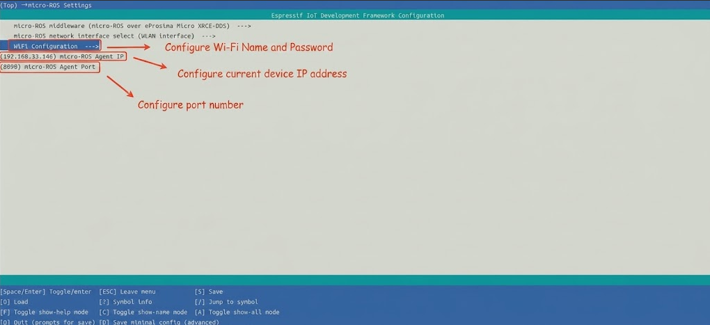
Select example-app setting to set the domain ID to be consistent with the virtual machine
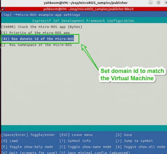
After configuration, press "s" to save and press "q" to exit the configuration interface.
Connect servo S1 to GPIO8 and servo S2 to GPIO16
3. Start micro_ros_agent (Terminal 1)
Start the micro-ROS Agent on the ROS2 host:
xxxxxxxxxxcd ~/uros_wssource install/local_setup.bashros2 run micro_ros_agent micro_ros_agent udp4 --port 8090 -v44. Build and Flash (Terminal 2)
x
cd ~/esp/microROS_samples/servo_subscribersource ~/esp/esp-idf/export.shidf.py build flash monitor
5. How to Stop
Press
Ctrl+]in Terminal 2 to exit the serial monitor (stop firmware execution)Press
Ctrl+Cin Terminal 1 to stop micro_ros_agent
4. Experiment Result
After the build and flash succeed, publish servo control commands on the ROS2 host:
xxxxxxxxxx# Servo S1 rotates to 90°ros2 topic pub /servo_s1 std_msgs/msg/Int32 "data: 90"
# Servo S1 rotates to -90°ros2 topic pub /servo_s1 std_msgs/msg/Int32 "data: -90"
# Servo S2 rotates to 0° (camera facing upward)ros2 topic pub /servo_s2 std_msgs/msg/Int32 "data: 0"
# Servo S2 rotates to -45° (camera facing straight ahead, default angle)ros2 topic pub /servo_s2 std_msgs/msg/Int32 "data: -45"
The control board serial port will output:
xxxxxxxxxxI (xxx) MAIN: Agent reachable: 192.168.x.x:8888I (xxx) MAIN: micro-ROS servo subscriber init doneI (xxx) MAIN: Servo S1: 90I (xxx) MAIN: Servo S2: -45
Data encoding quick reference table:
| Target angle | Int32 data (hexadecimal) | Int32 data (decimal) |
|---|---|---|
| 90° | 0x0000005A | 90 |
| 45° | 0x0000002D | 45 |
| 0° | 0x00000000 | 0 |
| -45° | 0xFFFFFFD3 | -45 |
| -90° | 0xFFFFFFA6 | -90 |
Tip: The
datafield ofstd_msgs/msg/Int32is the signedint32type. On the ROS2 command line, you can directly use the signed decimal value (such asdata: -45), without manually converting to an unsigned representation.
5. Program Analysis
Source code paths:
Firmware source code:
~/esp/microROS_samples/servo_subscriber/main/main.cServo driver:
~/esp/microROS_samples/servo_subscriber/components/servo/servo.h,servo.c
1. Main Program Logic
main/main.c adopts a three-task separation design:
In
app_main():Calls
Servo_Init()to initialize the MCPWM peripherals for the two servosCreates the
servo_worker_tasktaskInitializes the Wi-Fi network
Creates the
micro_ros_tasktask
In
micro_ros_task:Creates the node
servo_subscriberSubscribes to topics
/servo_s1and/servo_s2in Reliable mode (servo control requires reliable transmission)The two subscription callbacks update the target angle of the corresponding servo and wake up the execution task via task notification
In
servo_worker_task:Waits for the task notification
Reads the target angles under the protection of a critical section
Calls
Servo_Set_Angle()to drive the servos
2. Key Components
components/servo/servo.h — Servo driver interface:
Parameter definition file:
~/esp/microROS_samples/servo_subscriber/components/servo/servo.h
| Pin/Parameter | Value | Description |
|---|---|---|
SERVO_GPIO_S1 | 8 | PWM signal line of servo S1 |
SERVO_GPIO_S2 | 16 | PWM signal line of servo S2 |
SERVO_TIMEBASE_RESOLUTION_HZ | 1000000 | 1 MHz, 1 us resolution |
SERVO_TIMEBASE_PERIOD | 20000 | 20000 ticks = 20 ms period |
SERVO_MIN_PULSEWIDTH_US | 500 | Minimum pulse width 500 us (corresponding to -90°) |
SERVO_MAX_PULSEWIDTH_US | 2500 | Maximum pulse width 2500 us (corresponding to 90°) |
Servo angle limits:
| Servo | Default angle | Minimum angle | Maximum angle | Description |
|---|---|---|---|---|
| S1 | 0° | -90° | 90° | Horizontal servo, fully adjustable range |
| S2 | -45° | -90° | 20° | Vertical servo, -45° means the camera faces straight ahead |
components/servo/servo.c — Core servo driver functions:
| Function | Description |
|---|---|
Servo_Init() | Initializes the MCPWM peripherals of servos S1 and S2 and sets the default angles |
Servo_Set_Angle(servo_id_t servo, int8_t angle) | Sets the target angle of the specified servo (automatically clamped) |
Angle encoding/decoding rules:
The angle command uses the lower 8 bits of the Int32 message, parsed as int8_t:
xxxxxxxxxxstatic inline int8_t servo_decode_angle_compat(int32_t raw_value){ return (int8_t)(raw_value & 0xFF);}Examples:
data: 90(hexadecimal0x0000005A) → lower 8 bits 0x5A = 90 → 90°data: -90(hexadecimal0xFFFFFFA6) → lower 8 bits 0xA6 = -90 → -90°
Task notification and critical section design:
Source file:
~/esp/microROS_samples/servo_subscriber/main/main.c
xxxxxxxxxx/* Subscription callback: only updates the target value, does not directly drive the servo */static void servo_s1_callback(const void *msgin){ const std_msgs__msg__Int32 *msg = (const std_msgs__msg__Int32 *)msgin; const int8_t angle = servo_decode_angle_compat(msg->data);
taskENTER_CRITICAL(&s_servo_lock); s_servo_target_s1 = angle; taskEXIT_CRITICAL(&s_servo_lock);
(void)xTaskNotify(s_servo_worker_handle, SERVO_NOTIFY_S1, eSetBits);}
/* Servo execution task: all actual Servo_Set_Angle calls are executed here uniformly */static void servo_worker_task(void *arg){ while (1) { uint32_t notify_value = 0; xTaskNotifyWait(0, UINT32_MAX, ¬ify_value, portMAX_DELAY);
taskENTER_CRITICAL(&s_servo_lock); int8_t angle_s1 = s_servo_target_s1; int8_t angle_s2 = s_servo_target_s2; taskEXIT_CRITICAL(&s_servo_lock);
if ((notify_value & SERVO_NOTIFY_S1) != 0U) { Servo_Set_Angle(SERVO_ID_S1, angle_s1); } if ((notify_value & SERVO_NOTIFY_S2) != 0U) { Servo_Set_Angle(SERVO_ID_S2, angle_s2); } }}Topic configuration:
Parameter definition file:
~/esp/microROS_samples/servo_subscriber/main/main.c
| Configuration Item | Value | Description |
|---|---|---|
| Node name | servo_subscriber | ROS2 node name |
| Topic names | servo_s1, servo_s2 | Control the two servos respectively |
| Message type | std_msgs/msg/Int32 | Lower 8 bits parsed as angle of type int8_t |
| QoS mode | Reliable (default) | Control-type messages must be reliably transmitted; packet loss would cause servo state inconsistency |
| Executor handle count | 2 | 2 subscribers |
6. Common Problems
| Problem | Cause | Solution |
|---|---|---|
| The servo does not rotate | The servo is not connected correctly or the power supply is insufficient | Check whether the servo connections are correct (S1→GPIO8, S2→GPIO16) and ensure sufficient servo power |
| Abnormal servo angle | Angle value encoding error or out of limits | Confirm the angle is within the allowed range of the servo (S1: -90~90°, S2: -90~20°); out-of-range values are automatically clamped |
| Servo jitter after publishing a message | QoS packet loss causes state inconsistency | The servo subscription uses Reliable mode to ensure reliable transmission |
| Servo response delay | Scheduling delay in task notification | This is normal behavior, about 1~2 FreeRTOS ticks of delay |
Safety tip: The servo angles are automatically limited to the defined ranges (see
SERVO_Sx_MIN_ANGLEandSERVO_Sx_MAX_ANGLEinservo.h). Out-of-range values are clamped to protect the servos from damage.