Welcome to MicroROS V2 Robot Car repository
3. Servo PTZ Calibration
Servo PTZ Calibration
1. Experiment Objective
Calibrate the initial angle of the PTZ pan-tilt servos, compensate for installation errors through firmware offset parameters, and ensure the camera orientation is accurate.
2. Experiment Principle
2.1 Keyword Explanation
| Keyword | Description |
|---|---|
| PTZ | Pan-Tilt-Zoom, a pan-tilt control system. This platform uses two PWM servos, S1 (horizontal) and S2 (pitch) |
| Servo offset | An angular offset applied by the firmware to the PWM control signal, used to compensate for mechanical angle deviations caused during servo installation |
| PWM servo | A servo whose angle is controlled through pulse width modulation, with a typical control period of 20ms; a 0.5~2.5ms pulse width corresponds to 0°~180° |
| NVS persistence | The offset parameters are written into the ESP32 non-volatile storage, which is not lost on power-off; the firmware automatically loads them each time the board is powered on |
2.2 Technical Architecture
The offset parameters are written into the control board firmware by the configuration software through the serial port. The firmware automatically loads the offset values from NVS at every power-on and adds them before the PWM output:
PC(config_robot.py)│ USB serial port → 0x08 command frame (servo_id + offset value)▼ESP32-S3 firmware config window│ Write to NVS (servo_1_offset / servo_2_offset)│ Automatically loaded at power-on▼PWM output = target angle + offset (hardware offset compensation)│▼S1 horizontal servo / S2 pitch servo
After the offset calibration is complete, the upper-layer ROS2 visual control node does not need to care about hardware installation errors; it only needs to send control commands directly using logical angles.
3. Experiment Steps
3.1 Hardware Preparation
| Hardware | Requirement |
|---|---|
| PTZ version | ✅ Supported |
| No-PTZ version | ❌ No pan-tilt hardware, skip this section |
| Required peripherals | PTZ pan-tilt servos, Type-C data cable |
3.2 Prerequisites
- The control board has been connected to the virtual machine via a Type-C data cable
- The control board is powered on and the servos have been installed on the pan-tilt bracket
- Confirm the serial port device exists:
ls -l /dev/microros_boardproduces output
3.3 Configure Offset Parameters
Note: For other parameters, see the Serial Port Configuration WiFi Instructions in Section 1
- Double-click the RobotManager application icon on the virtual machine desktop
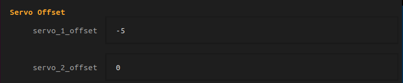
- In the motor control board, find the servo offset
| Parameter Name | Default Value | Description | Adjustment Suggestion |
|---|---|---|---|
servo_1_offset | 0 | S1 horizontal pan-tilt offset, in degrees | Increase it appropriately when the camera is oriented too far to the left; decrease it when too far to the right. Positive value = correct to the right, negative value = correct to the left |
servo_2_offset | 0 | S2 pitch pan-tilt offset, in degrees | Increase it appropriately when the camera is oriented too low; decrease it when too high. Positive value = correct upward, negative value = correct downward |
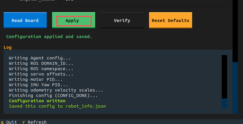
- Click "Apply Configuration" to write the above parameter configurations to the MicroRos control board
Adjustment suggestions:
- Adjust in small increments of 1°~3° each time, then run the configuration script and observe the actual direction the servo points
- If the physical assembly direction is opposite to the above phenomenon, follow the actual movement direction and adjust in the opposite direction
3.4 Verify the Calibration Effect
Re-power the control board and observe whether the servo points straight ahead after the power-on initialization. If there is any deviation, repeat Step 3.3 for fine adjustment.
4. Experiment Phenomena
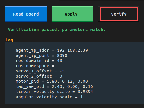
Click "Verify" to confirm that the calibration parameters are consistent; the control board parameter configuration is complete