Welcome to MicroROS V2 Robot Car repository
1. Serial Port Configuration WiFi Instructions
Serial Port WiFi Configuration Guide
1. Experiment Purpose
Connect to the control board over the serial port and use the configuration script to configure both the control board WiFi and the ESP32 camera module WiFi in one go.
2. Experiment Principle
1. Key Term Explanation
| Keyword | Description |
|---|---|
| Serial port configuration | Communicates with the ESP32-S3 control board over the USB virtual serial port (UART) and sends binary configuration frames |
| Configuration frame protocol | A custom binary protocol: frame header (0xFF) + device ID (0xF8) + payload length + command code + payload + checksum |
| NVS | Non-Volatile Storage, the non-volatile storage of the ESP32 where parameters such as the WiFi password are persisted |
| config window | A configuration window of about 2 seconds after the firmware powers up; configuration commands are accepted only during this window |
| CAMERA_CONFIG_NOW | A dedicated protocol command relayed through the control board serial port that sends the WiFi information down to the ESP32 camera module |
2. Technical Architecture
The configuration flow is relayed through the control board, so there is no need to connect the camera module directly:
PC (config_robot.py)│ USB serial port (/dev/ttyUSB0 or /dev/microros_board)▼ESP32-S3 control board (firmware config window)│ UART2▼ESP32 camera module (receives the WiFi config and connects)
Data flow: config_robot.py sends binary command frames over the serial port → the control board firmware parses them and writes to NVS / forwards them to the camera module → the camera module connects to WiFi and returns its IP → the script reads back the IP address with the CAMERA_QUERY_IP_NOW command.
3. Experiment Steps
1. Hardware Preparation
| Hardware | Requirement |
|---|---|
| PTZ version | ✅ Supported |
| No-PTZ version | ✅ Supported |
| Required peripherals | ESP32 vision module, Type-C data cable |
2. Prerequisites
- The control board is connected to the virtual machine via a Type-C data cable
- The camera module is installed on the car and connected to the control board with a ribbon cable
- Confirm that the serial device exists:
ls -l /dev/microros_boardhas output
3. Edit the Configuration Parameters
Editable parameters:
| Parameter | Default | Description | Adjustment Suggestion |
|---|---|---|---|
main_wifi_ssid | SSID | The Wi-Fi name the robot main controller connects to | Change it to an available 2.4G Wi-Fi; the ESP32-S3 does not support 5G Wi-Fi |
main_wifi_passwd | PASSWORD | The Wi-Fi password the robot main controller connects to | Must correspond to the Wi-Fi name above |
agent_ip_addr | [192, 168, 33, 146] | The IP address of the computer/virtual machine running the micro-ROS Agent | Change it to the real IP of the virtual machine or host on the same LAN; keep the format as 4 numbers |
agent_ip_port | 8090 | The UDP port of the micro-ROS Agent | No need to change by default; if a different port was specified when starting the Agent, keep it consistent here |
ros_domain_id | 77 | ROS_DOMAIN_ID | Must match the ROS_DOMAIN_ID in the virtual machine terminal |
ros_namespace | "" | ROS namespace | Keep it as an empty string for a single robot; fill it in only when multiple robots need to separate topics, e.g. "robot1" |
servo_1_offset | 0 | S1 pan offset, in degrees | Fine-tune when the camera is not pointing straight ahead; positive corrects to the right, negative corrects to the left |
servo_2_offset | 0 | S2 tilt offset, in degrees | Fine-tune when the camera pitch is off; positive corrects upward, negative corrects downward |
motor_pid | (1.8, 0.12, 0.0) | Chassis motor speed loop PID | Normal users should not modify; change it only when motion control behaves abnormally and tuning is explicitly needed |
imu_yaw_pid | (2.4, 0.0, 0.16) | Straight-line heading-hold PID | Normal users should not modify; change it only when the straight-line heading-hold performance needs optimization |
Servo offset adjustment notes:
servo_1_offsetadjusts the pan servo S1. When the camera points too far left, increase the value appropriately; when it points too far right, decrease the value appropriately.servo_2_offsetadjusts the tilt servo S2. When the camera points too low, increase the value appropriately; when it points too high, decrease the value appropriately.- It is recommended to make small adjustments of 1° ~ 3° each time, then re-run the configuration script and observe the effect.
- If the actual assembly direction is opposite to the behavior described above, adjust the offset values in the opposite direction based on the actual movement direction.
4. Run the Configuration
4.1 Configure the Control Board Parameters
Double-click the RobotManager application icon on the virtual machine desktop
Click the Control Board panel and fill in the WiFi name and password (make sure the board is on the same subnet as the virtual machine)
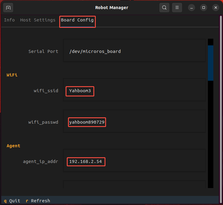
- Fill in
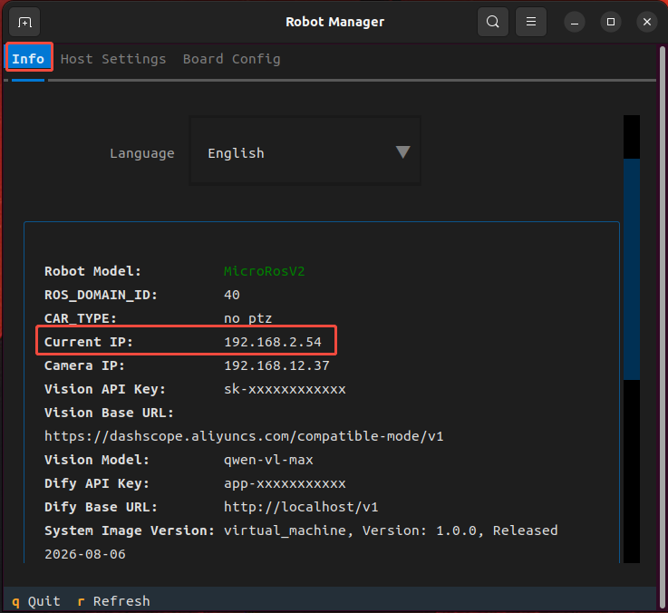
agent_ip_addrwith the virtual machine IP address; you can view the virtual machine IP address in the Info panel
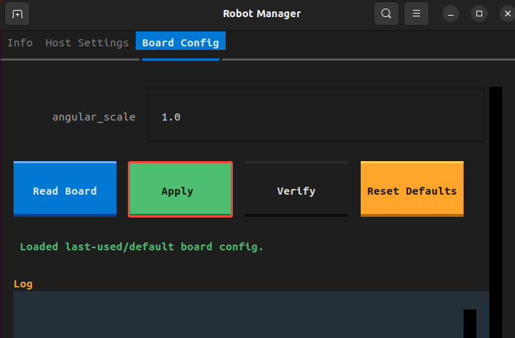
- Click Apply Configuration to write the above parameters to the MicroRos control board
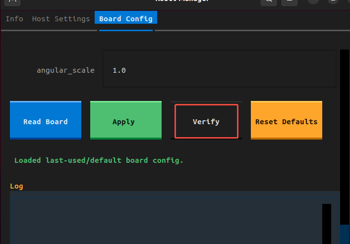
- Click Verify to confirm the parameters match, and the control board parameter configuration is complete
- Press the button on the right side of the control board to switch the OLED screen display and view the information
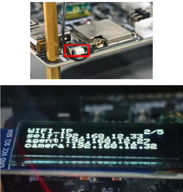
self: the vehicle's own IP address, make sure it is on the same subnet as the virtual machine
agent: the virtual machine IP address written in the previous step
camera: the IP address of the image transmission camera
4.2 Configure the Vehicle Type and Camera IP in the Virtual Machine
- In the host settings, open the CAR_TYPE dropdown list and select the corresponding vehicle model
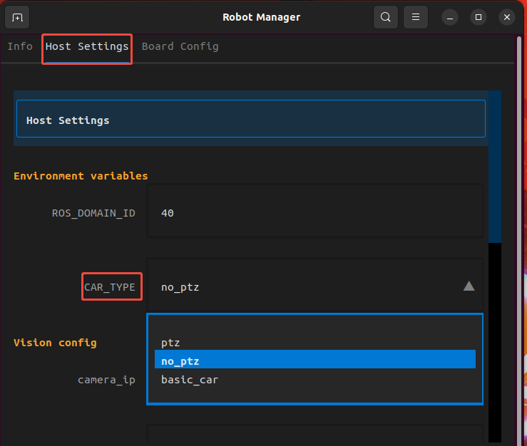
- The vehicle model names are as follows:
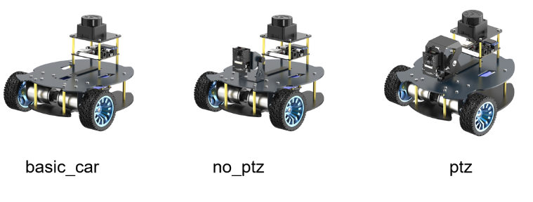
- For the camera IP configuration, fill in the camera IP address shown on the vehicle's OLED screen
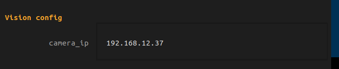
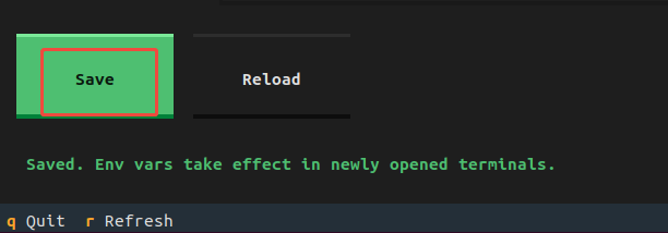
- Click Save Configuration, then press
qor simply close the window to exit RobotManager