Welcome to Jetson Orin NANO Developer Kit repository
21.ROS2 URDF model
21. ROS 2 URDF Model
1. Introduction to URDF
The modeling method in ROS is called URDF, whose full name is Unified Robot Description Format. It can clearly describe not only the robot's own model but also the robot's external environment. URDF model files use the XML format.
SolidWorks model to URDF plugin: sw_urdf_exporter - ROS Wiki
2. Robot Components
When modeling and describing a robot, you first need to be familiar with the robot's components and parameters. For example, a robot is generally composed of four major parts: hardware structure, drive system, sensor system, and control system. Common robots on the market, whether mobile robots or robotic arms, can be decomposed according to these four components.
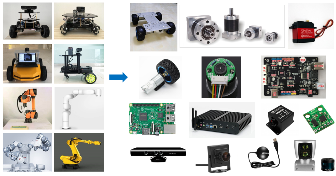
The hardware structure refers to the devices that can actually be seen, such as the chassis, housing, and motors;
The drive system refers to the devices that enable these devices to operate normally, such as the motor driver and the power management system;
The sensor system includes the encoder on the motor, the onboard IMU, the installed camera, radar, and so on, so that the robot can perceive its own state and the external environment;
The control system is the main carrier of our development process, generally a computing platform such as a Raspberry Pi or a computer, together with its operating system and application software.
The robot modeling process actually follows a similar approach: describe every part of the robot clearly with a modeling language, and then combine them.
3. URDF Syntax
3.1. Link Description
The tag is used to describe the appearance and physical properties of a rigid body part of the robot. The appearance includes size, color, and shape, while the physical properties include mass, inertia matrix, collision parameters, and so on.
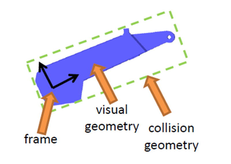
Taking this robotic arm link as an example, its link description is as follows:
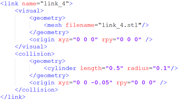
The name in the link tag indicates the name of the link. You can customize it, and this name will be used when a joint connects links later.
The
indicates the geometric shape. Inside it, references a blue appearance designed in advance in 3D software, that is, this STL file, which looks consistent with the real robot. indicates the offset of the coordinate frame relative to the initial position, namely the translation along the x, y, and z directions and the roll, pitch, and raw rotations. If no offset is required, all of them are 0.
The second part,
The
part focuses on describing how the robot looks, that is, the visual effect; The
part describes the robot's state during motion, for example, how contact between the robot and the outside world counts as a collision.
In this robot model, the blue part is described by
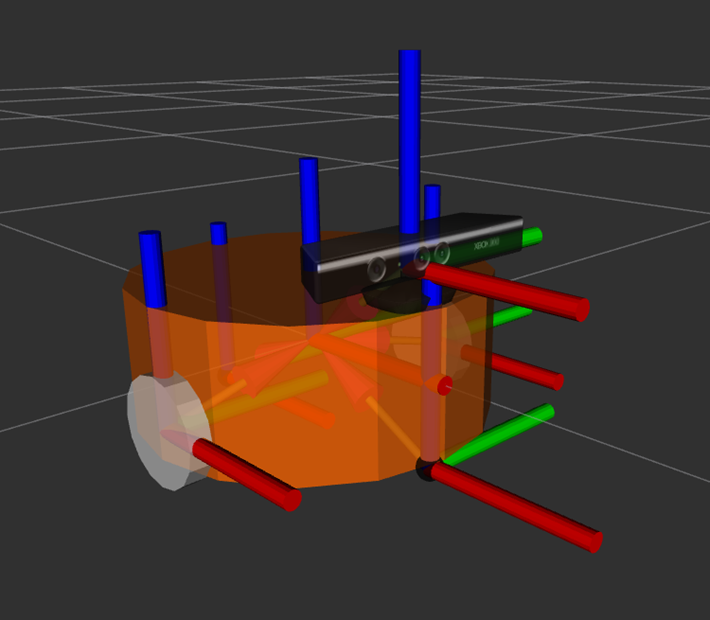
For a mobile robot, link can also be used to describe parts of the car such as the body and the wheels.
3.2. Joint Description
Rigid bodies in a robot model can only produce relative motion after they are connected through joints.
Joints in URDF have six motion types.
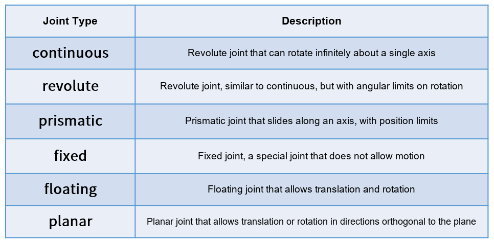
continuous, which describes rotational motion and can rotate infinitely around one axis, such as the wheels of the car.
revolute, which is also a revolute joint. The difference from the continuous type is that it cannot rotate infinitely but has an angle limit, such as the two links of a robotic arm.
prismatic, which is a sliding joint and can translate along one axis, also with a position limit. A linear motor generally uses this motion mode.
fixed, a fixed joint, which is the only joint that does not allow motion. However, it is used quite frequently. For example, the relative position of a camera link installed on the robot does not change, and the connection mode used at this time is Fixed.
Floating is a floating joint, and the sixth type, planar, is a planar joint. These two are used relatively rarely.
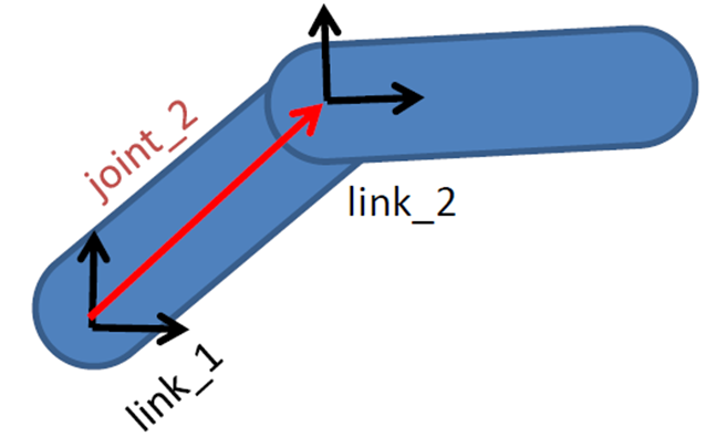
In a URDF model, every link is described with such a piece of XML content, for example, the name of the joint and the motion type.
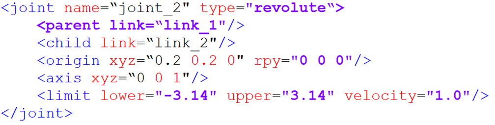
parent tag: describes the parent link;
child tag: describes the child link, and the child link moves relative to the parent link;
origin: indicates the relationship between the coordinate frames of the two links, that is, the red vector in the figure. It can be understood as how the two links should be mounted together;
axis indicates the unit vector of the joint motion axis. For example, if z equals 1, it means the rotational motion is around the positive direction of the z-axis;
limit indicates some limits on the motion, such as the minimum position, the maximum position, and the maximum velocity.
4. Complete Robot Model
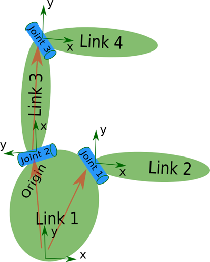
Finally, all the link and joint tags complete the description and combination of every part of the robot. All of them are placed in one robot tag, forming the complete robot model.
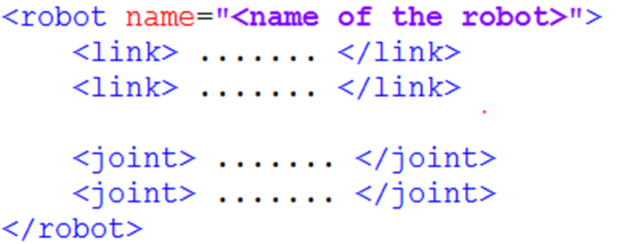
Therefore, when looking at a URDF model, do not rush to read the details of each piece of code. First find the links and joints to see which parts the robot consists of, and after understanding the whole picture, look at the details.
4.1. Creating a Robot Model
Taking the muto model as an example, copy the yahboomcar_description package in this lesson's folder to the src directory of the workspace:
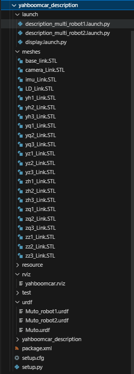
urdf: stores the URDF or xacro files of the robot model
meshes: stores the model rendering files referenced in the URDF
launch: stores the related launch files
rviz: stores the rviz configuration file
Then build the package.
colcon build --packages-select yahboomcar_description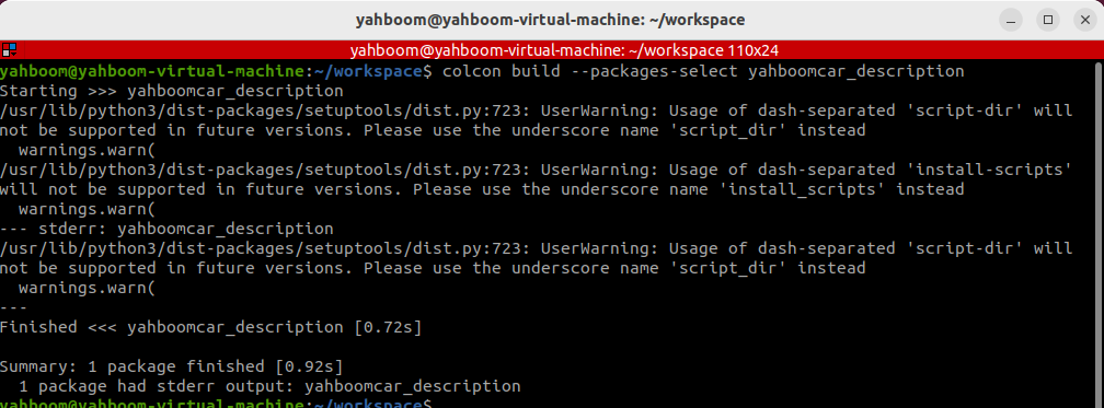
4.2. Model Visualization Effect
Refresh the environment variables, and then run the launch command.
xxxxxxxxxxros2 launch yahboomcar_description display.launch.py
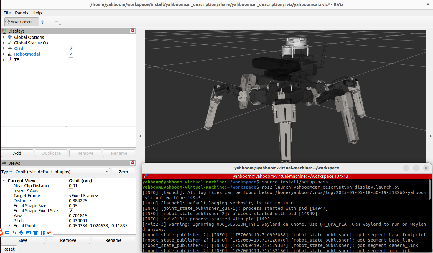
After that, rviz starts automatically and displays the robot model: